This manual provides instructions on installing the VME Sync board upgrade into the CHALLENGE™ L (deskside) and XL (rackmount) family of computer systems. This information is intended for Silicon Graphics system support engineers (SSEs) and other field-certified personnel only.
 | Note: The VME Sync board is not currently supported on the Onyx L and XL platforms. |
The VME Sync board provides synchronous data communications front-end processing for the VMEbus and handles both SNA (system network architecture) and X.25 communications protocol.
The VME Sync board also provides four interface ports that can be configured as RS-232, V.35, or X.21.
 | Caution: Do not mix different interface modules on the same board. For example, you cannot install both RS-232 and V.35 modules on the same VME Sync board; the board must contain the same type of interface. You can, however, install different VME Sync board types in the same system. |
Optional daughter boards (also called line interface modules—LIMs) are used to configure a port for either V.35 or X.21 operation. A set of PROMs provide the standard RS-232 capability. The CHALLENGE system can support up to four VME Sync boards depending on the availability of VME slots.
| Note: This upgrade requires IRIX version 5.2 or later for proper operation. |
This manual is organized as follows:
Chapter 1, "General Information," introduces the VME Sync board, describes the controls and indicators, and provides a brief hardware summary for the VME Sync board.
Chapter 2, "Installation," provides kit content information, describes the jumpers and DIP switches, and describes how to install the upgrade into CHALLENGE systems.
Chapter 3, "Configuring the VME Sync Board" describes how to configure the board.
Appendix A, "VME Sync Board Error Messages," describes the VME Sync error messages.
Appendix B, "Specifications" provides specifications for the VME Sync board.
This section provides important guidelines to follow during installation.
 | Warning: Installation of these upgrades requires specific training and technical knowledge. These instructions have been provided for use only by Silicon Graphics' system support engineers (SSEs) or other Silicon Graphics-trained personnel. This equipment utilizes electrical power internally that is hazardous if the equipment is improperly disassembled. |
| Caution: This equipment is extremely sensitive and susceptible to damage caused by electrostatic discharge (ESD). ESD is an electrical discharge (spark) caused by the buildup of electrostatic potential on clothing and other materials. You must use proper ESD preventive measures and observe these precautions: |
Connect a ground strap to your wrist when connecting/disconnecting peripherals.
Be sure that you and all the electrical equipment that you handle during this installation are at ground potential to avoid damage from ESD.
Keep the boards or drives in the antistatic bags provided. Remove a board or drive from its antistatic bag only when you are properly grounded to the chassis ground with a ground strap.
The figure and tables in this section describe the controls, indicators, connectors, and jumpers on the VME Sync board. Figure 1-1summarizes these connector features.
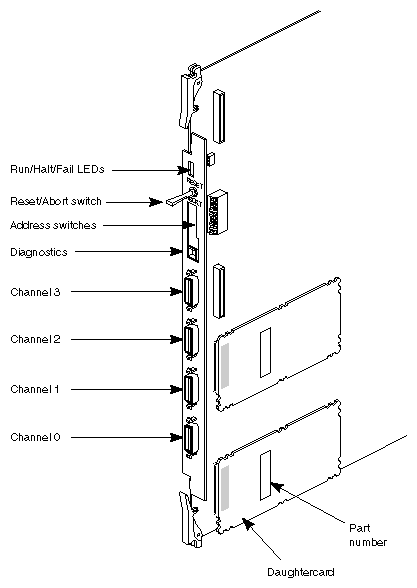
Table 1-1summarizes the board controllers and indicators.
Table 1-1. VME Sync Board Controls and Indicators
Panel Designation | Function |
|---|---|
Run/Halt/Fail | This three-LED indicator shows the current state of the board during operation. "Run" is the normal operating mode. "Halt" indicates that a double-bus error condition has occurred. "Fail" occurs when the SYSFAIL line goes high, indicating a catastrophic condition. See Table 1-2 through Table 1-9 for additional information. |
Reset/"normal"/Abort switch | This is a 3-position momentary toggle switch. The switch is fixed in the middle position (which does not affect normal board operation). The Reset position resets the VME Sync board. The Abort position generates an NMI (nonmaskable interrupt) which is used for diagnostic testing.[a] |
Status LEDs (0 through 7) | These eight LEDs illuminate during power-up, then turn off one by one, as the board cycles through the power-up tests. Afterwards, only one LED (0) should remain blinking. |
Diag port | This diagnostic port is not intended for use in the field. The port is for the manufacturer's use only. |
Port 0 to 3 | These four mini-DB, 26-pin ports provide connection to the I/O panel. |
[a] The Abort position is for the manufacturer's use only. | |
The Run, Halt, Fail States three-LED indicator shows the current state of the board during operation:
"Run" is the normal operating mode.
"Halt" indicates that a double-bus error condition has occurred.
"Fail" occurs when the SYSFAIL line goes high, indicating a catastrophic condition.
Table 1-2 through Table 1-9 summarize these states. Figure 1-2 through Figure 1-9 provide the LED pattern information.
Table 1-2. Run, Halt, Fail States - Normal
LED Pattern | Condition |
|---|---|
Normal | Normal operating state. |
See Figure 1-2. |
|

Table 1-3. Run, Halt, Fail States - Watchdog timeout
LED Pattern | Condition |
|---|---|
Watchdog timeout | Watchdog timeout. See Section 2.2, "Verifying the Jumper and DIP Switch Settings," for more information on this timeout. |
See Figure 1-3. |
|

Table 1-4. Run, Halt, Fail States - CPU halt
LED Pattern | Condition |
|---|---|
CPU halt | CPU halt by the 68020 processor on the VME Sync board that is caused possibly by a double-bus fault. |
See Figure 1-3 |
|

Table 1-5. Run, Halt, Fail States - CPU/SYSFAIL halt
LED Pattern | Condition |
|---|---|
CPU/SYSFAIL halt | Indicates both a CPU halt and a system fail halt. |
See Figure 1-3 |
|

Table 1-6. Run, Halt, Fail States - No power
LED Pattern | Condition |
|---|---|
No power | Power-off state (that is, no power is coming to the board). |
See Figure 1-6 |
|

Table 1-7. Run, Halt, Fail States - Board reset
LED Pattern | Condition |
|---|---|
Board reset | Indicates that the board is in a power-up or reset state. |
See Figure 1-3 |
|

Table 1-8. Run, Halt, Fail States - VMEbus access
LED Pattern | Condition |
|---|---|
VMEbus access | Indicates local accessing of the VMEbus. |
See Figure 1-8 |
|

Table 1-9. Run, Halt, Fail States - Board failure
LED Pattern | Condition |
|---|---|
Board failure | Probable board failure. |
See Figure 1-9 |
|

The VME Synchronous Communications (VME Sync) adapter is a third-party board produced by SBE, Inc. A Motorola 68020 is the main processor on the board. The VME Sync also comes with 1 MB of on-board, parity-protected dynamic RAM.
An AMD 85C30 dual-channel serial communications controller provides serial-to-parallel conversion and control. The SBE SPMCC programmable serial port microcontroller (with DMA) interfaces the 85C30 to the 68020 microprocessor and controls the receiving and transmission of data blocks.
The VMEbus interface is provided by a pair of ASICs that are produced by SBE, called the VBIC and VSAM.
The board also provides four multiprotocol full-duplex serial ports operating in RS-232, X.21, or V.35 mode. All ports are configured for DTE operation. An RS-232 port can transmit up to 64 Kbits per second. An X.21 or V.35 port can transmit up to 1.544 Mbits per second.