This chapter describes how to install the Triple Keyboard Option (TKO). The installation procedure is divided into the following steps:
Preparing the chassis
Attaching the IO4 daughtercards and installing the IO4 boards
Attaching new 24W7 cables in cardcage 3
Installing the TKO panels on the cardcage 2 I/O door
Attaching ribbon cables
Attaching stereo sync cables
Cabling the keyboards
Cabling serial ports
Restarting the system and installing the software
Configuring the TKO
Testing the new installation
Other Silicon Graphics manuals contain instructions for exchanging circuit boards. Make sure you have the appropriate one(s):
CHALLENGE™/Onyx Rackmount Installation Instructions (108-7042-xxx)
CHALLENGE and Onyx Retrofit Instructions (domestic version: 802-0107-002; international version: 802-0106-002)
Challenge/Onyx Rackmount Third Cardcage (CC3) Upgrade Instructions (release note, 802-0105-xxx)
Make sure you have other pertinent release notes and Field Information Bulletins as well.
You need a flat-blade screwdriver and a Phillips screwdriver to install TKO.
Before you install the option, follow these steps:
 | Caution: Board components are extremely sensitive to electrostatic discharge. Use proper antistatic procedures while handling the board. |
Make sure all users are off the target system. Shut down the system and open the chassis to expose the slots.
The three IO4 boards for TKO must all sit in cardcage 2; the second IO4 must go into slot 9 and the optional third IO4 must go into slot 7 for the kernel to recognize it.
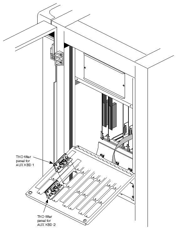
A processor board, existing options, or both might have to be moved to accommodate all the IO4 boards. For example, one of the processor boards or a memory board can be moved to cardcage 1 if it has an appropriate vacant slot.The TKO's two panels are installed on the cardcage 2 I/O door; plan where to install them. To avoid interfering with removal of VME boards, they should not be installed in the bottom row of slots. Figure 2-1 diagrams this placement.
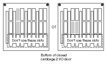
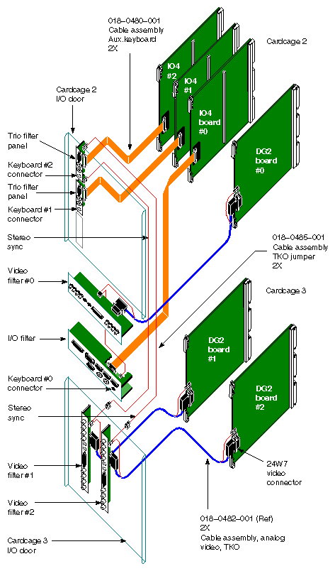
Figure 2-2 diagrams a complete example installation.
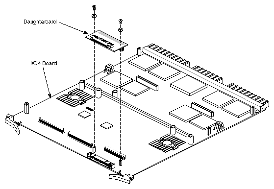
The TKO includes two daughtercards, one for the second IO4 board in slot 9 in the system, and one for the additional IO4 (to be the third IO4 in the system). To attach the daughtercards, follow these steps:
Attach one of the daughtercards to the small edge connector on the optional third IO4. The connector (the only one that fits the daughtercard) is located on the side farthest from the LEDs. See Figure 2-3.
Remove the second IO4 board from slot 9 in cardcage 2.
Attach the daughtercard to the second IO4 board as shown in Figure 2-3.
Reinsert the IO4 you removed from the chassis into slot 9 of cardcage 2.
Insert the optional third IO4 into slot 7 of cardcage 2. If necessary, move a processor board or memory board to cardcage 1.
On the cardcage 3 I/O door, install the I/O panel for the optional third IO4. If necessary, install the I/O panel for the second IO4. Cable each panel to its IO4.
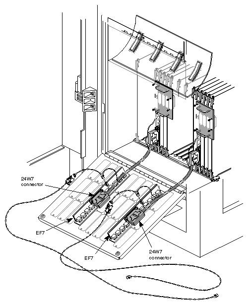
The two 24W7 cables with extra long stereo pigtail cables replace the existing 24W7 cables for graphics heads 1 and 2 in cardcage 3. The pigtail cables are thin black and white cables, twisted together; they might be encased in protective plastic sheaths.
 | Note: The existing 24W7 cable in cardcage 2 for graphics head 0 is left as is. |
To install the new 24W7 cables for graphics heads 1 and 2, follow these steps:
In cardcage 3, detach the 24W7 from the DG2 boards in graphics heads 1 and 2, including the swap ready cable and the stereo sync cable.
Attach the modified 24W7s to the DG2 boards in graphics heads 1 and 2.
Attach the small twisted-pair swap ready cables to the appropriate connectors on the DG2s for graphics heads 1 and 2.
Slide each stereo sync connector onto the connector on the EF7 (video filter panel).
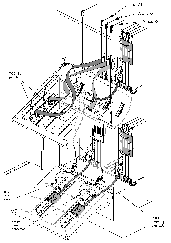
Attach a pigtail cable (p/n 018-0485-001) to the stereo sync connector on each EF7 cable. See Figure 2-4.
TKO I/O for the additional keyboards is handled on two filter panels installed on the cardcage 2 I/O door.
The filterboard/panel assemblies themselves are identical, but must be differentiated by means of labels, because each filterboard is cabled to a specific IO4 and a specific graphics pipe, as outlined in Table 2-1. If necessary, refer to the layout diagrammed in Figure 2-2.
Table 2-1. Filter Panel Cabling
Filter Panel Label | To Be Cabled to IO4 (Ribbon Cable) | To Be Cabled to | Suggested Placement |
|---|---|---|---|
AUX KBD 1 | Second | 1 (cardcage 3) | L eft or bottom
|
AUX KBD 2 | Optional third | 2 (cardcage 3) | Right or top |
Follow these steps:
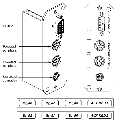
Attach a label to each filter panel. Figure 2-5 shows the position on the panel where the label should be applied.
On the cardcage 2 I/O door, remove the slot covers for the slots you have selected for the TKO I/O panels. Retain the screws.
Note: Do not use the bottom row of slots. Panels installed there make it difficult to remove VME boards. Position the filter panel labeled AUX KBD 1 on the bottom or left slot (as viewed with the I/O door closed); use the retained screws to screw it in.
Position the filter panel labeled AUX KBD 2 on the top or the right slot (as viewed with the I/O door closed) whose cover you have removed; screw it in. Figure 2-6 shows the filter panels installed.
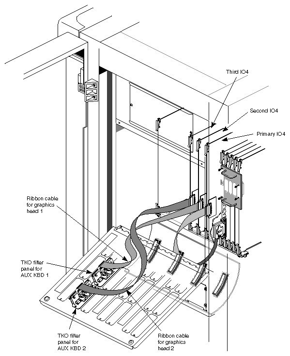
Ribbon cables connect the daughtercards on the second IO4 and the optional third IO4 to the TKO filterboards. (Of course, the primary IO4 board's ribbon cable is already attached to the I/O panel at the bottom of cardcage 2.) Follow these steps:
Attach one end of a ribbon cable to the connector on the daughtercard on the second IO4. The connectors on the ribbon cables are keyed. Attach the other end to the bottom or leftmost filter panel on the cardcage 2 I/O door, as viewed with the I/O door closed. This should be the filter panel labeled AUX KBD 1.
Attach one end of the second ribbon cable to the connector on the daughtercard on the new third IO4. Attach the other end to the top or rightmost filter panel on the cardcage 2 I/O door (as viewed with the I/O door closed). This should be the filter panel labeled AUX KBD 2. Figure 2-7 shows the ribbon cables installed.
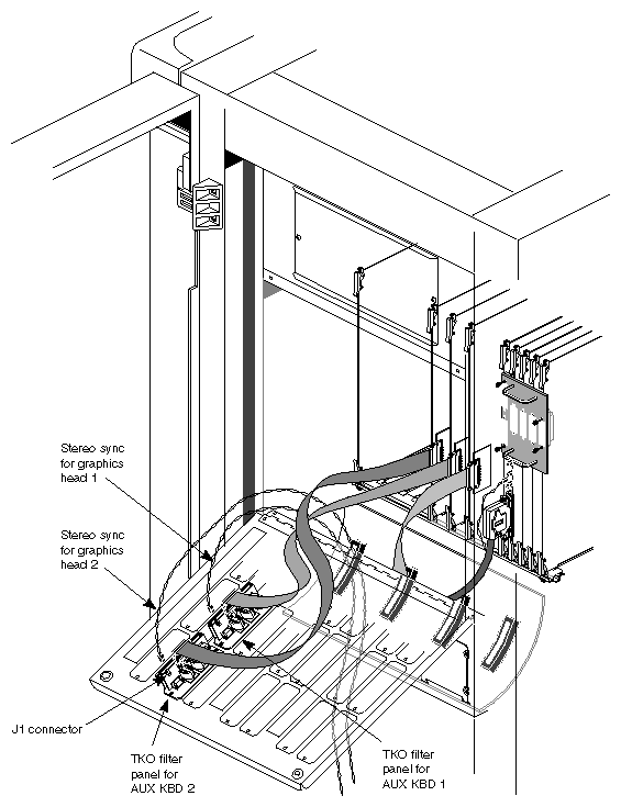
The long black-and-white twisted stereo sync pigtail cables that you plugged into the 24W7s must be plugged into the J1 connectors of the corresponding filterboards (on the I/O door of cardcage 2). Follow these steps:
Thread the pigtail cable from the 24W7 for graphics head 1 up through an appropriate slot in the cardcage 2 floor.
Slide the connector from the stereo sync cable onto the J1 connector on the AUX KBD 1 filterboard. This should be the left or bottom filter panel, as viewed with the I/O door closed.
Thread the pigtail from the other 24W7 up through the slot; slide its connector onto the J1 connector on the AUX KBD 2 filterboard. See Figure 2-8.
If necessary, tie down the pigtails to keep them out of the way. Use a tie wrap to tie the pigtail cables to a 24W7 cable in cardcage 3; use a sticky-back tie wrap to attach the pigtail cables loosely to the cardcage 2 wall. Figure 2-9 shows all internal cables, boards, and daughtercards installed.
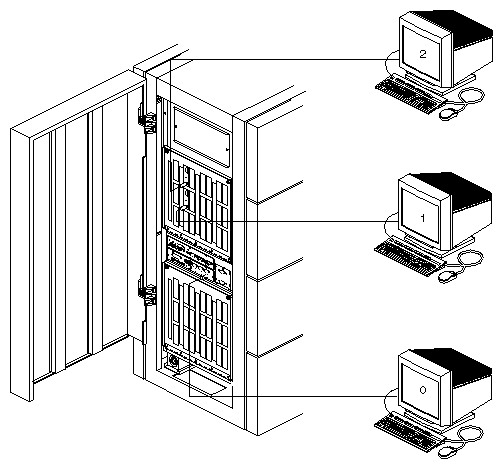
Determine where the customer wants the additional monitors, keyboards, and mice, and place them there. Make sure there is agreement on the numbering of the monitor and keyboard combinations.
The standard (suggested) configuration is summarized in Table 2-2.
Table 2-2. Cabling Keyboards for TKO
Keyboard | Cabling |
|---|---|
0 (Original) | Leave cabled as is to the original I/O panel, which is internally cabled to graphics head 0 |
1 | Keyboard connector on the bottom or leftmost filter panel (AUX KBD 1) on the cardcage 2 I/O door, which is internally cabled to second IO4 and graphics head 1 |
2 | Keyboard connector on the top or rightmost filter panel (AUX KBD 2) on the cardcage 2 I/O door, which is internally cabled to optional third IO4 and graphics head 2 |
Attach keyboard and monitor extension cables to the appropriate connectors on the I/O panels. Figure 2-10 diagrams attachment of the keyboard and monitor cables.
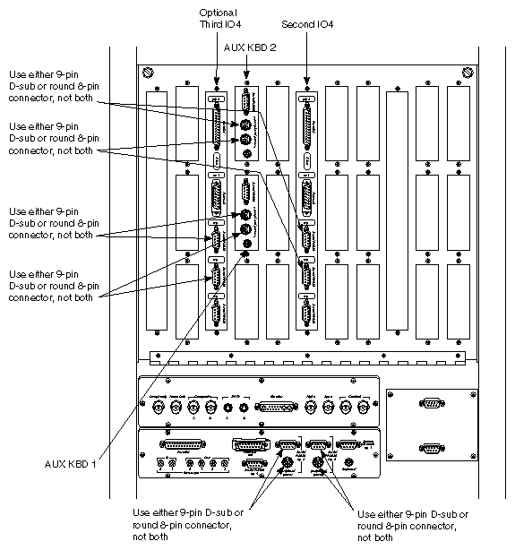
The main I/O panel on the Onyx rackmount provides two types of ports for RS-232 peripherals—a 9-pin sub-D and a round 8-pin DIN connector. On the main I/O panel, these connectors are arranged one above the other; a bracket on the silkscreen links the two types of ports to indicate that only one should be used and not both.
However, the TKO filterboard panels have only the round 8-pin DIN connectors for powered peripherals (TTY 46 and TTY 47 on the TKO filter panel with AUX KBD 1, and TTY 50 and TTY 51 on the TKO filter panel with AUX KBD 2). The corresponding 9-pin sub-D connectors are on the standard I/O panels for the second and third IO4s. Although for the second and third IO4s the two types of serial ports are on separate panels, still only one or the other type of port can be used at one time, not both, just as in the case of the main I/O panel.
Table 2-3 summarizes serial port correspondences.
Table 2-3. Serial Port Correspondences
Round 8-pin DIN Connector Label | Corresponds to Sub-D Label |
|---|---|
AUX KBD 1 panel: TTY_46 | I/O panel for second IO4: TTY_46 |
AUX KBD 1 panel: TTY_47 | I/O panel for second IO4: TTY_47 |
AUX KBD 2 panel: TTY_50 | I/O panel for optional third IO4: TTY_50 |
AUX KBD 2 panel: TTY_51 | I/O panel for optional thrid IO4: TTY_51 |
| Note: Use the serial port listed in one column or the other, not both. For example, if you use the round 8-pin DIN connector for TTY 46 on the AUX KBD 1 panel, do not also use the 9-pin sub-D for TTY 46 on the I/O panel. |
Figure 2-11 shows serial port usage.
The version of IRIX 5.2 for TKO is on an inst-able CD-ROM that is ordered separately (marketing code SC4-TKO-5.2). TKO-specific differences are in eoe1, desktop_eoe, and x_eoe.
Load the TKO software from the CD-ROM. Installing this software changes some of the IRIX system files, so backup is recommended.
The TKO software includes an example version of the xdm Xservers configuration file in /var/X11/xdm, called Xservers.3key. The standard three-keyboard operation described in this chapter is mapped as follows:
main keyboard mapped to graphics pipe 0
auxiliary keyboard 1 mapped to graphics pipe 1
auxiliary keyboard 2 mapped to graphics pipe 2
To set up IRIX for this operation, follow these steps:
Copy /var/X11/xdm/Xservers.3key over /var/X11/xdm/Xservers.
To execute the new xdm configuration file, rlogin, or log in through a serial port, and type as root:
/usr/gfx/stopgfx
/etc/killall xdm
/usr/gfx/startgfx
To set up the software for a different configuration, edit /var/X11/xdm/Xservers, as explained in the next section.
The TKO software includes an example version of the xdm Xservers configuration file called Xservers.3key; this file is located in /var/X11/xdm. The example file shows how to modify the X servers file for three-keyboard operation.
The two files differ in the line(s) specifying X server configuration. The standard /var/X11/xdm/Xservers file has one line defining the X server configuration:
:0 secure /usr/bin/X11/X [default options] |
The /var/X11/xdm/Xservers.3key file has three lines defining the X server configuration:
:0 secure /usr/bin/X11/X :0 -boards 0 -devdir /dev/input [default options] :1 secure /usr/bin/X11/X :1 -boards 1 -devdir /dev/input1 [default options] :2 secure /usr/bin/X11/X :2 -boards 2 -devdir /dev/input2 [default options] |
These lines start X servers for all three keyboards. The -boards n parameter specifies the graphics pipe(s) to be used by the Xserver.
The configuration in Xservers.3key matches the standard hardware configuration described in this chapter: the main keyboard is mapped to graphics pipe 0, auxiliary keyboard 1 is mapped to graphics pipe 1, and auxiliary keyboard 2 is mapped to graphics pipe 2.
If the customer wants a different configuration, edit /var/X11/Xdm/Xservers. For example, the following lines map the main keyboard to graphics head 0 and auxiliary keyboard 1 to graphics heads 1 and 2:
:0 secure /usr/bin/X11/X :0 -boards 0 -devdir /dev/input [default options] :1 secure /usr/bin/X11/X :1 -boards 1,2 -devdir /dev/input1 [default options] |
| Note: For more information on -boards and -devdir, see the Xsgi(1) reference page from IRIX 5.2 for TKO. For more information on graphics pipe numbers, run /usr/gfx/gfxinfo. |