This chapter describes how to install up to six IO4 boards into a CHALLENGE XL or POWER CHALLENGE XL (rackmount) system and describes the special cable routing considerations that are required for additional SCSI mezzanine cards (S1 or SCIP).
 | Note: Before you install the additional IO4 boards, be sure to check the patch server at patches.csd or the patch Web page, http://www-cse.csd.sgi.com/Projects/patches/, to determine if software patches are required. |
The fifth and sixth IO4 boards can be installed only in slots 7 and 5 in cardcage 2. The fifth IO4 board must reside in slot 7, and the sixth IO4 board must go into slot 5 (see Figure 2-1). The additional IO4 boards support only ATM or SCSI (S1 or SCIP) mezzanine cards, as described in the following sections.
This section briefly describes how to install an ATM board. For complete installation and configuration instructions, see the IRIS ATM Installation Instructions (p/n 108-0113-xxx).
The IRIS ATM board has a set of jumpers called the Unit Jumper Set, illustrated in the IRIS ATM Installation Instructions. These jumpers must be configured to give the board a unique unit identification number (for example, ATM unit 0, ATM unit 1, and so on.). Follow the instructions in IRIS ATM Installation Instructions.
| Note: If two or more installed boards have the same unit number, the first board that the operating system locates is initialized and brought into operation, but the duplicates are not. When the system encounters each duplicate board, it prints an error message, then skips the board without initializing it. The command /sbin/hinv does not list uninitialized boards, and they do not have device files in the /dev directory. |
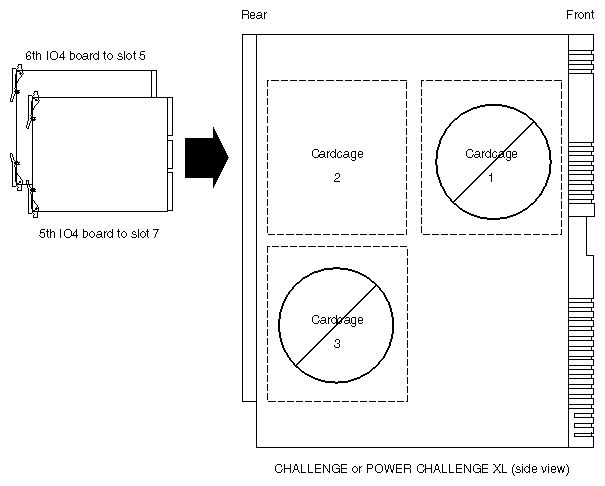
 | Caution: Do not install the IO4 boards in cardcage 1 or 3. |
Follow the steps in this section to prepare the rackmount system for installation.
| Caution: This equipment is extremely sensitive and susceptible to damage by electrostatic discharge (ESD), a spark caused by the buildup of electrostatic potential on clothing and other material. You must use proper ESD preventive measures as explained in the "Safety" section of the CHALLENGE/Onyx XL Rackmount Installation Instructions. |
Use the command below to verify that the IRIX™ operating system is the correct version for this IRIS ATM release. The IRIS ATM Release Notes indicate the correct version. Do not proceed until the correct version of IRIX is installed.
% versions eoe1
I  eoe1  date  Execution Only Environment 1, version
Verify that the filesystem is backed up.
Shut down the system by turning the key on the System Controller panel (located at the front) to OFF.
Wait a minute for the system to shut down, then switch the power switch on the lower front corner of the chassis to OFF.
 | Warning: Failure to turn off the circuit breaker may result in electrical shock. Failure to wait for the system to shut down may cause irreparable damage to system components or data. |
Open the back door and pull down the I/O panel for cardcage 2 to expose the IO4 boards and VMEBus slots, as illustrated in Figure 2-2.
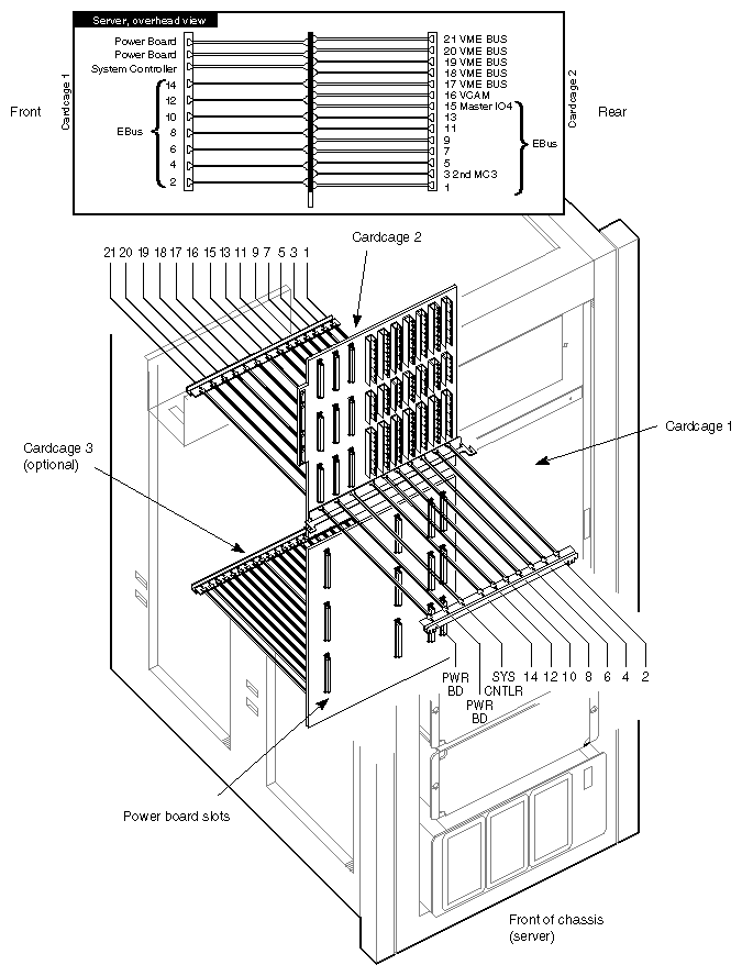
| Caution: This equipment is extremely sensitive and susceptible to damage by electrostatic discharge (ESD), a spark caused by the buildup of electrostatic potential on clothing and other material. You must use proper ESD preventive measures as explained in the "Safety" section of the CHALLENGE/Onyx Rackmount Installation Instructions. |
Follow the steps below to install the IRIS ATM board.
Remove the IO4 board from the system.
Place the board on a flat antistatic surface so that the component side faces up and the SCSI connectors face toward you, as illustrated in Figure 2-3.
Locate the selected mezzanine slot (upper or lower) and remove the four screws from the standoffs, as illustrated in Figure 2-3. If the screws are missing, this is not a problem.
Position the IRIS ATM board onto the selected slot so that the connector on the bottom of the board matches the receptacle on the IO4 board and the standoffs match the ATM board's holes. Figure 2-3 illustrates the correct positioning for the upper and lower slots.
Replace the standoff screws. These screws have a "float" feature, and do not tighten. If necessary, use the screws that are shipped with the IRIS ATM package.
Reinstall the IO4 board into the chassis. Push the board firmly into the backplane. If the board has a VCAM board, the VCAM board must also seat into the backplane.
Create an adapter identification for the ATM mezzanine board. The identification has the format F-XX-5 for the lower slot and F-XX-6 for the upper slot, where XX is the slot number where the IO4 board resides. For example, a mezzanine board in the upper position (IO adapter 6) on the main IO4 board located in slot 15 is labeled F-15-6.
From the sheets of labels, remove a small-sized label with the identification created in the previous step. Attach the label to the outside of the ATM I/O panel plate that is attached to the internal cable assembly (illustrated in Figure 2-4).
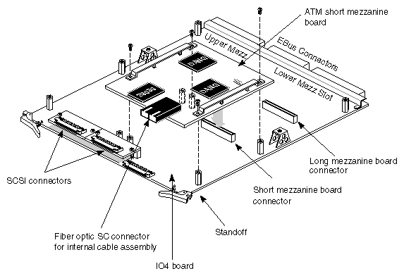
Follow the steps below to attach the internal ATM cables to the ATM board and the panel plate to the cardcage's I/O panel.
| Caution: Do not touch the fiber optic material exposed at the ends of the cable. Do not leave the cable ends uncapped. Performance of the fiber optic cable can seriously degrade due to grease or dust. |
Locate the internal cable assembly that consists of two fiber optic lines terminated inside an SC connector at one end and a MIC receptable attached to the ATM I/O panel plate at the other end, as illustrated in Figure 2-4.
Note: For installations with multiple IRIS ATM boards, replace the single-port panel plate on the cable assembly with the two-port panel plate that is shipped with the product.
Remove one blank panel plate from the system's I/O panel and install the ATM panel plate.
Remove the protective caps from the SC connector.
Slide the SC connector into the ATM board's fiber optic receptacle. To ensure proper orientation, the SC plug has guide ridges that must slide into slots in the receptacle.
Close the I/O door and the chassis door.
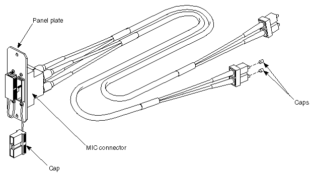
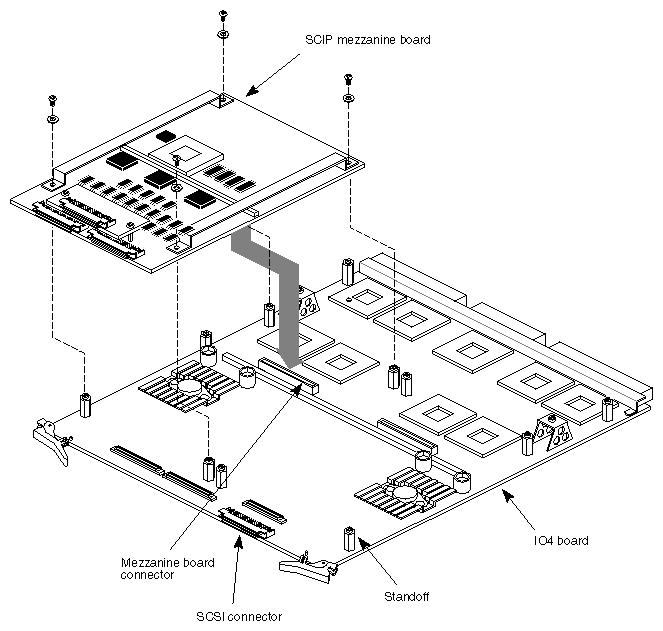
The S1 or SCIP mezzanine boards attach to the IO4 baseboard through four standoffs. An IO4 board can house up to two mezzanine boards. Follow these procedures to install or remove a mezzanine board:
Remove the IO4 board from the system.
Orient the SCSI mezzanine board so that the I/O channels face the same direction as the IO4 baseboard channels, then line the holes on each corner of the mezzanine board with the applicable standoffs (see Figure 2-5).
Press down on the mezzanine board so that the connector underneath engages the connector on the IO4 board.
Secure the mezzanine board to the IO4 baseboard using the truss-head screws.
Note: The mezzanine board may appear to fit very loosely on the IO4 baseboard. This is normal. The mezzanine boards are designed to "float" on the standoffs.
With the additional internal SCSI cables (up to 42 within the chassis), you must be extra careful to route the additional cables so that you can properly close the I/O panel door without damaging the cables or connectors.
| Note: The overcrowded cabling condition is not a problem in an ATM-intensive configuration. However, there is a potential cabling problem when you add SCSI cables to a system that already has a high number of internal SCSI cables. |
Figure 2-6 shows how to route the excess SCSI cabling into the cavity well in front of the cardcage. This prevents the cable from bunching up directly in back of the I/O panel door.
Create an adapter identification for the mezzanine board. The identification has the format S-XX-5 (S for SCSI) for the lower slot and F-XX-6 (F for F-chip mez) for the upper slot, where XX is the slot number where the IO4 board resides. For example, a mezzanine board in the upper position (IO adapter 6) on the main IO4 board located in slot 15 is labeled F-15-6.
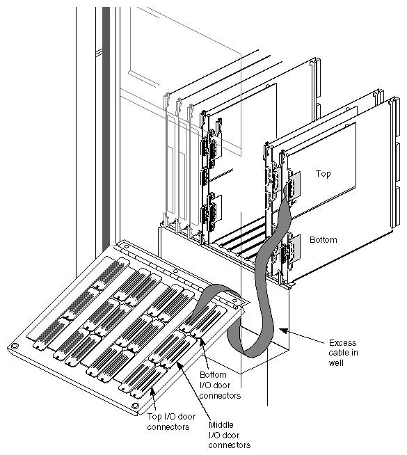
| Caution: To prevent damage to the SCSI cables by possible overstretching, always install the SCSI cables from the top of the IO4 board or top mezzanine board to the middle or lower row of connectors on the I/O door, as shown. If you connect a SCSI cable from the top of the IO4 board (or the top mezzanine board) to the top I/O door connectors, the cable could get overstretched, when the I/O door swings down to the fully open position. |
Software patches may be required to help support your new system configuration. Check the patch server at patches.csd or the patch Web page at the following location: http://www-cse.csd.sgi.com/Projects/patches/
Execute the hinv command to determine if the additional hardware is recognized by the system.
| Note: When you attach SCSI devices (such as a CD-ROM) to the additional IO4 boards, these devices are recognized by hinv only at the operating system level, and not at the PROM level. Only those devices that are attached to the master IO4 in slot 15 are recognized at the PROM level |
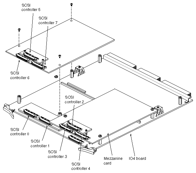
You can address the additional buses with the same method used for existing SCSI channels as described in this section. An IO4 board with two SCSI mezzanine boards can have up to eight SCSI bus interfaces or channels (see Figure 2-7).
The PROM drive addressing format is dksc(a,b,c), where a represents the SCSI bus number, b refers to the drive number, and c refers to the drive's partition number. The dksc designation is the monitor's name for SCSI.
| Note: The PROM can address only the master IO4 board in a system. In a rackmount system, the master IO4 resides in slot 15. If you need to address a drive connected to another IO4 board, you must do so under IRIX. |
Under IRIX, the format for addressing drives is /dev/dsk/dksSSSdD1LsP, where /dev/dsk references the IRIX file directory of the drives and dks designates SCSI. The SSS designator represents the slot number of the IO4 board and/or the SCSI bus number, dD refers to the drive number, 1L is the LUN (logical unit number, see Note below), and sP refers to the drive's partition number.
| Note: The number 10 has been omitted as a LUN and is addressed using /dev/dsk/dksSSSdDsP. |
If you are addressing a drive on the master IO4 board system, you need to specify only the applicable SCSI bus number. If you are addressing a drive on another IO4 board, you must specify both the slot number of the board and the applicable SCSI bus number.
For example, if you are addressing a drive connected to an IO4 board in slot 15 and SCSI bus number 5 (on a deskside system), the SSS number would be 155.
If SSS is a two- or three-digit number, the first one or two digits identify the IO4 board, by the Ebus slot number. The final digit identifies which of the eight possible SCSI buses (0 through 7) on the IO4 board is used. See Figure 2-7 to see how the buses are physically laid out on the IO4 board.
The software drive identification number uses the same form as the addressing scheme described earlier. Use the IO4 board slot number and/or the SCSI bus number, followed by the drive number and partition number as required.
Assume that you want to address partition 0 on SCSI drive (number 6). This drive connects to SCSI bus number 6. You can also assume that the IO4 resides in slot number 15 in a rackmount system.
The PROM drive address is dksc(6,6,0).
Assume that you want to address partition 0 on SCSI drive (number 6). This drive connects to SCSI bus number 6. You can also assume that the IO4 resides in slot number 14.
The IRIX drive address is /dev/dsk/dks146d6s0.