You can now configure a CHALLENGE XL or POWER CHALLENGE XL system with up to six IO4 boards. This increased I/O capability enables file servers to more effectively mirror large filesystems, and video servers to provide a higher number ATM data streams to better support video on demand (VOD) applications. A fully configured SCSI setup can provide up to 42 SCSI channels or buses, and a fully configured ATM setup can provide up to 12 ATM channels.
To install up to six IO4 boards, you must observe the configuration restrictions that are described in the following sections and summarized in Figure 1-1.
 | Caution: Be sure that the system has sufficient +5 VDC power to support the additional IO4 boards. Power issues are discussed in Section 1.5 and Section 1.6. |
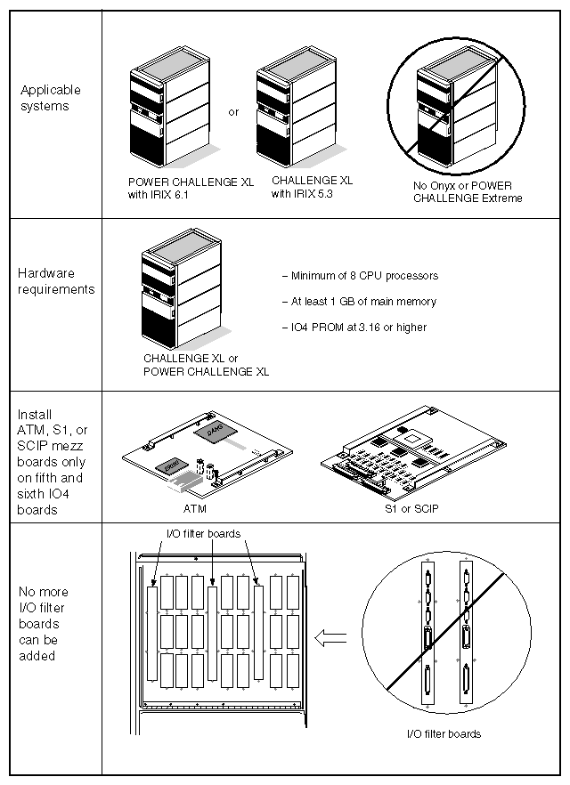
The system must adhere to the hardware and software requirements described in Table 1-1 to help assure optimal performance.
Table 1-1. System Hardware and Software Prerequisites
Category | Requirements |
|---|---|
System type | CHALLENGE XL or POWER CHALLENGE XL server systems only–no graphics configurations (see Caution below). |
Operating system requirements | IRIX 5.3 with required patches, or IRIX 6.1 |
Number of CPUs | Minimum of eight CPU processors (R4400™ or R8000™) |
Amount of main memory | At least 1 GB of main memory (highly recommended) |
IO4 PROM version level | 3.16 or higher (3.17 is recommended) |
| Caution: You cannot install more than four IO4 boards into an Onyx™ rackmount or a POWER CHALLENGE XL Extreme configuration (with the visualization console option). Silicon Graphics does not support more than four IO4 boards in any graphics configuration. |
Table 1-2 lists whether or not a particular I/O device is supported through the 5th and 6th IO4 boards.
Table 1-2. Supported and Nonsupported I/O Devices on the 5th and 6th IO4 Boards
I/O device | Supported on 5th and 6th IO4 boards? |
|---|---|
ATM mezzanine board | Yes |
SCSI mezzanine board | Yes (S1 or SCIP) |
Additional I/O filter boards (see Figure 1-2) | No. Therefore, you cannot add additional Ethernet, serial, or parallel ports through the 5th and 6th IO4 boards. (See Note and Caution below.) |
FDDI | No |
HIPPI | No |
There are no new support restrictions placed on the first four IO4 boards. The first four IO4 boards can continue to operate as they always have.
 | Note: The 5th and 6th IO4 boards do not support I/O filter boards due to a space limitation on the I/O door. The maximum number of I/O filter boards that a rackmount system can support is four (including the main I/O filter board). |
| Caution: Be sure not to reconfigure the software to support additional Ethernet, serial, or parallel ports beyond the maximum number provided through the first four IO4 boards. Otherwise, the system panics when it boots. |
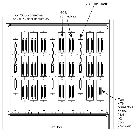
| Note: There is a two-port ATM connector plate and a single-port ATM connector plate that are available with the ATM option kit. See Table 1-3 for additional connector plate knockout information. |
Table 1-3. I/O Panel Connections per I/O Device
I/O Device | Interfaces or connectors per device | Knockouts used per interface or connector | Knockouts used per device |
|---|---|---|---|
SCSI on IO4 BOARD | 2 | 1/2 | 1 |
SCSI mezzanine | 3 | 1/2 | 1 1/2 |
FDDI mezzanine | 2 | 1 | 2 |
ATM | 1 | 1 | 1 |
EPLEX | 8 | 1/4 | 2 |
HIPPI | 2 | 1/2 | 1 |
The additional fifth and sixth IO4 boards provide expanded SCSI and ATM connectivity as described in Table 1-4.
Table 1-4. Maximum Configurations
Category | Number |
|---|---|
Maximum number of SCSI buses | 42 buses from a combination of six IO4 boards and 10 SCSI boards |
Maximum number of SCSI mezzanine boards | 10 on 5 IO4 boards (Note: SCSI mezzanine boards cannot be installed on all 6 IO4 boards because there are not enough connector knockout panels available on the I/O door, see Figure 1-2.) |
Maximum number of SCSI bulkhead connectors | Up to 40 SCSI bulkhead connectors on the I/O door. (Note: There are a maximum of 21 I/O connector knockout panels on the I/O door (see Figure 1-2). Twenty of these connectors are taken up by the SCSI ports--2 per connector knockout. The remaining connector knockout can be used for ATM connectivity. |
Maximum number of ATM (asynchronous transfer mode) mezzanine boards | 12 boards on 6 IO4 boards. (Note: The ATM uses the DANG chip. The software supports a maximum of 12 DANG interrupt vectors.) |
| Caution: IRIX 6.1 does not support ATM capability. |
Table 1-5 shows the various maximum configurations for systems with six IO4 boards.
Table 1-5. Allowable Configurations with Six IO4 Boards
Original configuration (with 4 IO4 boards) | Number of additional SCSI (S1 or SCIP) | Number of additional ATM | Results |
|---|---|---|---|
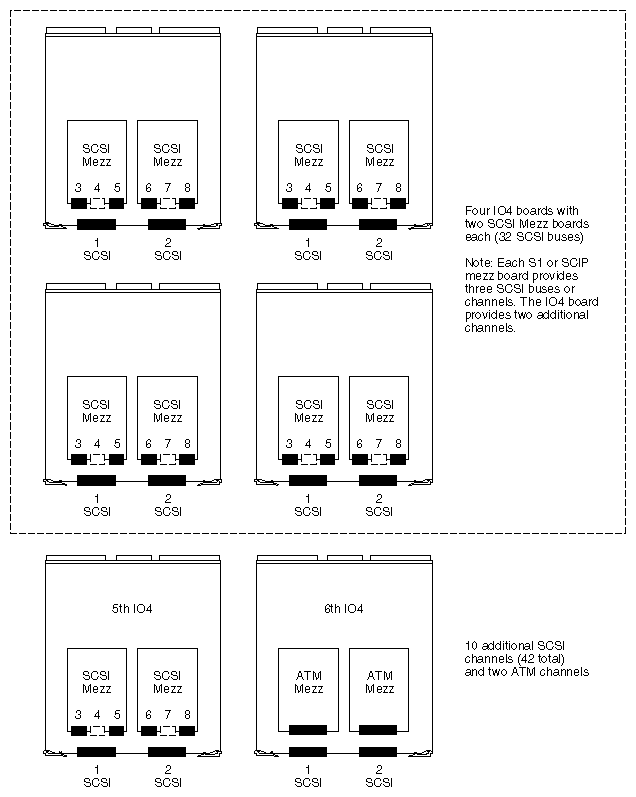
4 IO4 boards with 2 SCSI mezz cards each | 2 SCSI mezzanine on 1 IO4 board | 2 cards on 1 IO4 board | 42 SCSI buses (2 are internal) and 2 ATM channels (see Figure 1-3) |
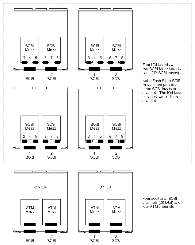
4 IO4 boards with 2 SCSI mezz cards each | N/A | 4 cards on 2 IO4 boards | 36 SCSI buses and 4 ATM channels (see Figure 1-4) |
3 IO4 boards with 2 SCSI mezz cards each and 1 IO4 board with 2 ATMs | N/A | 4 cards on 2 IO4 boards | 28 SCSI buses (2 internal) and 6 ATM channels (see Figure 1-5) |
1 IO4 board with 2 SCSI mezz cards and 3 IO4 boards with 2 ATMs | N/A | 4 cards on 2 IO4 boards | 18 SCSI buses and 10 ATM channels (see Figure 1-6) |
1 IO4 board with 1 SCSI mezz card and 1 ATM and 3 IO4 boards with 2 ATMs | N/A | 4 cards on 2 IO4 boards | 15 SCSI buses and 11 ATM channels (see Figure 1-7) |
4 IO4 boards with 2 ATMs (8 total) | N/A | 4 cards on 2 IO4 boards | 12 SCSI buses and 12 ATM channels (see Figure 1-8) |
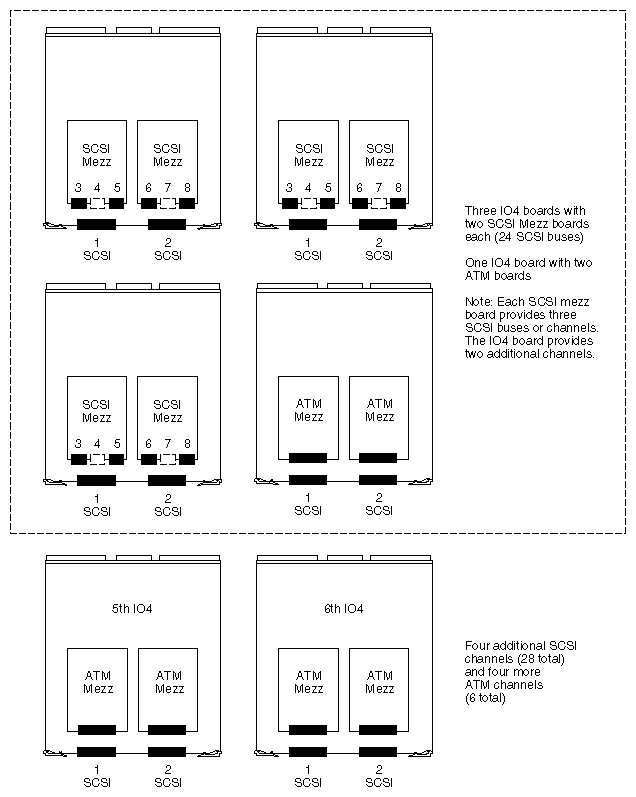
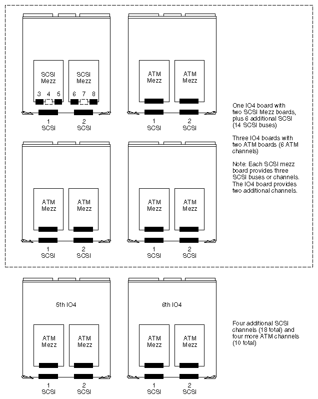
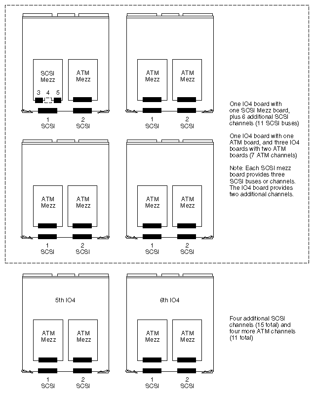
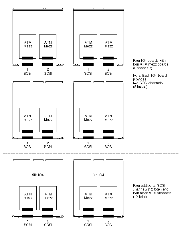
The boards in cardcages 1 and 2 are allotted a maximum of 1000 watts of 5 VDC power that are provided through the standard two OLS (off-line switching) power supplies and a set of power boards (see Table 1-6). Of the 1000 watts, approximately 200 watts (5 VDC) may be set aside for VME support in cardcage 2. Cardcage 3 provides approximately 1400 watts of 5 VDC power primarily to support VME connectivity.
| Caution: Do not exceed the designated power allotment when you are configuring a system. |
Table 1-6. OLS and Power Board Configurations for Rackmount Systems
System Configuration | OLSs Installed | Power Boards Installed |
|---|---|---|
CHALLENGE XL or POWER CHALLENGE XL | 2 | 3 (one 512, one dual 505, one System Controller) |
CHALLENGE XL or POWER
CHALLENGE XL with | 3 (requires 3-phase power) | 7 (two 512, one dual 505, three 505, one System Controller) |
Before you install the additional IO4 boards and mezzanine cards, make sure that the system has sufficient remaining power to support the new configuration. Use the information in Table 1-7 to help determine the power budget for your system. To get you started, Table 1-8 provides an example of a power budget for a six IO4 board configuration.
Table 1-7. 5 VDC Power Consumption Chart for Various System Boards
Board Type | Power Consumption at 5 VDC |
|---|---|
Master IO4 board and VCAM | 130 watts |
Slave IO4 board | 47 watts |
Slave IO4 board with 2 ATMs | 121 watts |
S1 mezzanine board | 20 watts |
SCIP mezzanine board | 20 watts |
F-chip mezzanine board | 35 watts |
FDDI mezzanine board | 25 watts |
ATM board | 37 watts |
HIPPI board | 75 watts |
VMEbus board (five slots in cardcage 2) | Approximately 200 watts (see Note below) |
| Note: As stated earlier, the VME boards in cardcage 2 are allotted approximately 200 watts of 5 VDC power. Normally, 40 watts is allowed per VME slot in cardcage 2. However, it is possible to exceed this power rating. See Appendix A for further information. |
Table 1-8. Six IO4 Boards With Maximum ATM Configuration and VMEbus Boards
Configuration | Power Consumption at 5 VDC |
|---|---|
Master IO4 board (slot 15) with VCAM and two ATM boards | 204 watts |
Five slave IO4 boards (in slots 13, 11, 9, 7, and 5) with two ATM mezzanine cards on each IO4 board | 605 watts (Note: Each slave IO4 board with two ATM mezzanine cards uses 121 watts.) |
Four 40-watt VME boards | 160 watts |
Total | 969 watts (must be less than or equal to 1000 watts) |