This chapter describes the hardware and software installation procedures to install and configure an array. The entire installation process takes approximately 12 hours to complete.
 | Note: The POWER CHALLENGEarray requires IRIX 6.1 or later. The POWER CHALLENGEarray 10000 and the CHALLENGE DataArray require IRIX 6.2 or later. In addition the Array 2.0 software release requires IRIX 6.2 or later. |
The array is a multilayered configuration, composed of systems called array nodes. Software and hardware extensions provide extra array functionality. Because the fundamental component of the array is the node server, much of the array installation process is similar to a single server installation.
As the array is installed, each array node evolves through various stages of functionality, each of which can be independently tested. The stages include:
single isolated server with hardware tested (base node)
single server operating on local area network (LAN node)
single server operating on HIPPI network (HIPPI node)
fully operational node (array node)
The general array installation procedure is as follows (see also Figure 4-1 and Figure 4-2).
Obtain preinstallation information (see Table 3-1 in Chapter 3).
Position the major hardware components (see Section 4.3).
Bring up the IRISconsole (see Section 4.4).
Bring up individual array nodes (see Section 4.5).
Bring up and test local HIPPI (see Section 4.6.1 and Section 4.6.4).
Bring up the local area network (see Section 4.7).
Cable and configure the HIPPI network, and test network (see Section 4.8).
Install, configure, start, and test the array-specific features (see Section 4.9).
Install other Silicon Graphics application software (see Section 4.10).
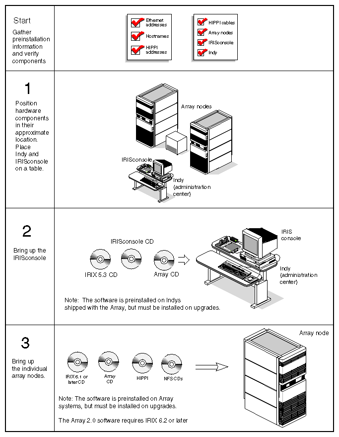
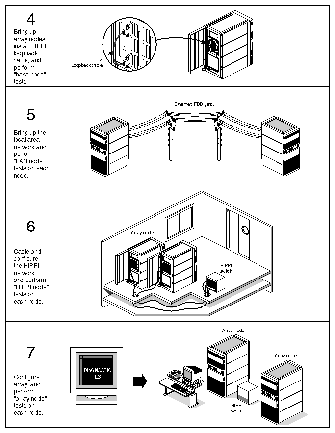
At this point the preparatory steps have been completed. Verify that the preconfiguration checklist in Table 3-1 in Chapter 3 is complete before you begin the actual installation. The following information, Section 4.3 through Section 4.10, provides specific information on installing and configuring an array.
After the hardware has arrived and has been inventoried, and once the floor planning has been completed, you can position the array nodes, the Indy workstation, and any HIPPI switch and graphics monitors at their planned locations.
Do not perform any cabling or additional hardware configuration at this point.
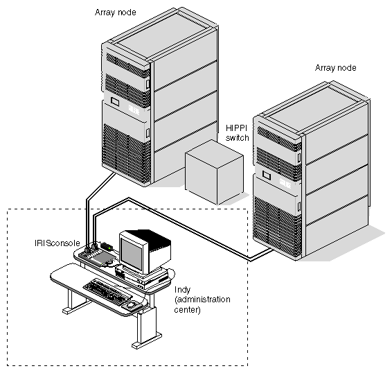
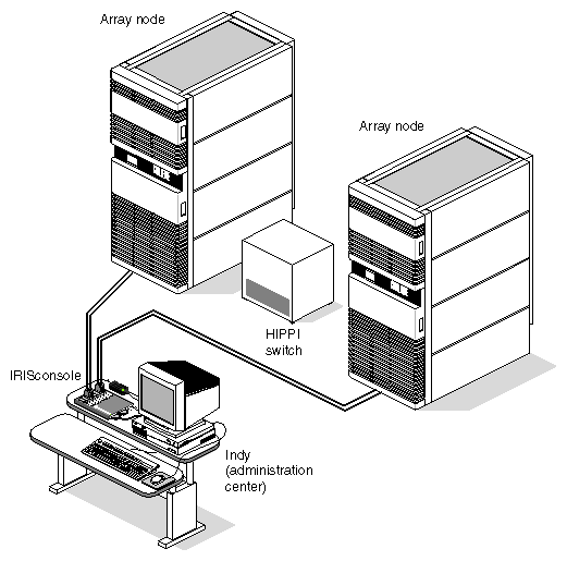
The IRISconsole connects the remote system console port and diagnostic port of each array node to a single Indy workstation through a multiplexer box, as an alternative to connecting an ASCII terminal to each array node (see Figure 4-3). This enables the IRISconsole to act as a centralized console for all array node servers, making it much easier to bring up a large array. Furthermore, the IRISconsole provides additional server management features not present on ASCII terminals, such as the ability to power cycle and reset sets of systems with a click of a button.
Since the IRISconsole is the centralized console for all array node servers, set up the IRISconsole first. Once the IRISconsole is operational, you can bring up the individual array nodes.
The IRISconsole is set up in several stages:
Set up the Indy hardware.
Connect the Serial port multiplexer to the Indy.
Install IRIX 5.3, IRISconsole, and array software as required.
Connect the IRISconsole to the array nodes.
Configure the array nodes with IRISconsole.
Add the nodes to the IRISconsole array site.
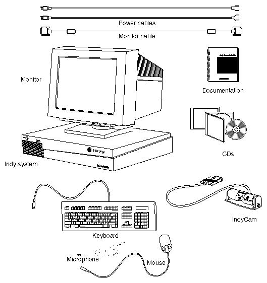
The Indy workstation provides the graphical interface for array system administration. Figure 4-4 shows the individual components for the Indy workstation. See the Indy Workstation Owner's Guide (p/n 007-9804-xxx) for complete information on setting up the Indy.
| Note: If you are modifying existing systems into an array, you must make sure that you have an IRIX 5.3 CD for the Indy system. |
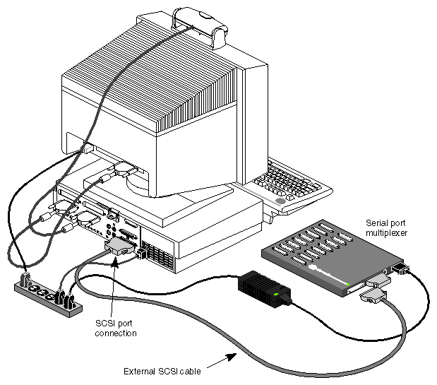
The high-performance serial port multiplexer (SPM) acts as an integral part of the IRISconsole station (see Figure 4-5). This section provides brief information on connecting the SPM to an Indy workstation. For complete instructions, consult the IRISconsole ST-1600 Multiplexer Installation Guide (p/n 007-2839-xxx).
Obtain the serial cables needed to connect the SPM (P/N 018-0527-001) to the site's target systems.
Connect the serial port multiplexer to the Indy workstation's SCSI port, as shown in Figure 4-5.
Attach the other end of the cable to the leftmost socket on the back of the multiplexer, as shown in Figure 4-5.
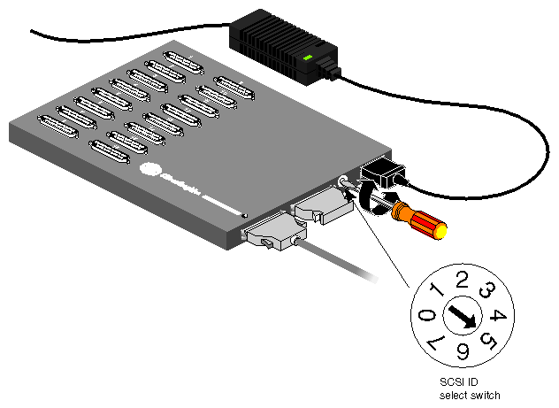
Select an appropriate SCSI ID number by inserting a small screwdriver or other tool into the SCSI ID select switch and rotating the arrow, as shown in Figure 4-6. A commonly used SCSI ID for the multiplexer is 5. Using SCSI ID 7 on early models of the multiplexer causes the power indication LED to blink. Select another ID and the LED glows steadily with no blink.
Note: Ensure that you select a unique SCSI ID for the multiplexer. The system disk in the Indy workstation is always SCSI target ID 1, so never select SCSI ID 1 for the multiplexer. If the multiplexer is the last SCSI device on the Indy workstation's standard external SCSI port, it must be properly terminated.
Reboot the Indy workstation.
Follow these instructions to install software on the Indy.
| Note: If the customer purchased a complete array package, all the required software should already installed at the factory. |
Install IRIX 5.3 with XFS and perl software (if not already installed) from the IRIX CD on the Indy.
Note: You may need to provide this software on CD if it is not already installed. Install the IRISconsole software from the IRISconsole CD.
Install the array services software from the array CD.
Note: Be sure to install only the IRIX 5.3 version of the array services software on the Indy. For the Array 1.0 software release, these files are: arraysvcs.sw.client53
arraysvcs.man.client53
For the Array 2.0 release, these files are:
arraysvcs_53.man.base (Array services 2.0 man pages for IRIX 5.3)
arraysvcs_53.sw.aview (ArrayView visual array monitor)
arraysvcs_53.sw.client (Array Services client software for IRIX 5.3)
arraysvcs_53.sw.dso (Array Services libraries for IRIX 5.3)
Verify that you have the array services and perl software installed on the Indy, by entering the following commands:
# versions arraysvcs
You should see a display similar to the following:
I arraysvcs 03/25/96 Array Services 2.0 I arraysvcs.man 03/25/96 Array Services Documentation I arraysvcs.man.client53 03/25/96 Array Services man pages for IRIX 5.3 I arraysvcs.sw 03/25/96 Array Services Software I arraysvcs.sw.client53 03/25/96 Array Services client software for IRIX 5.3 |
# versions eoe2
Look for the following output line:
I eoe2.sw.gifts_perl 07/27/95 Perl Software |
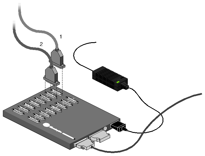
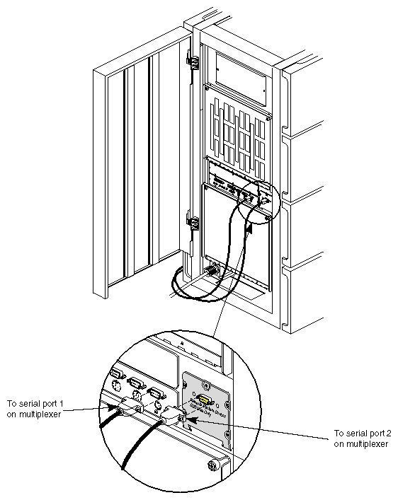
You can use the IRISconsole to interact with the array nodes, which is to be brought up shortly. You first need to connect the IRISconsole to the array nodes (as shown in Figure 4-7 and Figure 4-8), and then configure the IRISconsole to associate particular multiplexer ports with particular array nodes.
This section summarizes the steps to connect the SPM to the Array nodes. For additional information, see the IRISconsole ST-1600 Multiplexer Installation Guide (p/n 007-2839-xxx). Follow these general steps to connect the nodes to the SPM.
Connect the 25-pin end of a serial cable to port 1 on the multiplexer, and connect another serial cable to port 2. See Figure 4-7 for an example.
Connect the 9-pin connector from serial port 1 on the multiplexer to the connector labeled System Console tty_1 on the I/O panel of the array node.
Connect the 9-pin connector from serial port 2 on the multiplexer to the connector labeled Remote System Control SSE Use Only on the panel to the right of the I/O panel on the array node (see Figure 4-8).
Note: Older rackmount and deskside systems may not have the Remote System Controller panel shown in Figure 4-8. If this panel is not present, see the System Controller PROM Upgrade for Oracle Parallel Servers Guide (p/n 108-0140-xxx) for information on installing one. Repeat these steps to connect additional array nodes to the SPM used as part of the IRISconsole.
Now that the IRISconsole is operational, you need to register the array nodes comprising the array with the IRISconsole.
Autoconfig and reboot the Indy system.
Bring up the IRISconsole to determine that the software is working properly by typing:
/usr/sbin/ic
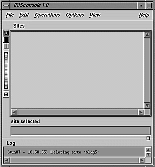
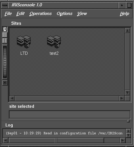
You should get the IRISconsole main menu shown in Figure 4-9.
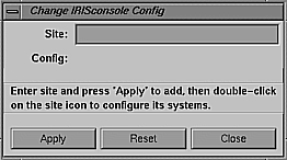
From the Edit menu, choose "Add New Site..." The Change IRISconsole Config dialog box appears, as shown in Figure 4-10.
In the Site: field, type in the name of the user's array, for example, hotbox.
Click the Apply button.
The name of the configuration file appears in the Config: field; its name is based on the site name. For example, /var/IRISconsole/.icrc.netwk1 is the configuration file for the site netwk1. The format of this filename, .icrc.sitename, cannot be changed.
When you see "New site <site name> added, click OK.
Close the site window by clicking the Close button. If you wish to add more array sites, repeat steps 4 through 8.
To save these changes, choose "Save IRISconsole Config" from the File menu. The file is saved to the IRISconsole directory, /var/IRISconsole/.
Go to Section 4.4.6 when you are done creating array sites.
| Note: You can rename or delete a site using choices in the IRISconsole main window Edit menu. |
To register a array node in the IRISconsole site, follow these steps:
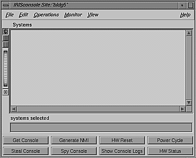
In the IRISconsole main window, double-click on the site to which you want to add a system (or select the system and choose "Open Site..." from the Operations menu). The site window opens, as shown in Figure 4-11.
In the site window, choose "Add New System..." from the Edit menu. If IRISconsole security is on, you are prompted for your password.
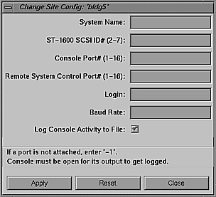
After you enter your password, the Change Site Config dialog box appears, as shown in Figure 4-12.
In the System Name: field, type the hostname of the array node you want to add to this site; for example, hotbox1.engr.sgi.com.
In the SPM SCSI ID#: field, enter the SCSI ID number of the SPM.
Based on port assignments that were designated in Section 3.6, "Assign IRISconsole Ports for Each Array Node," enter the SPM port numbers to which cables to the Console port and Remote System Control port are connected in the Console Port# and Remote System Control Port# fields, respectively.
In the Login: field, enter the user name (login) under which all operations requiring access to the system via the network can be performed. This login is the one used in the command:
rsh <login>@<system> /usr/etc/sysctlrd -p
In the Baud Rate: field, enter the baud rate at which this system sends data to IRISconsole; the default for the array node is 9600. If you enter a different baud rate, be sure that the node has been configured for that rate.
Click the box at the Log Console Activity to File: if you want console activity logged to a file in the /var/IRISconsole/logs/console_logs/ directory that has the format <systemname>.<timestamp>.log. The format of this filename cannot be changed.
Note: To view a log of a system's console activity (Spy Console button or command) or to view console activity logs (View Console Logs button or command), this box must be checked when the system is added to a site. When you are satisfied with the settings for this system, click the Apply button to add this system to the site.
To save the configuration, choose "Save Site Config" (or "Save Site Config As...") in the site window File menu.
To add another system to the site, edit the entries in the fields of the Change Site Config dialog box, or click the Reset button to clear all entries and begin entering again. Follow instructions in steps 3 through 10 for the new system.
When you are finished adding systems to the site, close the Change Site Config dialog box by clicking the Close button.
If your hardware configuration changes, use "Modify System Config..." in the site window Edit menu to change the parameters for a system in a site. To delete a system from a site, select it in the site window and choose "Delete Selected" in the Edit menu.
Exit from the IRISconsole.
You have now created the array through the IRISconsole. Verify the configuration by following the steps outlined in this section. Make the required changes as applicable, if the configuration is not accurate.
Open the main IRISconsole window by typing /usr/sbin/ic as superuser. You should see a display similar to Figure 4-13 that shows the name of the newly created array. Figure 4-13 shows two arrays, one called "LTD," the other called "test2."
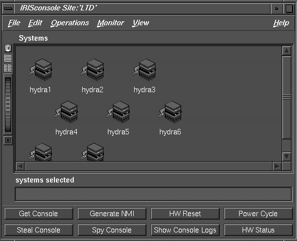
Click on the array icon. You should see a display similar to Figure 4-14 that shows the individual nodes of the array. In this example, array "LTD" is expanded into the eight array nodes called "hydra1" through "hydra8."
Open up a node by clicking on one of the array node icons (for example, hyra1 in Figure 4-14).
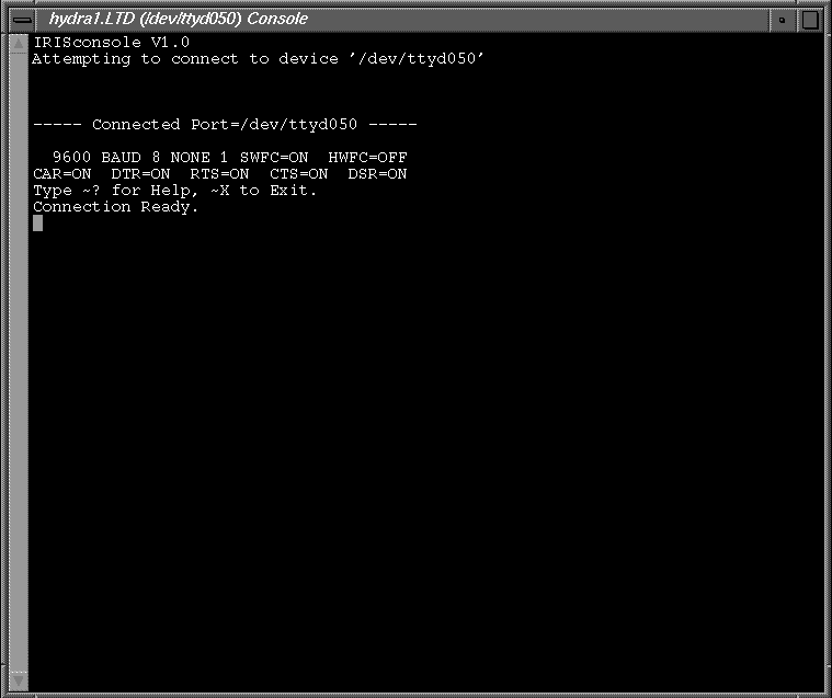
Click on Get Console in the array node menu to get a display similar to the one shown in Figure 4-15. This window represents the console shell of the selected array node.
At this point, your IRISconsole can manage the nodes of the array. You can now begin to bring the array nodes up to their first stage of array evolution, the "base node" stage.
Section 4.6 through Section 4.9 describe how to bring up each node of the array, first as a basic, standalone system (base node), then as a node in a LAN (LAN node), next as a node in a HIPPI network (HIPPI node), and finally as a node in an array configuration (array node).
Bring up the nodes first as individual array node servers, without any array-specific features, to simplify the installation process. If is required, you will install the HIPPI interfaces, IRIX 6.1 or later (see Note below), HIPPI and NFS software. Afterward, you must configure the local area network, then bring up and test the systems.
| Note: The POWER CHALLENGEarray requires IRIX 6.1 or later. The POWER CHALLENGEarray 10000 and the CHALLENGE DataArray require IRIX 6.2 or later. In addition the Array 2.0 software release requires IRIX 6.2 or later. |
For complete instructions on setting up the systems, consult one of the following manuals as applicable:
CHALLENGE/Onyx XL Rackmount Installation Instructions (p/n 108-7042-xxx)
CHALLENGE/Onyx XL Deskside Installation Instructions (p/n 108-7039-xxx)
POWER CHALLENGE to Extreme Graphics, and Onyx Extreme to RealityEngine2 Graphics Upgrade Installation Instructions (108-0117-xxx)
The first stage of array node bring-up involves installing the customer hardware, installing the base array software, and bringing the system up. During this stage, the goal is to eliminate any immediate hardware problems. At this point, the array node is not even operational on the network. You will interact with the nodes through the IRISconsole.
Here are the basic tests to set up a node for the array. Many of these steps are described in detail in this section.
Be sure the array nodes are properly positioned (see Figure 4-16).
Be sure array nodes are properly attached to the multiplexer, and the IRISconsole is configured.
Install any additional hardware and interfaces into the array nodes.
Set up and power on the array nodes.
Install the major software modules on each array node (as required).
IRIX 6.1 or later as applicable to the array configuration
Note: Be sure to install the perl software (eoe2.sw.gifts_perl), as well. NFS3
HIPPI
IRIX array services software and all other desired array software modules from the array CD.
Note: These software modules are preinstalled on all complete array configurations. Run base node diagnostics for the chassis to test the individual array node hardware and HIPPI interface (see Appendix A for additional information on diagnostic testing).
If the customer purchased a complete array configuration, the HIPPI board(s) should already be installed in the system at the factory. If you are upgrading existing server clusters into an array, you may need to install HIPPI boards and internal cabling. If this is the case, install these boards now.
The IRIS HIPPI Installation Instructions (p/n 108-0106-xxx) provides complete instructions on HIPPI hardware installation. Figure 4-17 shows the internal HIPPI hardware components.
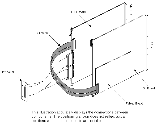
| Note: The HIPPI board set consists of a short F mezzanine board that resides on the IO4 and a 9U VME form factor board. |
If there is additional hardware the customer has ordered, but is not installed, install that hardware into the array nodes now.
Using the IRISconsole as the terminal interface, boot up the individual array nodes. Identify and rectify any immediate hardware problems. If the customer purchased a complete array package, you can skip Section 4.6.3 and proceed to Section 4.6.4. All the required software modules to operate an array are installed at the factory.
Now you can begin to install the bare minimum software release. If the customer purchased a complete array package, all the required software modules to operate an array (for example, IRIX operating system, array services NFS, and HIPPI) are installed at the factory. If you are converting existing systems into an array configuration, follow the software installation procedures outlined in this section.
To install IRIX 6.1 or later, follow these steps to boot the miniroot and install the operating system using the IRISconsole.
Verify that the CD-ROM drive is still attached to the system and then install the operating system CD in the drive.
At the System Maintenance Menu, select option 2, Install System Software.
You should see the following prompt:
Load software from local CD-ROM? (y/n) [y]
Press <Enter> to boot the miniroot from the CD-ROM drive.
After a while, you see the Inst> prompt. A default set of subsystems is selected for installation. You may wish to add or delete subsystems depending upon your customer's needs.
After you have selected the appropriate subsystems, enter go at the Inst> prompt.
Install any application CDs as required.

Caution: Verify that the customer system has all the required replacement software applications to run on the new version of the operating system. Otherwise, you could receive an error similar to the following when you boot the system:
incompatible SW products
If this occurs and you do not have the replacement application software, you need to remove the existing application.Verify that the perl software are installed on each node by typing:
versions eoe2.sw.gifts_perl
You should receive a confirming output line, if this module is present.
Note: This software must be present for the array configuration to operate properly.
Install the HIPPI software through the miniroot, as required. To check if HIPPI software is present, type:
versions hippi
The display then indicates whether or not the software is installed.
| Note: If the customer purchased a complete array configuration, the software is installed at the factory. |
Install the NFS software through the miniroot, as required. To check if NFS software is installed, type:
versions nfs
| Note: If the customer purchased a complete array configuration, the software is installed at the factory. |
Install the desired array software through the miniroot, as required. There are a number of available array software modules. The customer needs to determine which modules are applicable to his or her configuration.
| Note: If the customer purchased a complete array configuration, the software is installed at the factory. |
| Caution: Be sure to install the IRIX 6.1 or later version of the array services software on the array node. Do not attempt to install the IRIX 5.3 version on an array node, or software conflicts will arise. |
Verify that the array services software is installed on each node by typing:
versions arraysvcs
You should receive the confirming output lines if this module is present.
| Note: This software must be present for the array configuration to operate properly. |
You may be required to install additional software patches from the patch CD. This should generally be done after you have installed the main IRIX CD.
The patch software installs through the miniroot. Follow these steps to select a patch for installation:
At the Inst> prompt, enter:
Inst> install patchSGxxxxxxx
where xxxxxxx is the number of the patch you wish to install.
Caution: You must specify each required patch, since you cannot install all the patches at one time. For example, if you give the command install default, you see the error desktop_tools.sw.tools requires desktop_eoe.sw.fam 1019999999. Select the desired patches for installation.
Once all the patches are installed, enter quit to exit from Inst.
After you have installed all the system software, follow these instructions to complete and verify proper operating system and array software installation:
Reboot the system and watch the display messages carefully to verify a normal boot process.
Log in and enter the following command to verify the installation and that the operating system is IRIX 6.1 or later:
uname -a
If uname reports that the system is running the IRIX 6.1 or later for an array node, the installation is successful.
Once the HIPPI software is installed, you can test the interfaces on each of the nodes using a loopback cable as described in this section.
Connect a loopback cable between the source and destination of each HIPPI interface.
Note: Any HIPPI cable can be used as a loopback cable. However, specially made, short testing cables are available for easier hookups. Run the hiptest program to test the interface. To test the first HIPPI interface (/dev/hippi0), use the command:
hiptest -D/dev/hippi0
To test the second HIPPI interface (/dev/hippi1), use the command:
hiptest -D/dev/hippi1
Refer to hiptest reference page (type man hiptest), or the IRIS HIPPI Installation Instructions (p/n 108-0106-xxx) for more information about hiptest, loopback cables, and fault diagnosis.
The array nodes are now at the base node stage of evolution. You can perform a full base node diagnostic using the array test diagnostic. Leave loopback cables attached, and execute the base node test on each node:
/usr/array/diags/arraytest -stage base_node |
At this point, the array nodes should all be successfully running as unnetworked "base nodes." You can now bring the nodes up on the network.
Connect the local area network to the array nodes. For most sites, this is an Ethernet network. Configure each array node to operate as a conventional networked server on the local area network. See the IRIX Admin:Networking and Mail manual (p/n 007-2860-xxx) for additional information.
Ensure that the array nodes can ping each other.
Execute the LAN node test. Test the local area network by running the array test diagnostic with the -lan_node option on each array node. Specify the hostnames of all the array nodes on the command line. For example, for an array with hostnames hotbox1 through hotbox4, run the diagnostics on each node as:
/usr/array/diags/arraytest -stage lan_node hotbox1 hotbox2 hotbox3 hotbox4 |
See Appendix A for additional information on diagnostic testing.
You can begin cabling the nodes into the array's HIPPI network once the following tasks are done:
The array nodes are stabilized and are up on the local area network.
The HIPPI interfaces have passed the loopback tests on all base nodes.
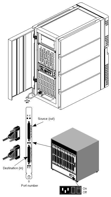
The Multi-Port switch (see Figure 4-18) from Essential Communications provides up to 32 HIPPI ports; two ports—destination (in) and source (out), are required for each HIPPI connection. The array uses a maximum of 16 ports (in the eight-node configuration). For additional information on the HIPPI switch, see Multi-Port Switch manual.
Cable the array nodes into the HIPPI network by connecting node interfaces to the HIPPI switch, or directly to the other interface for switchless arrays. Run the cables under a raised floor if possible. Power on the HIPPI switch when you are done.
| Note: A common cabling failure is to reverse source and destination ports (see Figure 4-19). If you are using a HIPPI switch, the middle row of LEDs on the switch light up if both source and destination cables are wired correctly. |
| Caution: Do not remove HIPPI connectors at an angle, or pins can be easily bent. Check the pins for alignment if there are suspected HIPPI problems. |
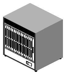
Figure 4-19 illustrates how to connect an array node to the HIPPI switch.
| Note: Because it is easy to miscable the network, make sure to label both ends of each cable with a unique cable identification number as described in Section 3.7.2. Carefully follow the HIPPI networking diagram you prepared earlier. Be sure to label the cables according to the port number on the HIPPI Switch (see Figure 4-19). |
After connecting the nodes to the HIPPI switch, plug the HIPPI Switch into the power source and turn it on (see Figure 4-19). Consult the Multi-Port Switch manual or Chapter 2 for power issues as required.
Configure the HIPPI network as described in the IRIS HIPPI Administrator's Guide (p/n 007-2229-xxx). This typically involves the following steps:
Edit /usr/etc/hippi.imap to define the endpoint I-Fields.
Edit /etc/config/netif.options to associate the HIPPI interfaces with IP network names.
Edit /etc/hosts (or other hostname resolution mechanism) to bind HIPPI IP network names with HIPPI IP addresses.
| Note: You can copy and paste using the Indy mouse in IRISconsole windows to quickly replicate information for each of the nodes. |
The HIPPI bypass option is available only on Array 2.0 HIPPI distribution software and is automatically installed when the array software is loaded. This option enables the application to communicate directly with the HIPPI adapter rather than using the operating system to move packets between the adapter and the application program. Because the operating system overhead is eliminated or bypassed, packet latency is significantly reduced. You can specify up to eight jobs (or applications) for bypassing for each HIPPI interface (board).
| Note: MPI 2.0 requires two bypass jobs for each MPI job. Thus, there is a maximum of four MPI jobs that can use the bypass job option. |
| Caution: HIPPI bypass requires HIPPI board p/n 030-0522-007 (or later) for proper operation. If you are not sure of the board revision level, check the chip part number at board location H1I7. It should be 74ALS808A (or later). If the part number is 74AS808, you need to get an updated HIPPI board. |
There are several bypass control options available—see the hipcntl reference (man) page for additional information. Consult with the array administrator to determine how these bypass (bp) fields should be set.
Execute the hipcntl commands as root using the format hipcntl <hippi#> <bypass option>. Here is an example using the bpstatus (bypass status) option. This command provides status information on bypass packets sent and received over a given HIPPI interface. The <hippi #> specifies the interface number to be checked. If you do not specify the HIPPI board or interface number, the command defaults to HIPPI 0.
As root, type in the command hipcntl hippi0 bpstatus. You should get display similar to the following:
Job 0: IDLE
Job 1: IDLE
Job 2: BUSY
Job 3: IDLE
Job 4: IDLE
Job 5: IDLE
Job 6: IDLE
Job 7: IDLE
Bypass ulp : 144
Bypass max jobs : 8
Bypass max ports : 1024
Bypass max src pages : 1024
Bypass max dst pages : 1024
SRC descriptors : 456314483
SRC packets : 549519990
SRC bytes : 4390184105472
SRC desc err: ifield : 0
SRC desc err: bufx : 0
SRC desc err: opcode : 0
SRC desc err: addr : 0
SRC err: job disabled : 0
DST descriptors : 456314491
DST packets : 549520689
DST bytes : 4390195410816
DST err: port disabled: 6
DST err: job disabled : 0
DST err: no buffs : 0
DST err: inv bufx : 0
DST err: inv auth : 0
DST err: inv offset : 0
DST err: inv opcode : 0
DST err: inv version : 0
DST err: inv seq num : 0
By default, bypass device-special files are created for two HIPPI interfaces only. These are /dev/hippibp00[0 - 7] and /dev/hippibp10[0 - 7]). The numbers 00 and 10 in hippibp00 and hippibp10 are the interface numbers in decimal. The numbers [0-7] are the virtual device number or job numbers. If the array node has more than two HIPPI interfaces, you must use the mknod command to create the rest of the bypass character special files for the /dev directory.
Here is an example using the mknod command to create additional HIPPI interface /dev files (see also the mknod reference man page).
To create the /dev files for HIPPI bypass interface 201, where 2 (or 20) is the interface or device number and 1 is the job number, you need to insert the proper variables for the mknod command:
/sbin/mknod <name> b | c <major number> <minor number>
This example uses these variables or arguments.
The <name> is hippibp201.
The argument "c" designates the HIPPI character device.
The number 251 is the major number.
Note: The number 251 is always used as the major number for HIPPI devices.
Use this formula to determine the minor number:
interface_num * 4096 + bp_offset (2048) + bp_job_num
To find the minor number for HIPPI bypass interface 201, multiply 2 (which is the interface number) times 4096, add the bypass offset number 2048, and then add the bypass job number, 1. Your answer should be 10241.
As root, type in the command:
mknod /dev/hippibp201 c 251 10241
Check the /dev directory to determine if the new HIPPI bypass device was created.
The system administrator needs to be familiar with the upper limits settable by the various hipcntrl bypass control commands (such as hipcntl bpspages) to suit the resource usage at the site (see also the hipcntl reference page). The hipcntl status/bpstatus commands lists the current settings.
| Note: Resource usage is the amount of system memory that the bypass can pin. The worst case amount of physical memory that can be pinned (or used) is: #jobs * [(max-source-pages + max -destination-pages) + 1] * 16384 bytes = maximum memory used |
Test the HIPPI network by running the array test diagnostic with the -stage hippi_node option on each array node. Specify the hostnames of all the array node on the command line. For example, for an array with hostnames hotbox1 and hotbox2, run the diagnostics on each node as:
/usr/array/diags/arraytest -stage hippi_node hotbox1 hotbox2 |
At this point, you now have a cluster of array nodes, communicating via the local area network and the HIPPI network. The final stage occurs when you create the array using the IRISconsole and configure the array services software.
The arrayconfig command performs three major tasks to activate the array:
It builds the array services daemon configuration file (arrayd.conf).
It ships the arrayd.conf file to the specified array nodes in the array.
It starts the array services daemons on the specified array nodes in the array.
You can execute arrayconfig from the Indy using the following command structure:
/usr/etc/arrayconfig [-a arrayname] [-m] [-d] host...
The following example uses "LTD" as the array name with hosts, hydra1 through hyrdra4.
/usr/etc/arrayconfig -a LTD -m -d hydra1 hydra2 hydra3 hydra4
If the array configuration is successful, the following confirmation statement is displayed:
Configuration of array <arrayname> complete |
Test the array services configuration by running the array test diagnostics on each of the POWER nodes as follows:
/usr/array/diags/arraytest -stage array_node
Read the array release notes for information on running other diagnostic tests on the array. The array reference pages provide information on the available array commands.
In addition, see Getting Started with the Array Guide (p/n 007-3058-xxx) for information on running the Rend Asunder demo program.
On a complex configuration such as an array, you should also perform some "live testing." The additional testing may add significantly to the installation time, but this step is highly recommended. Live testing means on having preferably "friendly" users test the array with real-life applications.