This chapter describes the activities required to prepare for the arrival and installation of the array. The information presented here is intended to augment the CHALLENGE/Onyx Site Preparation Guide (p/n 108-7040-xxx).
The array consists of the following major hardware components:
Rackmount or deskside systems
Indy workstation
Serial Port Multiplexer (SPM)
Multi-Port HIPPI switch
This chapter provides site preparation information primarily for the various array configurations, as well as the Indy, the SPM, and the HIPPI switch. The CHALLENGE/Onyx Site Preparation Guide does not cover these platforms. This chapter also covers site preparatory information for the array nodes, but only as it relates to the array.
For complete site preparation and planning information on the array node systems, consult the CHALLENGE/Onyx Site Preparation Guide.
Due to the number of hardware and software components that make up an array, the installation is significantly more complex and different from other Silicon Graphics products. As a result, managing customer expectations for the installation becomes a key factor towards assuring a successful array bring-up process. Significant issues regarding the customer expectations and the installation are:
The array is a high-profile and important product for the customer due to the cost. Identify the array decision makers in the customers' organization, and involve them in the planning and naming of the array and nodes.
Unlike the installation of a complex network of workstations and servers, where individual nodes coming online signal progress, an array may not provide the customer needed functionality until the installation is complete. Be sure to let the customer know about this condition.
This section includes preinstallation information for SSEs.
It is recommended least one of the SSEs have a strong background in HIPPI installation, configuration, and network administration. This helps to assure an efficient and timely installation.
It is also recommended that two SSEs perform the installation. More than two can be involved in the bring-up process. However, the following situations may occur:
There may not be enough installation activities to keep more than two SSEs continually occupied during the array bring-up. The additional SSEs must then observe rather than participate in the installation.
Depending on the size of the installation site, there may not be enough room for more than two SSEs to work efficiently or effectively during the array bring-up.
The following steps are suggested as a guide for the installation planning process:
Read and study related materials (see "Related Documents"). You can expect that product information may change and evolve significantly in future releases.
Contact other SSEs who have installed an array for tips and warnings. Also check the array Web pages; see "Related Documents" for the Web locations.
If possible, schedule a dry run of the installation. This familiarizes you with the procedures and prepares you for the next step.
Meet with the customer to develop an installation plan. See Table 2-1 and Section 3.1, "Before You Begin Installation," for pointers on how to develop a plan. This helps to get the customer oriented to the process as well as to make decisions that affect the efficiency and success of the installation effort. Decisions regarding node names, network addresses, and so on should be mapped out in detail as a part of the meeting. It is amazing how much time and trouble such seemingly trivial details can cost.
Once you have developed an installation plan, set up the array site, and received, uncrated, and positioned the hardware components in their approximate locations, the actual installation (cabling, booting, software installation, configuration, and testing) takes 12 or more hours to complete.
Because of the number of hardware components involved, planning for an array configuration is a very involved task. Be sure to perform the tasks in Table 2-1 and pay particular attention to the special array setup activities that are called out.
Some sites require specialized knowledge to plan and install services such as power and safety equipment. Always follow local and regional codes and recommendations while performing activities under regulation. When using consultants, verify that they are licensed and knowledgeable about local regulations.
Site preparation also involves thinking about the future. As configurations grow, site requirements change. While planning a site, consider how and when a site will need modification, and plan accordingly.
To minimize mistakes and unforeseen situations for complex sites, assign one person as a coordinator to read this guide and assign tasks. Table 2-1 is only a guideline and cannot cover all circumstances involved in site preparation. Also, many activities are interdependent and involve compromises. After the coordinator evaluates the dependencies and compromises, this guide can be divided among several people so that activities can be performed at the same time.
Start with the activities that take the longest time. Pay particular attention to activities that involve dependency on others, such as having an electrician install power circuits.
When you have completed the activities outlined in Table 2-1, the site is prepared and is ready to receive the system. To proceed, read Section 2.6, "Preparing to Receive the Array," then continue to the installation instructions provided for the system. See the "Introduction," for a list of related documents.
Table 2-1. Site Preparation Checklist
Activity | Date | Notes |
|---|---|---|
Prepare to receive shipment | __/__/__ |
|
Required tools | __/__/__ |
|
Size and weight of shipping cartons | __/__/__ |
|
Assistance for moving large objects | __/__/__ |
|
Prepare physical location | __/__/__ |
|
System chassis | __/__/__ |
|
Raised floors - highly recommended for array configuration | __/__/__ |
|
Indy workstation and Serial Port Multiplexer (IRISconsole) location. Note: It is recommended that these be placed on a desk or table. | __/__/__ |
|
Local devices: monitor, keyboard, mouse | __/__/__ |
|
Expansion chassis | __/__/__ |
|
Multi-Port HIPPI switch |
|
|
Check environmental conditions | __/__/__ |
|
Air conditioning | __/__/__ |
|
Electrical interference (EMI, ESD) | __/__/__ |
|
Vibration | __/__/__ |
|
Acoustics | __/__/__ |
|
Site safety | __/__/__ |
|
Install power | __/__/__ |
|
Determine power requirements | __/__/__ |
|
Install power circuits | __/__/__ |
|
Install safety and protection equipment | __/__/__ |
|
Prepare cabling for local devices | __/__/__ |
|
Monitors | __/__/__ |
|
Terminals | __/__/__ |
|
Input devices | __/__/__ |
|
Serial devices | __/__/__ |
|
Parallel devices | __/__/__ |
|
Networks (Ethernet and HIPPI) | __/__/__ |
|
Printers | __/__/__ |
|
Modems | __/__/__ |
|
HIPPI cables | __/__/__ |
|
Obtain IP addresses and serial numbers | __/__/__ |
|
HIPPI addresses | __/__/__ |
|
Ethernet address | __/__/__ |
|
Host names for systems | __/__/__ |
|
System serial numbers | __/__/__ |
|
It is highly recommended that an array be installed in a raised-floor room primarily because of the thick HIPPI cables.
 | Note: The cutouts in the floor should be large enough to accommodate the width of the HIPPI cable pairs. In addition, the cables are heavy. A pair of HIPPI cables weigh approximately 23 lbs (10.4 kg). |
Using the clearance guidelines in this section, select a location that allows proper airflow, cabling, routine activities, and maintenance. As a general rule, use these guidelines to ensure the best system performance. All systems include thermal overrides to prevent damage caused by excessive heat, but an improperly positioned system leads to unnecessary service calls and system downtime.
Every location and system is different, requiring flexibility during installation. This section provides minimum space guidelines for a fully loaded system. The space guidelines can be reduced by 10 to 20 percent for:
systems that are not fully configured, depending on the number and type of devices installed in the chassis
Silicon Graphics systems arranged next to each other
The final test for any system is actual operation, and some adjustments may be required after initial installation.
To determine the minimum space requirements for a chassis, add the chassis dimensions shown in Figure 2-1 and the appropriate clearances shown in Table 2-2.
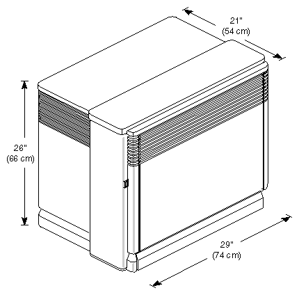
Table 2-2. Deskside Airflow Clearances
Top Clearance | Left Side[a] | Right Sidea | Front | Back |
|---|---|---|---|---|
More than 6" | 3" (8 cm) | ≥ 6" (15 cm) | ≥ 6" (15 cm) | ≥ 6" (15 cm) |
Less than 6" | 6" (15 cm) | ≥ 10" (25 cm) | ≥ 8" (20 cm) | ≥ 8" (20 cm) |
[a] As viewed from the front of the chassis | ||||
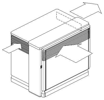
The different clearances are based on the airflow requirements of the chassis. If the top of the chassis is unobstructed, less clearance is required on the sides and back. If the top of the chassis is obstructed, however, the sides and back of the chassis must compensate for the smaller air exhaust path. Figure 2-2 shows the airflow path of the chassis.
Additional space is required to service the chassis, such as connecting or disconnecting cables and changing internal drives, boards, and other components. Be sure to allow sufficient space either in front of or behind the chassis to facilitate future installation, service, and cabling activities. The chassis includes wheels for easier front-to-back movement. See Figure 2-3 for the wheel locations. You can fix the wheels in place by using the chassis levelers or by using a wheel chock (Silicon Graphics part number 040-0220-001).
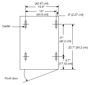
Table 2-3. Deskside Physical Specifications
Parameter | Characteristic |
|---|---|
Dimensions, chassis |
|
26" (66 cm) | |
21" (53.3 cm) | |
29" (73.7 cm) | |
Dimensions, shipping |
|
Height | 37" (94 cm) |
Width | 32" (81.3 cm) |
Depth | 42" (107 cm) |
| |
195 lbs (88.5 kg) | |
300 lbs (136 kg) | |
Shipping | 325 lbs (147 kg) |
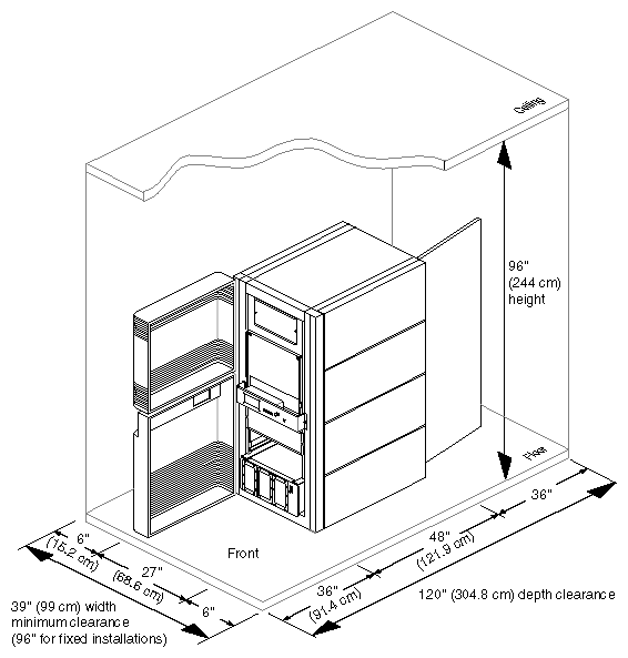
Provide a location for a rackmount chassis, with clearance for the front and rear cabinet doors in their fully opened positions. The chassis requires minimal side clearances because most of the airflow and servicing is through the front, rear, and top of the chassis. Side access is required to:
remove and install a midplane
remove and install a SCSI box
For activities requiring side access, determine if the chassis can be rolled forward or backward to provide adequate side clearance. If an installation is semipermanent, such as at sites with chassis bolted directly to the floor to prevent movement, allow a total width of 96 inches (244 cm). Use the dimensions shown in Figure 2-4 for rackmount chassis clearance.
Position the chassis so that it receives proper air circulation. See Figure 2-5 for the airflow through the chassis. An ideal location provides cool air near the chassis air intake vents and warm air removal near the chassis air outlets. Air temperature should not fluctuate dramatically, and the air should circulate freely.
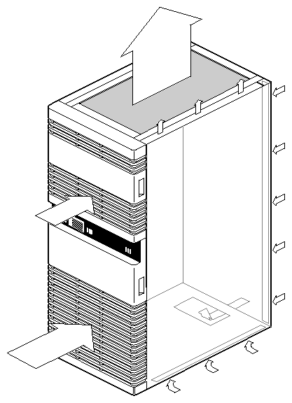
| Note: Keep the top of the chassis clear of any obstruction. The top of the chassis is the primary air venting surface and is not structurally designed to hold weight. |
Compare the floor-load rating of the site with the values listed in Table 2-4. Some site floor-load ratings are as low as 100 lb/ft2 To ensure that the flooring is adequate for all future chassis upgrades, you must make sure the floor-load rating meets 133 lb/ft2.
Table 2-4. Rackmount Floor-Load Requirements
Chassis Configuration | Weight | Floor-Load Rating (lb/ft.2) |
|---|---|---|
Minimum | 560 lbs (254 kg) | 62 lb/ft2 (249 kg/m2) |
Maximum | 1,200 lbs (544 kg) | 133 lb/ft2 (533 kg/m2) |
For installations on raised floors, check that the construction will properly support the distribution of the weight. The rackmount chassis uses four casters and four stabilizing levelers that distribute the weight load to the site floor. See Figure 2-6 for the caster and leveler locations. If a floor is modified, such as by cutting new access panels in computer floor tiles, determine if additional reinforcement is required.
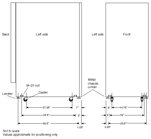
Table 2-5. Rackmount Physical Specifications
Parameter | Characteristic |
|---|---|
Dimensions, chassis |
|
62.3" (159 cm) | |
27" (69 cm) | |
48" (122 cm) | |
Dimensions, shipping |
|
height | 74.5" (189 cm) |
width | 46" (117 cm) |
depth | 59.5" (151 cm) |
| |
560 lbs (254 kg) | |
1,200 lbs (544 kg) | |
1,500 lbs (680 kg) | |
| |
height | 15" (38 cm) |
width | 17.345" (44 cm) |
depth | 19" (48.3 cm) |
Table 2-6. Indy Workstation Physical Specifications
Parameter | Characteristic |
|---|---|
Dimensions, chassis |
|
3" (7.6 cm) | |
16" (41 cm) | |
14" (35.5 cm) | |
| |
16 lb (7.3 kg) |
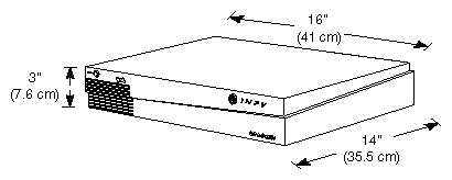
Table 2-7. IRISconsole Physical Specifications
Parameter | Characteristic |
|---|---|
Dimensions, chassis |
|
1.2" (3.1 cm) | |
11" (28.1 cm)) | |
8.1" (20.6 cm | |
| |
Typical | 3.8 lbs (1.7 kg) |
Shipping | 14 lbs (6.4 kg) |
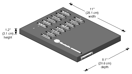
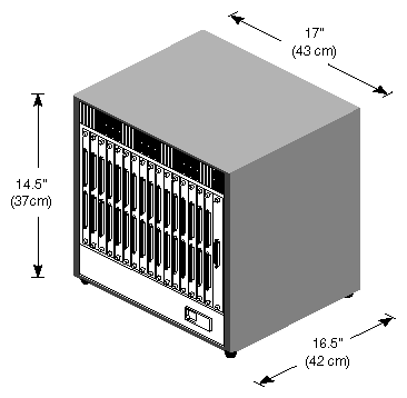
Table 2-8. Multi-Port HIPPI Switch Physical Specifications
Parameter | Characteristic |
|---|---|
Dimensions, chassis |
|
14.5" (37 cm) | |
17" (43 cm) | |
16.5" (42 cm) | |
| |
40 lb (18 kg) |
This section defines the space required for the following array configurations:
two-system configuration (no HIPPI switch)
two-system configuration (with HIPPI switch)
four-system configuration (with HIPPI switch)
eight-system configuration (with HIPPI switch)
Figure 2-10 shows the space requirements for a two-node configuration without the Multi-Port HIPPI switch. This figure shows the maximum spatial configuration using rackmount systems. To determine spatial requirements for a deskside system, see Section 2.5.1.
| Note: With this two-node configuration, you need to add a HIPPI switch before you can upgrade to a larger array setup. |
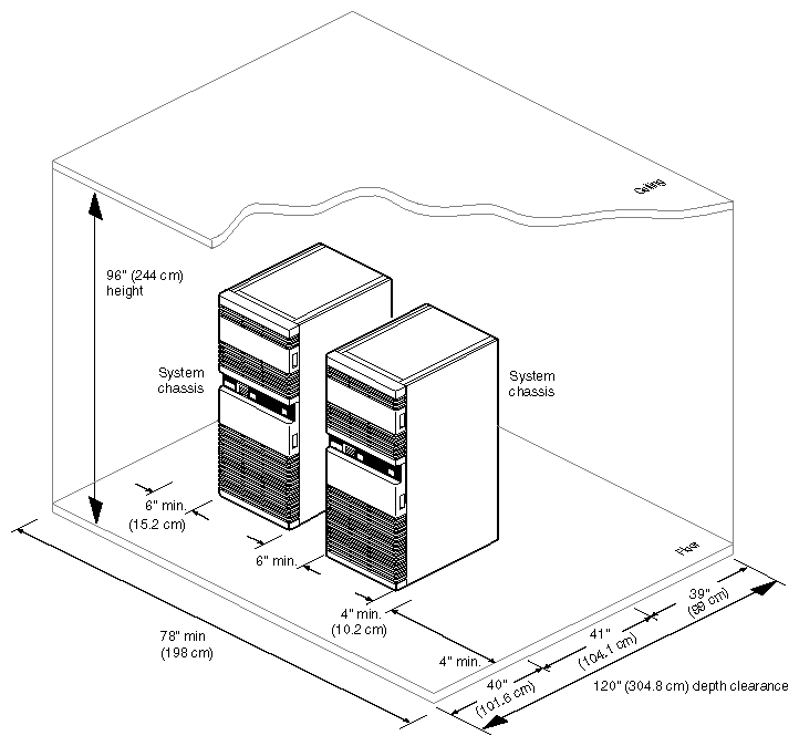
Figure 2-11 shows the space requirement for a two-node configuration with a HIPPI switch. This figure shows the maximum spatial configuration using rackmount systems. To determine spatial requirements for a deskside system, see Section 2.5.1.
| Note: With this two-node configuration, you can directly upgrade to a four- or eight-node setup by adding systems and array software. |
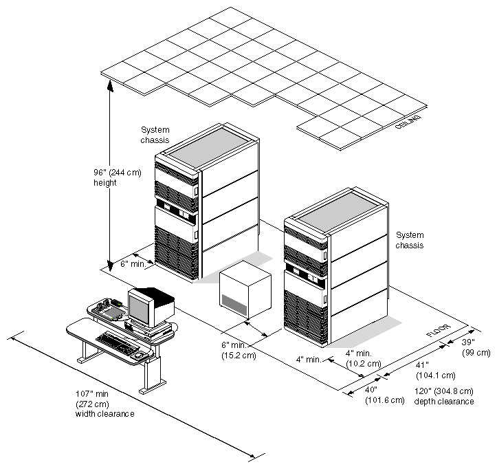
| Note: Be sure to add the IRISconsole station space requirements to your final calculations. Figure 2-11 does not include a table/desk measurements for the IRISconsole. |
Figure 2-12 shows the space requirements for a four-node configuration. This figure shows the maximum spatial configuration using rackmount systems. To determine spatial requirements for a deskside system, see Section 2.5.1.
| Note: The four-node array requires a HIPPI switch for operation. |
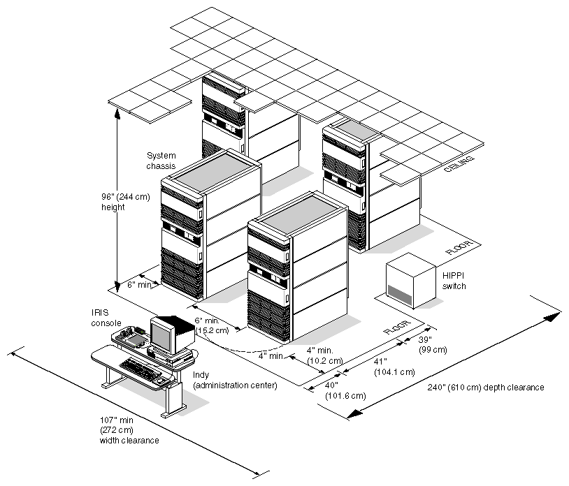
| Note: Be sure to add the IRISconsole space requirements to your final calculations. Figure 2-12 does not include table/desk measurements for the IRISconsole. |
Figure 2-13 shows the space requirements for an eight-node configuration. This figure shows the maximum spatial configuration using rackmount systems. To determine spatial requirements for a deskside system, see Section 2.5.1.
| Note: The eight-node array requires a HIPPI switch for operation. |
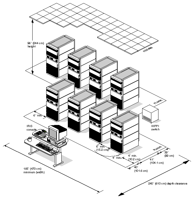
| Note: Be sure to add the IRISconsole station space requirements to your final calculations. Figure 2-13 does not include table/desk measurements for the IRISconsole. |
To prepare for the arrival of a system, plan these activities:
Obtain tools required to receive and install equipment.
Arrange assistance for moving large and/or heavy cartons and crates.
Check the path to the system's destination.
Use Table 2-9 to determine the tools required for each listed activity.
Table 2-9. Tools Required for Receiving and Installing Systems
Activity | Component | Tools Required |
|---|---|---|
Unloading crates and boxes | Deskside | Pallet jack (up to 300 lbs) |
| Rackmount | Forklift (can require up to a 1,500 lb capacity) Note: A forklift or the lift gate on a truck is required to unload the system from a vehicle. Afterwards, you can use a pallet jack to transfer the systems within a building. |
| Indy workstation and SPM Multiplexer | Hand truck/dolly (approximately 20 lb load) |
| Monitors | Hand truck/dolly (approximately 50 to 80 lb load) |
| Multi-Port HIPPI switch, Indy workstation, SPM Multiplexer | Hand truck/dolly (approximately 40 lb load) |
Opening shipping cartons or crates | Deskside | Knife (to cut strapping bands) wrench, 7/16" or adjustable |
| Rackmount | Gloves (protection from crate splinters) pliers (for stuck fasteners) |
| Monitor, destination kit, Indy workstation, Serial-port multiplexer, Multi-Port HIPPI switch | Knife (to cut packing tape) |
Moving system |
| Low-profile dolly that keeps chassis vertical; moving blankets or wraps |
Installing chassis |
| Under normal circumstances, no tools are required; for adding optional components, medium slothead and cross-recess screwdrivers may be required |
Connecting cables |
| Small slothead and cross-recess screwdrivers |
Stabilizing chassis (seismic protection) | Rackmount, Vault | Stabilizers, 2.5" length minimum, to fit one of two types of nuts on the chassis underside: 1) 1/2-13 UNC (Unified National Coarse) 2) M-20 |
Assistance is required to receive a shipment, uncrate a chassis, and move a chassis. The rackmount chassis requires assistance to unbolt and remove the crate's front panel and to remove the chassis from the crate. It also requires assistance to move any distance.
Always use assistance when moving equipment up or down ramps. For rackmount systems, use a minimum of three individuals. On fully configured systems, up to five people may be required to safely move the chassis. Avoid ramps that exceed a 20° angle.
Walk through the proposed route for moving a system to its destination. Pay particular attention to corners, ramps, restricted doorways, low ceilings, and fixed obstructions. Table 2-10 shows the shipping dimensions of the main containers.
Table 2-10. Shipping Dimensions
System | Shipping Dimensions |
|
|
|---|---|---|---|
| Height | Width | Depth |
Deskside | 42" (107 cm) | 32" (81.3 cm) | 37" (94 cm) |
Rackmount | 74.5" (190 cm) | 46" (117 cm) | 59.5" (152 cm) |
For installations above or below ground floor, check that the system is within the size and weight limits of elevators or similar cargo machinery. If freight blankets are available, use them on elevator sides. Use straps to keep the chassis from shifting while being moved in an elevator.
For uncrated deskside chassis, the wheels work well on smooth surfaces but are not designed for carpeting and rough flooring.
Check your site for these environmental factors:
air conditioning
electrical interference (EMI, ESD)
vibration
acoustics
safety
Each site must provide proper air temperature, humidity, and filtration. Use Table 2-11 through Table 2-17 to prepare the site air conditioning.
| Note: Temperature ranges apply to systems inside a building and out of direct sunlight. For installations at or above 8,000 feet, the system fans must be set on high-speed during operation. |
Table 2-11. Deskside Environmental Specifications
Parameter | Characteristic |
|---|---|
| |
Operating | 5 ° to 35° C at sea level5° to 30° C above 5,000 feet
|
Nonoperating | –20° to 60° C at sea level |
Heat dissipation (maximum configurations) |
|
8,100 Btu/hour (.68-ton AC load) | |
512 Btu/hour (.042-ton AC load) | |
| |
Operating | 10 to 80%, noncondensing |
Nonoperating | 10 to 95%, noncondensing |
| |
Operating | 10,000 feet MSLa, maximum |
Nonoperating | 40,000 feet MSLa, maximum |
aMSL indicates mean (average) sea level or 29.92" (76 cm) of mercury barometric pressure.
Table 2-12. Rackmount Environmental Specifications
Parameter | Characteristic |
|---|---|
Air temperature range |
|
Operating | 5° to 35° C at sea level |
Nonoperating | –20° to 60° C at sea level |
Heat dissipation (maximum configurations) |
|
Server and graphics chassis, 220V 1-phase | 16,000 Btu/hour (1.3-ton AC load) |
Server and graphics chassis, 220V 3-phase | 24,000 Btu/hour (2-ton AC load) |
Humidity range |
|
Operating | 10 to 80%, noncondensing |
Nonoperating | 10 to 95%, noncondensing |
Altitude |
|
Operating | 10,000 feet MSLa, maximum |
Nonoperating | 40,000 feet MSLa, maximum |
aMSL indicates mean (average) sea level or 29.92" (76 cm) of mercury barometric pressure.
Table 2-13. Indy Environmental Specifications
Parameter | Characteristic |
|---|---|
Air temperature range |
|
operating | 13° to 35° C |
nonoperating | –40° to 65° C |
Heat dissipation | 900 Btu/hour (1-ton AC load) |
Humidity range |
|
operating | 10 to 80%, noncondensing |
nonoperating | 5 to 95%, noncondensing |
Altitude |
|
operating | 10,000 feet MSLa, maximum |
nonoperating | 40,000 feet MSLa, maximum |
aMSL indicates mean (average) sea level or 29.92" (76 cm) of mercury barometric pressure.
Table 2-14. IRISconsole (SPM) Environmental Specifications
Parameter | Characteristic |
|---|---|
Air temperature range |
|
Operating | 0° to 55° C |
Nonoperating | –40° to 75° C |
Humidity range |
|
Operating or nonoperating | 0 to 95%, noncondensing |
Table 2-15. Multi-Port HIPPI Switch Environmental Specifications
Parameter | Characteristic |
|---|---|
Air temperature range |
|
Operating | 0° to 40° C |
Nonoperating | –30 ° to 85° C |
Humidity range |
|
Operating or nonoperating | 10 to 90%, noncondensing |
Altitude |
|
Operating | 10,000 feet MSLa, maximum |
Nonoperating | 40,000 feet MSLa, maximum |
Table 2-16 and Table 2-17 provide heat dissipation specifications for a rackmount and deskside array.
Table 2-16. Array Heat Dissipation (Rackmount Nodes)
Configurations |
|
|---|---|
Two nodes (220 V, 1-phase) | Approximately 33, 000 Btu/hour |
Two nodes (220 V, 3-phase) | Approximately 50,000 Btu/hour |
Four nodes (220 V, 1-phase) | Approximately 66,000 Btu/hour |
Four nodes (220 V, 3-phase) | Approximately 98,000 Btu/hour |
Eight nodes (220 V, 1-phase) | Approximately 130,000 Btu/hour |
Eight nodes (220 V, 3-phase) | Approximately 194,000 Btu/hour |
Table 2-17. Array Heat Dissipation (Deskside Nodes)
Configurations |
|
|---|---|
Two nodes (110 V) | Approximately 15,000 Btu/hour |
Two nodes (220 V | Approximately 18,000 Btu/hour |
Four nodes (110 V) | Approximately 28,000 Btu/hour |
Four nodes (220 V) | Approximately 34,000 Btu/hour |
Eight nodes (110 V) | Approximately 54,000 Btu/hour |
Eight nodes (220) | Approximately 67,000 Btu/hour |
The CHALLENGE/Onyx product line is designed for the typical office and computing environment, requiring no special modifications or protection. If a system is installed at an industrial site, check that vibrations are kept within the limits shown in Table 2-18.
Table 2-18. CHALLENGE/Onyx Vibration Limits
Description | Value |
|---|---|
CHALLENGE/Onyx |
|
Less than 5-10 Hz at 0.01" total excursion, 10-500 Hz at 0.1 g | |
Less than 5-10 Hz at 0.02" total excursion, 10-500 Hz at 0.1 g | |
8-33 Hz, depending on configuration | |
Indy |
|
Less than 5-19 Hz at 0.02" total excursion, 5-500 Hz at 0.25 g |
Check that the additional computer equipment acoustics (noise-emission levels) are within the limits for the particular site (see Table 2-19).
Table 2-19. Rackmount, Deskside, and Indy Acoustic Levels
Parameter | Level |
|---|---|
| |
typical | 57 dB |
maximum | 65 dB |
| |
typical | 60 dB |
maximum | 66 dB |
Indy |
|
typical | 36 dB |
| Note: Check local codes to ensure that the site is compliant with worker safety regulations, such as those provided by UL, TUV, and CSA. |
The systems are designed for computer rooms. The measurements in this section are only guidelines because acoustics depend on many factors outside the control of the manufacturer. Room characteristics such as carpeting and wall coverings affect the noise levels at an installation.
If a site exceeds desirable noise levels:
Reduce the amount of flat reflective surfaces such as glass, tile, or metal.
Add sound-absorbing carpet, wall coverings, and drapes.
Add sound baffles in critical locations and be careful not to block airflow.
Install ceiling tiles with sound-absorbing properties.
Modify office space to isolate operators and hardware.
This section lists the power specifications for the following array components:
Indy workstation (Table 2-20)
IRISconsole SPM multiplexer (Table 2-21)
CHALLENGE/Onyx systems (Table 2-22)
Deskside and rackmount array power consumption examples (Table 2-23 and Table 2-24)
For the power requirements of the array nodes, see Table 2-22 and the CHALLENGE/Onyx Site Preparation Guide.
Table 2-20. Indy Workstation Power Specifications
Parameter | Specifications |
|---|---|
Input voltage (US/Japan) | 100 to 132 VAC |
Input voltage (international) | 200 to 264 VAC |
Frequency | 47 to 63 Hz |
Current | 2.4 to 1.8 A (at 115 VAC) |
Table 2-21. SPM IRISconsole Power Specifications
Power Usage (Typical) | Specifications |
|---|---|
+5 VDC | 1500mA maximum, 1110 mA typical |
+12 VDC | 100mA maximum (full load), 1 mA (unloaded) |
All power requirements are provided by the standalone power supply included with the SPM. The power supply is auto-ranging and comes with a 110 VAC power cord in Japan and North America. All other destinations should use a 220 VAC rated power cord.
| Note: A fuse located at the rear of the HIPPI switch chassis is rated for 6 A at 250 VAC. |
Table 2-22. CHALLENGE and Onyx System Power Requirements
Description | Country | Power VAC input |
|
| Hertz |
| Phase | Rating | Power Supply |
|
|---|---|---|---|---|---|---|---|---|---|---|
|
| nom | min | max | min | max |
| amps | watts |
|
Deskside 110 VAC Nom | US/Japan | 110 | 100 | 132 | 50 | 60 | 1 | 16 | 1500 |
|
Deskside 95 VAC Nom | Japan | 90 | 85 | 132 | 50 | 60 | 1 | 16 | 1200 |
|
Deskside 220 VAC | US/Int'l | 220 | 187 | 264 | 50 | 60 | 1 | 13 | 1900 |
|
Rackmount 220 VAC 1P | US/Int'l | 208 | 187 | 264 | 50 | 60 | 1 | 24 | 3800 |
|
Rackmount 220 VAC 3P | US | 208 | 187 | 264 | 50 | 60 | 3 | 24 | 5700 |
|
Rackmount 220 VAC 3P | Int'l | 400 | 360 | 480 | 50 | 60 | 3 | 24 | 5700 |
|
| Note: See also the CHALLENGE/Onyx Site Preparation Guide. |
Table 2-23. Deskside Array Power Consumption
Array Configuration | Approximate Power Usage |
|---|---|
Two-node configuration, deskside array | 41 amps (total) |
Four-node configuration, deskside array | 71 amps (total) |
Eight-node configuration deskside array | 137 amps (total) |
Two-node configuration, deskside array (220VAC) | 33 amps (total) |
Four-node configuration, deskside array | 58 amps (total) |
Eight-node configuration deskside array | 110 amps (total) |
Table 2-24. Rackmount Array Power Consumption
Array Configuration | Approximate Power Usage |
|---|---|
Two-node configuration, rackmount array | 54 amps (total) |
Four-node configuration, rackmount array | 102amps (total) |
Eight-node configuration, rackmount array | 198 amps (total) |