| Note: Before installing an Oracle Parallel Server (OPS), make sure that the installation site meets the operating limits and AC power requirements as explained in Chapters 3 and 4 of the CHALLENGE/Onyx Site Preparation Guide. |
This chapter explains how to cable the two Challenge servers (OPS hosts), the two Challenge vaults, the Challenge RAID storage system, and the IRISconsole for use as the hardware for the Oracle Parallel Server. The process consists of
setting up the component systems
upgrading the Remote System Control firmware
upgrading the IO4 board mezzanine cards
planning the cabling
cabling the vaults to the OPS hosts
setting the OPS host SCSI IDs
installing the FDDI boards in the OPS hosts
cabling the Challenge RAID storage system to the Challenge servers
cabling the IRISconsole multiplexer to the workstation
cabling the IRISconsole multiplexer and the Challenge servers
powering on the systems
testing the installed OPS hardware
The following equipment is required for installation:
installation guides for the component systems (see the introduction to this guide for part numbers)
CHALLENGE/Onyx Site Preparation Guide (108-7040-040)
CHALLENGE/Onyx XL Rackmount Installation Instructions (108-7042-020)
CHALLENGE/Onyx Deskside Installation Instructions (108-7039-020)
FDDIXpress Mezzanine Board for CHALLENGE and Onyx Installation Instructions (document number 108-0116-002)
FDDIXpress Administration Guide (007-0813-040)
FDDIXpress Release Notes, included in FDDI board shipment
CHALLENGE RAID Installation and Maintenance Instructions (108-128-006)
IRIX Admin: Disks and Filesystems volume (007-2825-001)
Getting Started with XFS Filesystems (007-2549-001)
laptop or ASCII terminal
Phillips-head and small flat-blade screwdrivers
Read through the CHALLENGE/Onyx Site Preparation Guide before unpacking equipment at the site, paying particular attention to the following:
Make sure that the installation site meets the operating limits and AC power requirements as explained in Chapters 3 and 4 of the CHALLENGE/Onyx Site Preparation Guide.
Make sure required tools and personnel are on hand for unloading and opening crates and for moving large systems.
Prepare the physical location to allow for space, air flow, and floor-loading requirements for all component systems, as explained in Chapter 3 of the CHALLENGE/Onyx Site Preparation Guide.
Plan to situate the OPS component systems fairly close together. Differential SCSI cables, including cabling inside the chassis, can be no longer than 25 meters (82 feet). Use only the cables included in the shipment.
Make sure the site meets safety and operating considerations, as explained in Chapter 3 of the CHALLENGE/Onyx Site Preparation Guide. Note that the fully loaded Challenge RAID rack weighs 899.4 lb (407.96 kg); make sure flooring is adequate.
Prepare the site for the systems' electrical requirements, as explained in Chapter 4 of the CHALLENGE/Onyx Site Preparation Guide.
Connect your laptop or ASCII terminal and keyboard to the first Challenge server, as explained in the server installation instructions.
Reserve the label sheets that are included with the Challenge vault systems; you need them for labeling SCSI cables for OPS.
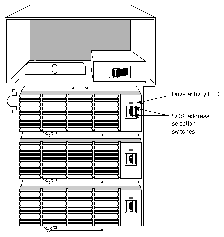
Set the SCSI bus selectors on each optional vault to 8 through 15. Figure 2-1 shows the location of the settings.
Connect the power cord for the first OPS host (OPS1). Turn on the main power switch on the back of the unit; turn on the laptop or ASCII terminal. If necessary, see the server installation instructions for details.
On the OPS host, turn the System Controller key switch to the On position. When power-on diagnostics are completed, a message appears.
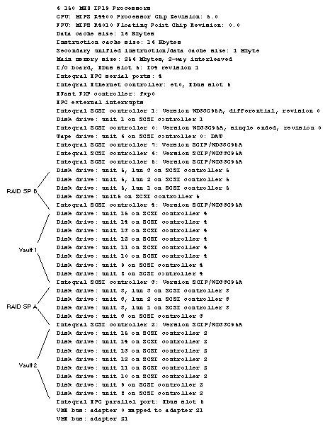
Type hinv on each OPS host; the screen should display output like the following (some lines omitted for clarity):
6 150 MHZ IP19 Processors
...
Integral Ethernet controller: et0, Ebus slot 5
FDDI ... : fxp0
EPC external interrupts
Integral SCSI controller 1: Version WD33C95A, differential, revision 0
Disk drive: unit 1 on SCSI controller 1
Integral SCSI controller 0: Version WD33C95A, single ended, revision 0
Tape drive: unit 6 on SCSI controller 0: DAT
Integral SCSI controller 7: Version SCIP/WD33C95A
Integral SCSI controller 6: Version SCIP/WD33C95A
Integral SCSI controller 5: Version SCIP/WD33C95A
Integral SCSI controller 4: Version SCIP/WD33C95A
Integral SCSI controller 3: Version SCIP/WD33C95A
Integral SCSI controller 2: Version SCIP/WD33C95A
Integral EPC parallel port: Ebus slot 5
VME bus: adapter 0 mapped to adapter 21
VME bus: adapter 21
Set up each system on the network for the site.
If necessary, install the Remote System Control port upgrade in one or both Challenge L systems, following instructions in the Remote System Control Port Installation Guide included in this shipment.
A new system controller firmware PROM is included in the OPS shipment. Install it as explained in the Remote System Control Port Installation Guide (0108-0140-001).
Two SCIP mezzanine cards are included in the OPS option. Install them following instructions in the CHALLENGE/Onyx XL Rackmount Installation Instructions or CHALLENGE/Onyx L Deskside Installation Instructions.
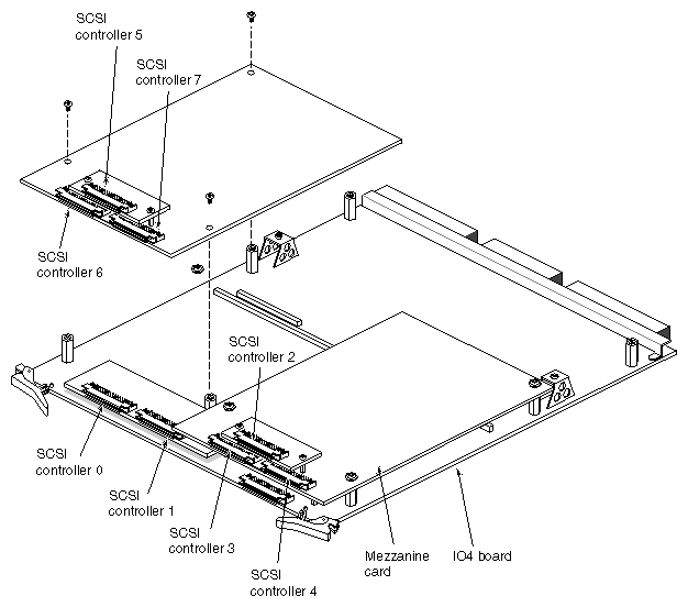
The numbering of SCSI controllers (ports) on the OPS host IO4 board and mezzanine card(s) (daughter boards), if present, is standardized. Figure 2-2 diagrams the numbering scheme. Note that the numbering is constant regardless of which daughter board is installed.
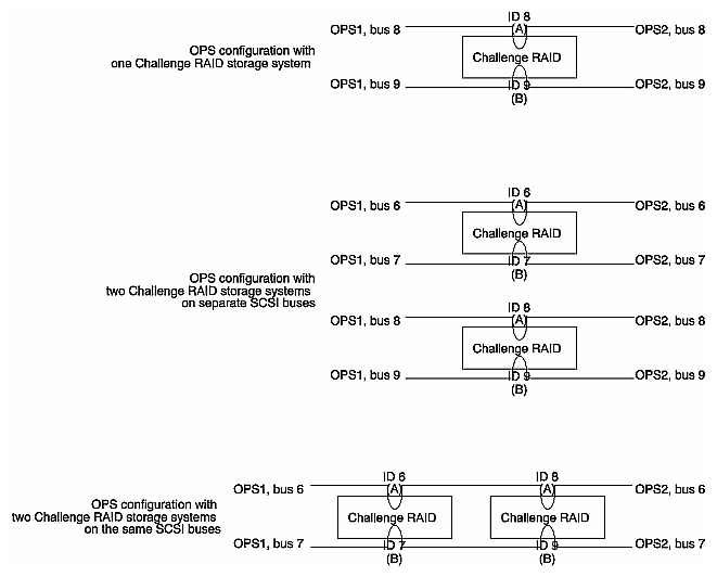
In an OPS configuration, each SCSI bus runs from a controller on one Challenge server through a vault or Challenge RAID to the second OPS host. For clarity, connect the controllers with the same numbers on a bus; for example, connect cable SCSI controller 2 on the first OPS host (OPS1) to SCSI controller 2 on the second OPS host (OPS2). Figure 2-3 diagrams a typical OPS configuration.
| Note: Make sure that controllers 2 and 5 and bus A on both optional vaults are differential. |
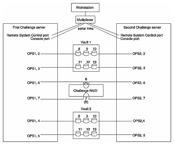
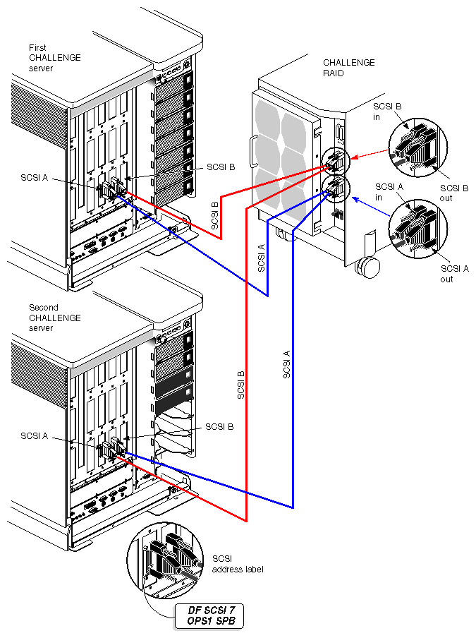
Figure 2-4 shows servers and vaults cabled for OPS.
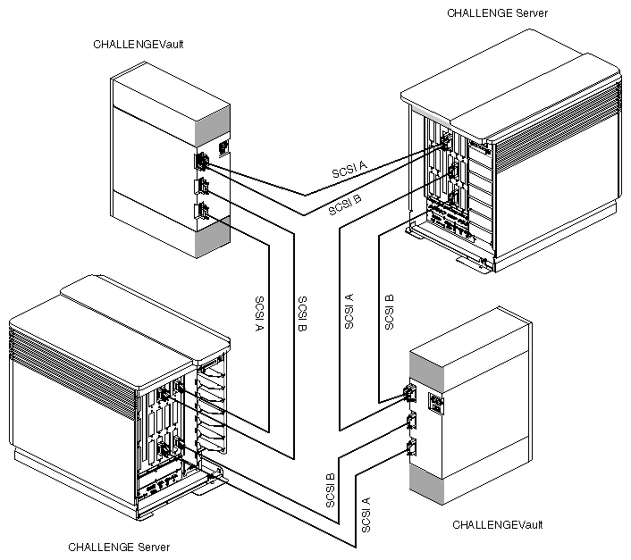
| Note: The IRISconsole is also linked to the Challenge RAID storage system; this link is not shown in Figure 2-4. |
The SCSI buses in the vaults and the Challenge RAID storage system are named A and B. The recommended procedure is to connect even-numbered SCSI buses to A and odd-numbered buses to B.
This section explains how to cable each SCSI bus on each vault to each OPS host. Follow these steps:
Have ready eight of the OPS host-vault cables. Use only these cables for this connection.
On blank labels from the label sheet, create labels OPS1, OPS2, Vault 1, and Vault 2. Attach the labels to the appropriate OPS hosts and vaults.
Power off both servers and vaults.
On the back of vault 1, insert one of the cables into the top SCSI channel A socket, as shown in Figure 2-5.
Label the cable end or connector; follow the scheme in Figure 2-3.
Connect the other end of this cable to an even-numbered SCSI bus port on the first OPS host (OPS1), as shown in Figure 2-5. Label the connector or cable end.
On the back of vault 1, insert a cable into the top SCSI channel B socket. Label the cable end.
Connect the other end of this cable to an odd-numbered SCSI bus port on the first OPS host (OPS1), as shown in Figure 2-6. Label the cable end or connector.
Insert a third cable into the lower SCSI channel A port on the back of vault 1. Label the cable end.
Connect the other end of this cable to the same even-numbered SCSI bus port on the second OPS host (OPS2) that you used on OPS1, as shown in Figure 2-7. Label the cable end.
Insert a fourth cable into the lower SCSI channel B port on the back of vault 1 and label it. Connect its other end to same odd-numbered SCSI bus port on the second OPS host (OPS2) that you used on OPS1. Label the cable end. Figure 2-7 shows all cables for the first vault installed.
Connect the four remaining cables to the second vault; follow the pattern in steps 4 through 11. Figure 2-4 earlier in this chapter shows this cabling.
If necessary, reset the SCSI bus selector settings on the front of each Challenge vault if they have been unset accidentally.
If one or more optional Digital Linear Tape drives (DLT) were ordered, install them in the server(s).
Power on the vaults. Power on the servers.
Do a dummy I/O to test each link. For example, in the numbering scheme used so far, to test SCSI bus 2, send data from OPS1 to disk 8 on SCSI bus 2 (dks2d8) and see if the disk light for disk 8 on the first vault lights up. Send data from OPS2 and see if the same LED is activated. Repeat this process for each bus.
Halt and power off each system.
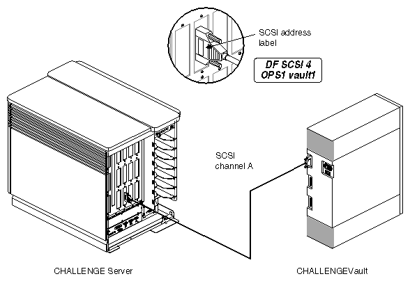
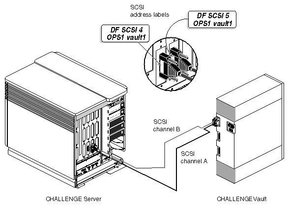

SCSI host address conflicts have caused the most problems in getting OPS up and running.
Setting the host SCSI IDs consists of these steps:
For the first OPS host, enter the command nvram. The last line of this command's output should contain the line
scsihostid=
This output means that the SCSI host ID for this OPS host is 0, the default.
Repeat step 2 in the second window for the second OPS host. The last line of the output should be scsihostid=2, meaning that the SCSI host ID for the second OPS host is 2.
If the second OPS host's SCSI host ID is not 2 (probably the case), follow these steps:
Reboot and start the System Maintenance menu; choose item 5, the Command Monitor.
In the Command Monitor, set the SCSI ID for this system:
setenv scsihostid 2

Caution: No SCSI device on any bus on any server should have SCSI ID 2. To verify that the SCSI ID was set, enter
printenv
The output should include the line scsihostid=2.
Exit the System Maintenance menu and restart the system.
Enter the command hinv; see Section 2.1, "Setting Up the Component Systems," for a sample output.
Enter the command hinv for the second server. Compare the output for each server.
Have the following manuals at hand:
FDDIXpress Release Notes
FDDIXpress Administration Guide (document number 007-0813-040)
FDDIXpress Mezzanine Board for CHALLENGE and Onyx Installation Instructions (108-0116-001)
To install the FDDI boards in the servers, follow these steps:
Check the contents of the FDDI board shipment, as explained in Chapter 1 of the FDDIXpress Mezzanine Board Installation Instructions.
Use the versions command to see if the system into which you are installing the FDDIXPress™ mezzanine board is already running FDDIXPress software. If FDDIXPress is not installed, install it following the instructions in the FDDIXpress Release Notes.
Install the FDDIXpress board following instructions in Sections 2.1 and 2.2 in Chapter 2 (Challenge L) or Sections 3.1 and 3.2 in Chapter 3 (Challenge XL) of the FDDIXpress Mezzanine Board for CHALLENGE and Onyx Installation Instructions.
Cable the connections and complete the installation as explained in Chapter 4 of the FDDIXpress Mezzanine Board for CHALLENGE and Onyx Installation Instructions.
Edit /etc/config/netif.options to include network addresses, for example:
 #  To override the name and/or address of the first gateway interface,
 #  change the value part and remove the leading : character.

 : if2name=ipg0
 : if2addr=dlm-$HOSTNAME

 #  If this host has more than 2 interfaces, you must define values for
 #  if3name (and if4name if appropriate). Change if3addr (and if4addr) to
 #  the appropriate names in /etc/hosts if your site has different naming
 #  conventions.

 if3name=
 if3addr=gate2-$HOSTNAME

 if4name=
 if4addr=gate3-$HOSTNAME
Edit /etc/hosts to include IP numbers for OPS1 and OPS2. Use test numbers that are not in use on the customer's network. For example:
 127.0.0.1       localhost
 #
 # This network number, '192.0.2' is the officially blessed 'test' network.
 #      It should be changed immediately to your own official network number.

 # start of well known machines--do not remove this line
 # main ethernet network
 192.26.79.38    ops1
 192.26.79.39    ops2
 # for DLM FDDI connection only
 192.0.2.200     dlm-ops1
 192.0.2.201     dlm-ops2
 #
Finish configuring the new FDDI station, as explained in Chapter 2 of the FDDIXpress Administration Guide. If you are familiar with the procedures, follow the section "Quick and Easy Configuration Instructions" in that chapter.
Verify the FDDI connection, as explained in Chapter 2 of the FDDIXpress Administration Guide.
The SCSI ports on the Challenge RAID storage system are cabled to both Challenge servers; consult the diagram in Figure 2-3.
Table 2-1 charts SCSI ID switch settings for the Challenge RAID storage system. Note that the settings do not conform to frequently used numbering schemes.
Table 2-1. Challenge RAID SCSI ID Switch Settings
SCSI ID Number | Switch Number |
|
|
| Comment |
|---|---|---|---|---|---|
| ID 0 | ID 1 | ID 2 | ID 3 |
|
1 | Off | On | On | On |
|
2 | On | Off | On | On | Do not use |
3 | Off | Off | On | On |
|
4 | On | On | Off | On |
|
5 | Off | On | Off | On |
|
6 | On | Off | Off | On | Shown in Figure 2-3 as A |
7 | Off | Off | Off | On | Shown in Figure 2-3 as B |
8 | On | On | On | Off |
|
9 | Off | On | On | Off |
|
10 | On | Off | On | Off |
|
11 | Off | Off | On | Off |
|
12 | On | On | Off | Off |
|
13 | Off | On | Off | Off |
|
14 | On | Off | Off | Off |
|
15 | Off | Off | Off | Off |
|
To cable the Challenge RAID storage system to the Challenge servers, follow these steps:
Have ready the two remaining SCSI cables and the two 20-foot SCSI cables included in the Challenge RAID shipment (p/n 9290111).
Using blank labels from a label sheet, create two labels that say DF SCSI n and two labels that say DF SCSI N, where n and N are the numbers of two remaining SCSI controllers on the servers (in the example in Figure 2-3, these are 6 and 7).
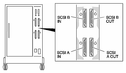
Attach the two even-numbered labels below the SCSI A in symbol and SCSI A out symbol silk-screens on the Challenge RAID storage system. Attach the two odd-numbered labels below the SCSI B in symbol and SCSI B out symbol on the Challenge RAID storage system. Figure 2-8 shows the Challenge RAID SCSI ports.
On the back of the Challenge RAID storage system, attach a SCSI cable to the Challenge RAID SCSI A in port. Connect the SCSI cable to the SCSI A in connector as shown in Figure 2-9, making sure the connector is inserted securely.
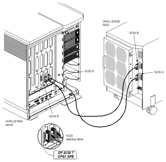
Connect the other end of this cable to the even-numbered SCSI bus on OPS1, as shown in Figure 2-10.
Continue cabling as diagrammed in Figure 2-11.
Figure 2-12 shows a typical hookup for an OPS configuration with one Challenge RAID storage system.
To cable the Indy, Indigo, or Indigo2 workstation to the Challenge servers, follow these steps:
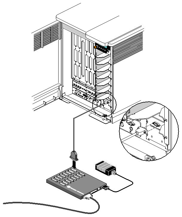
Have ready the contents of the IRISconsole multiplexer kit and the pair of cables included in the cable kit, so that you have four 2-ft DB25-DB9 serial cables (p/n018-0527-001).
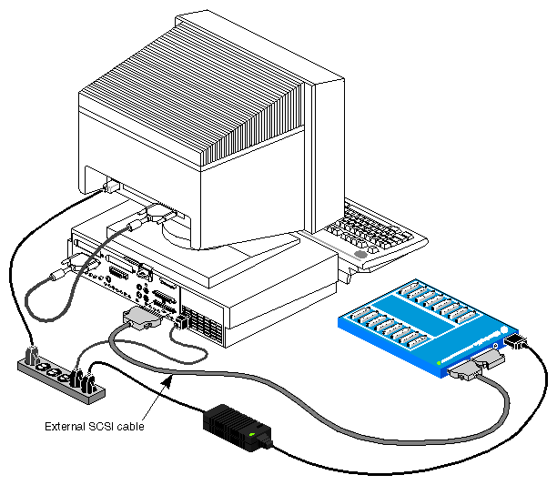
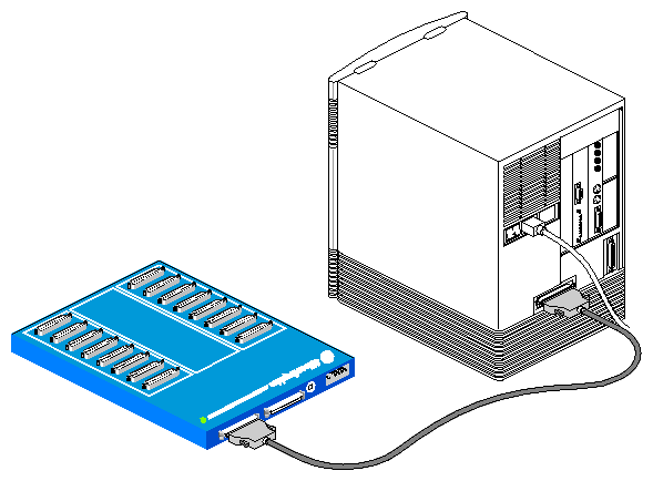
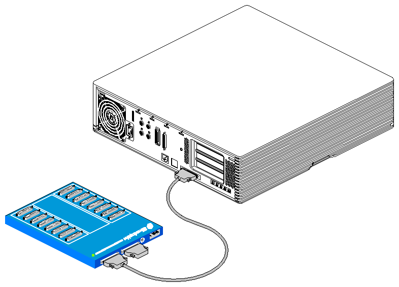
Connect one end of the SCSI cable (018-0526-001) included in the multiplexer kit to the workstation's SCSI port, as shown in Figure 2-13, Figure 2-14, and Figure 2-15.
Attach the other end of the cable to the leftmost socket on the back of the multiplexer, as shown in Figure 2-13.
If the customer has purchased two multiplexers, attach the cable of the second multiplexer to the middle socket on the first multiplexer.
Cable the power supply to the rightmost port on the multiplexer, as shown in Figure 2-13.
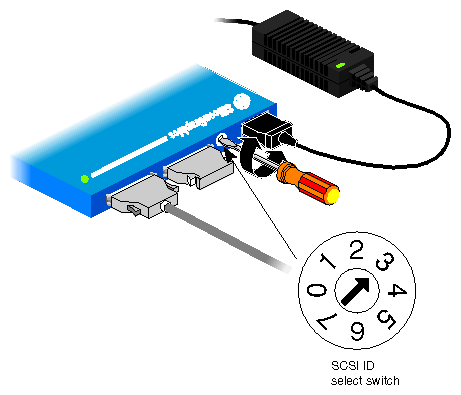
Select an appropriate SCSI ID number by inserting a small screwdriver or other tool and rotating the arrow, as shown in Figure 2-16. Using SCSI ID 7 on early models of the multiplexer causes the power indication LED to blink. Select another ID and the LED glows steadily with no blink.
Note: The system disk in the Indigo workstation is always SCSI target ID 1 (on the Indy and Indigo2, ID 1 is the default). Never select SCSI ID 1 for a multiplexer.
If the multiplexer is the last SCSI device on the workstation's standard external SCSI port, terminate it properly by attaching the external SCSI terminator included in the multiplexer shipment. See Figure 2-13.
Reboot the workstation.
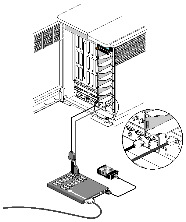
Attach a 25-pin end of a serial cable to serial port 1 (or another port, as the customer wishes) on the top of the multiplexer.
Connect the 9-pin connector from serial port 1 on the multiplexer to the connector labeled System Console tty_1 on the I/O panel of the first OPS host (OPS1), as shown in Figure 2-17.
Attach a 25-pin end of a serial cable to serial port 2 (or another port, as the customer wishes) on the top of the multiplexer. Connect the other end of this cable to the Remote Sys Control SSE Use Only connector, which is to the right of the I/O panel on the first OPS host, as shown in Figure 2-18.
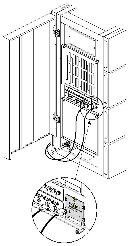
Figure 2-19 shows cabling for a Challenge XL.
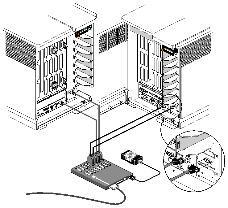
Repeat steps 1 through 3 for the second OPS host: attach serial cables from ports 3 and 4 on the multiplexer to the OPS2's System Console tty_1 and Remote Sys Control SSE Use Only ports, respectively.
Figure 2-20 diagrams IRISconsole multiplexer cables.
Note: Do not use the 8-pin powered serial connector in systems that have the IRISconsole multiplexer installed.
To power on the component systems, follow these steps:
Make sure that the Challenge RAID power switch is off.
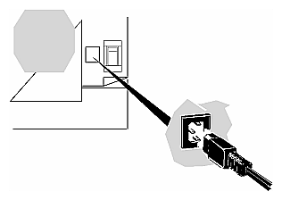
Connect the power cord to the storage system. Plug the other end of the power cord into an AC power outlet. See Figure 2-21.
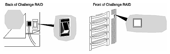
Turn on the storage system's power. The green power light on the front of the Challenge RAID storage system comes on, and the fans rotate. See Figure 2-22.
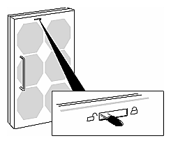
If the busy light on none of the drive modules lights up, make sure that the power for each storage-control processor is enabled. Move the fan module's latch to the UNLOCK position, as indicated in Figure 2-23.
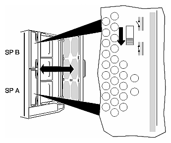
Swing open the fan module and move the power switch for each disabled storage-control processor to the enable position, as shown in Figure 2-24.
Swing the fan module closed, and then move the latch to the LOCK position.
Caution: Do not leave the fan module open for more than two minutes at any time. The Challenge RAID storage system shuts down if the fan module is disabled for more than two minutes. If necessary, connect the power cables and power on the OPS hosts, the Challenge RAID, the workstation, and the multiplexer.
To test the OPS installation, run hinv on a server. Figure 2-25 shows a sample output.