This chapter describes how to install the Multi-Channel Option (MCO) in a VME slot in the following IRIS chassis:
deskside: POWER Series, Crimson (Diehard II), and Onyx (Eveready)
rack: POWER Series (Predator), SkyWriter, and Onyx (Terminator)
The installation procedure is divided into the following steps:
preparing the chassis
installing the EF5s and attaching 24W7 cables
installing and cabling the sync and genlock panels
jumpering the Onyx backplane or midplane
changing the physical VME address on the board
attaching microstrip cables to the paddleboards
attaching the 24W7 cables and closing the chassis
cabling the VIDI/O BOX™ from Truevision® for use with MCO
restarting the system and installing the Multi-Channel Option software
For MCO in an Onyx, IRIX release 5.0.1 or later is required. If the Onyx is running 5.0, upgrade to 5.0.1 or later before proceeding.
For POWER Series or Crimson, 4.0.5H or later is required. If the system is running an earlier version, upgrade it before proceeding.
The system should have been upgraded to latest versions of hardware; for example, the F chips on the IO4 board must be version 2 for the Multi-Channel Option to function in the system.
Other Silicon Graphics manuals contain instructions for exchanging circuit boards. Make sure you have the appropriate one(s):
Single Tower Maintenance Manual (108-7002-xxx): Crimson and POWER Series systems
CHALLENGE™/Onyx™ L Deskside Installation Instructions (108-7039-xxx)
CHALLENGE™/Onyx™ XL Rackmount Installation Instructions (108-7042-xxx)
CHALLENGE and Onyx Retrofit Instructions (domestic version: 802-0107-002; international version: 802-0106-002)
Challenge/Onyx Rackmount Third Cardcage (CC3) Upgrade Instructions (release note, 802-0105-xxx): setting up cardcage 3 for Onyx rackmount
SkyWriter Installation Instructions (108-7011-xxx)
Make sure you have other pertinent release notes and Field Information Bulletins as well.
You need a flat-blade screwdriver and a Phillips screwdriver to install the Multi-Channel Option. To run diagnostics, use the IDE diagnostics CD for IRIX 5.2 (812-0119-005), 5.1 (812-0121-003), IRIX 5.0.1 (812-0121-002), or IRIX 4.0.5H (806-0007-009) as explained in Chapter 6, "Using Multi-Channel Option Diagnostics," in this document.
You will need jumpers for the backplane or midplane of the machine if you are installing the MCO in an Onyx:
Onyx deskside chassis and cardcage 2 (CC2) of an Onyx rackmount chassis: up to 20 jumpers (p/n 9090003)
cardcage 3 (CC3) of an Onyx rackmount chassis: up to four interrupt boards (p/n 030-0516-xxx)
To prepare the chassis for installing the option, follow these steps:
 | Caution: Board components are extremely sensitive to electrostatic discharge. Use proper antistatic procedures while handling the board. |
Make sure all users are off the target system. To check the revision level of the RM board(s) before you shut down the system, type as root
In the result, look for a line such as
2 RM boards (rev. 00102/00102)
To work properly with MCO, the last digit of each RM board reported must be a number other than zero. If the system is running a field-sequential format, the digit must be greater than one.
Shut down the system; open the chassis, removing the rear outer panel if necessary.
Open the rear metal panel to expose the slots.
Check the revision level of the VCAM in the system. Not many of these exist. Determine the revision level by inspecting O0B0 and M9C0:
no rework at O0B0 and no rework at M9C0: 030-0500-003
rework at O0B0 and no rework at M9C0: 030-0500-004
rework at O0B0 and rework at M9C0: 030-0500-005
If the VCAM is revision level 030-0500-004, swap it for another revision level.
Check the revision level of the RM boards in the system. Each board must have a number other than zero (or one) as its last digit, or have one of these part numbers:
030-0235-004 (00101)
030-0337-001 or 030-0338-001 (00102) for field-sequential formats
030-0359-001 or 030-0360-001 (00112) for field-sequential formats
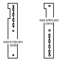
In Crimson or POWER Series deskside systems with dual processor boards (four processors), the existing plate assembly for the second processor board is situated on the blank plate or sheet metal panel (p/n 040-0159-001) so that there is no room to attach the PB3 paddleboard to the MCO board. The replacement panel (p/n 040-0765-001) included in the MCO shipment situates the plate assembly on its lower half, allowing room for the PB3. Figure 2-1 depicts these panels.
If you are installing the Multi-Channel Option in a Crimson or POWER Series deskside system with dual processors and the old sheet metal panel (p/n 040-0159-001), you must replace the panel. Follow these steps:
Unscrew the plate assembly (p/n 013-0861-001) from the sheet metal panel. Detach the flat ribbon cable (018-0136-001) if necessary.
Unscrew the old metal panel (p/n 040-0159-001) from the I/O door.
Install the new panel (p/n 040-0765-001) shipped with MCO into the I/O door over the same I/O slots as the one you removed.
Screw the plate assembly onto the new sheet metal panel. Reattach the flat ribbon cable if necessary.
Plan where to install the MCO board, the EF5 panels, and the cables:
VME slot required: To allow room for internal cables, the option should go into VMME slot 3 in the Crimson or POWER Series, the VME slot closest to the DG2 board in the Onyx deskside, and any available VME slot in the SkyWriter and Onyx rackmount.
If the appropriate slot is occupied by an existing option, move it to free the slot. If slot 1, slot 2, or both are unoccupied, you must jumper the backplane, as explained in this chapter.
Space for paddleboards: The paddleboards that you will attach to the MCO and DG2 boards extend into the space between the board slots and the I/O door. To avoid interference from the paddleboards and their cables, you may need to move existing options.

Note: For a Crimson chassis, clearance between the edges of the paddleboards and the I/O door, when closed, is only 1/10 inch. Space for cables: Care must be taken to avoid crimping any cables, particularly the sensitive microstrip cables that join the two paddleboards.
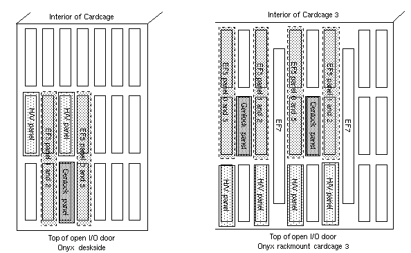
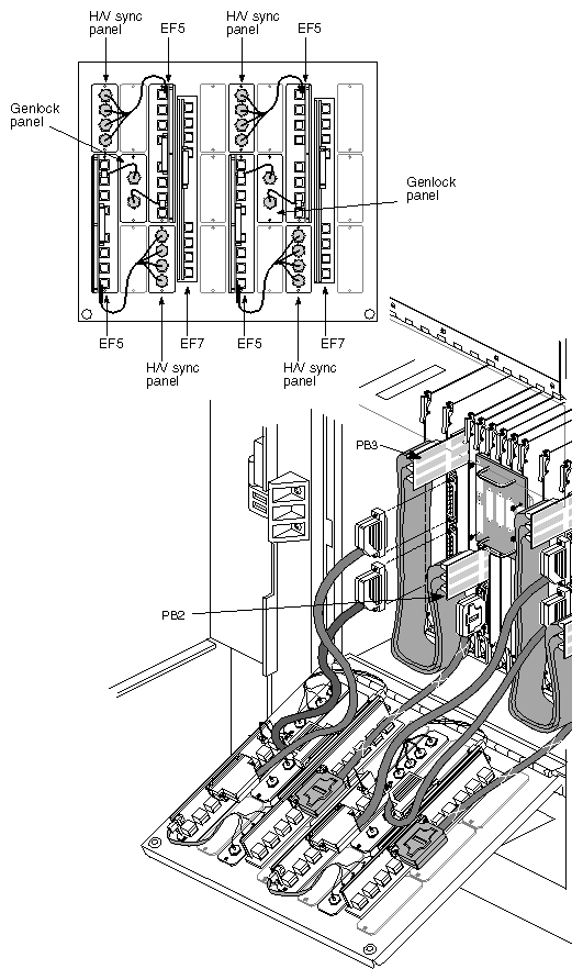
EF5 panel placement: Each EF5 occupies two adjacent (lengthwise) slots on the I/O door. The EF5s for channels 0 and 5 and for channels 1 and 2 must occupy parallel but alternate slots, with the genlock panel in a slot between them.
Note: In an Onyx deskside system, the EF5 panels must occupy the leftmost slots on the I/O door to allow room for the PB3. In cardcage 3 of an Onyx rackmount, the two EF5 panels for channels 1 and 2 must be installed upside down. Figure 2-2 diagrams this placement.
Typically, the Multi-Channel Option panels are installed in the upper slots because of the length of the associated cables.
H/V sync panels: If the customer is using composite sync- or sync-on-green type monitors, the H/V sync panels might not be required. Because the Multi-Channel Option requires several slots, ask the customer if H/V panels should be installed.
Remove the appropriate number of slot covers. For example:
For a deskside system and for a rackmount system using four channels, remove five to seven slot covers, depending on whether the customer is using H/V sync.
For a rackmount system using six channels, remove seven to ten slot covers, depending on whether the customer is using the H/V sync panels.
Note: Reserve the screws for use with the Multi-Channel Option.
Illustrations of complete option installations appear later in this chapter:
Crimson chassis: Figure 2-20
POWER Series rackmount chassis: Figure 2-21
SkyWriter chassis: Figure 2-22
Onyx deskside chassis: Figure 2-23
Onyx rackmount chassis: Figure 2-24 and Figure 2-25
The three EF5 panels are not interchangeable. Each of the three EF5 panels outputs to two different channels and has a different silkscreen:
EF5 for channels 0 and 5 (p/n 013-0557-001 for Crimson and POWER Series, 013-0835-001 for Onyx)
EF5 for channels 1 and 2 (p/n 013-0621-001 for Crimson and POWER Series, 013-0833-001 for Onyx)
if the customer is using the six-channel option: EF5 for channels 3 and 4 (p/n 013-0622-001 for Crimson and POWER Series, 013-0834-001 for Onyx)
To install the EF5 panels, follow these steps:
Select the two slots (adjacent lengthwise) for the EF5 0 and 5 panel. These slots are the two leftmost slots from which you have removed slot panels. Refer to Figure 2-2.
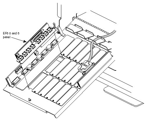
Orient the EF5 panel over the slots, with the top of the panel aligned with the top of the I/O door, as shown in Figure 2-3.
Screw EF5 panel for channels 0 and 5 into place.
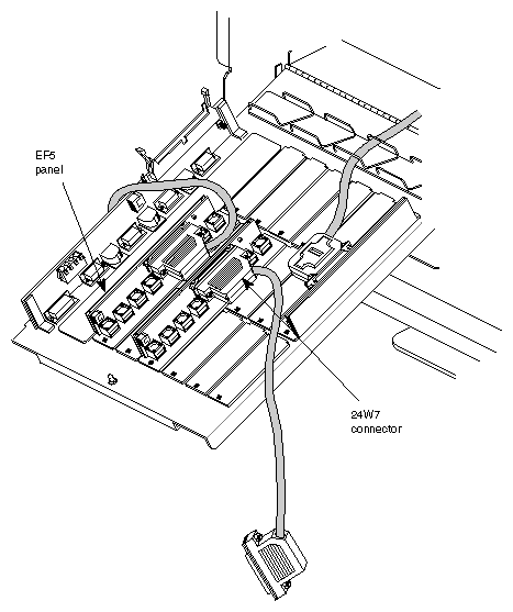
Attach one end of a 24W7 cable to the connector on the EF5 panel for channels 0 and 5. The cable should exit toward the bottom of the board, as shown in Figure 2-4. Screw it in.
Skipping a pair of slots, orient the EF5 1 and 2 panel over the next pair of slots (adjacent lengthwise). Align the top of the board with the top of the I/O door.
Note: If you are installing the MCO in cardcage 3 of an Onyx rackmount chassis, you must orient the EF5 panel for channels 1 and 2 upside down. See Figure 2-2. Screw the EF5 panel for channels 1 and 2 into place.
Attach one end of a second 24W7 cable to the connector on the EF5 panel for channels 1 and 2. The cable should exit toward the bottom of the I/O door. Screw it in.
Note: In the case of the upside-down EF5 panel(s) for channels 1 and 2 in Onyx rackmount CC3, the cable exits toward the top of the I/O door. If the customer is using channels 3 and 4, install that EF5; attach one end of the third 24W7 cable to it as explained earlier. Even if the customer is not using H/V sync panels, you must skip a pair of slots between the EF5 for channels 1 and 2 and the EF5 for channels 3 and 4 to allow room for the video connectors.
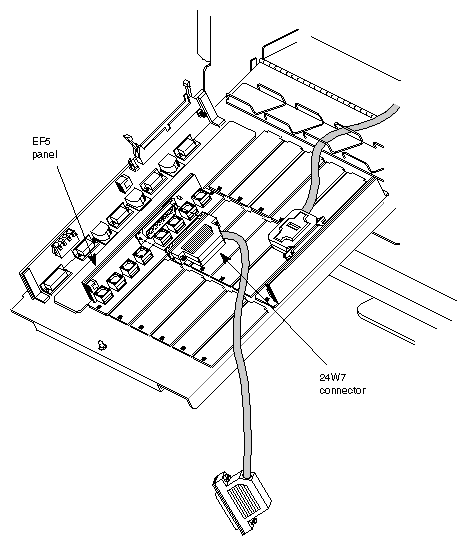
Figure 2-5 shows two EF5 panels installed, with 24W7 cables attached.
In a multipipe system, repeat the process for each set of EF5 panels.
After you have installed the EF5 panels, install the genlock and H/V sync panels over the slots between. You'll install
and, if the customer is using them
H/V sync panel for channels 0 and 5 (p/n 013-0659-001 for Crimson and POWER Series, 013-0838-001 for Onyx)
H/V sync panel for channels 1 and 2 (p/n 013-0658-001 for Crimson and POWER Series, 013-0836-001 for Onyx)
H/V sync panel for channels 3 and 4 (p/n 013-0660-001 for Crimson and POWER Series, 013-0837-001 for Onyx)
To install and cable the genlock and sync panels, follow these steps:
Position the genlock panel over the middle slot between the EF5 0 and 5 panel and the EF5 1 and 2 panel. Figure 2-6 diagrams this placement on the inside and outside of the I/O door. For an Onyx rackmount chassis, consult Figure 2-2.
Screw in the genlock panel.
Cable the genlock panel for loopthrough:
push the coax cable attached to GEN IN on the genlock panel onto the J10 connector on the EF5 0 and 5 panel
push the coax cable attached to GEN OUT on the genlock panel onto the J10 connector on the EF5 1 and 2 panel
Figure 2-7 shows this cabling.
In a multipipe system, repeat this step for each set of I/O panels.
If the customer is using H/V sync, position the H/V sync panel for channels 0 and 5 next to the EF5 panel for channels 0 and 5, over the slot adjacent (lengthwise) to the one you used for the genlock panel. Align the top of the H/V sync panel with the top of the I/O door and screw it in. See Figure 2-8.
Position the H/V sync panel for channels 1 and 2 next to the EF5 for channels 1 and 2. Install the panel.
If the customer is using six channels, position the H/V sync panel for channels 3 and 4 next to the EF5 for channels 3 and 4. Install the panel.
Cable the H/V sync panel for channels 0 and 5 to the EF5 0 and 5 panel: attach the black plastic 4 x 2 connector to the EF5's J11 connector, as shown in Figure 2-9. The connectors are keyed.
If necessary, coil the cables and tuck them out of the way against the raised sides of the EF5s.
Repeat the process for the remaining H/V sync panel(s), cabling each H/V sync panel to the appropriate EF5.
Figure 2-10 shows all panels installed in a Crimson chassis.
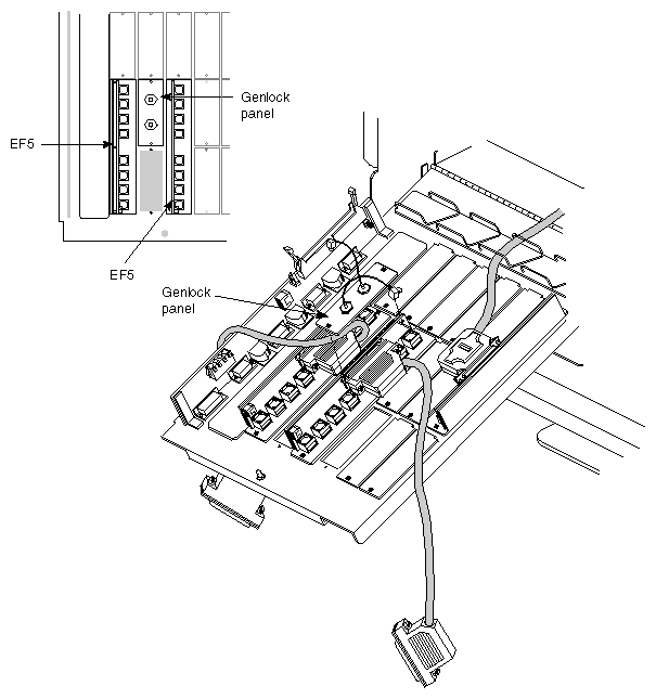
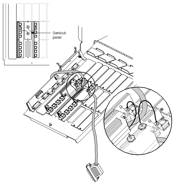
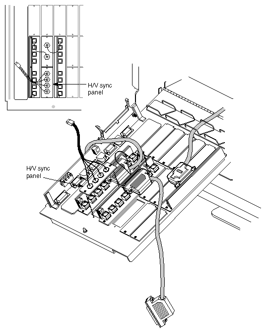
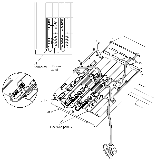
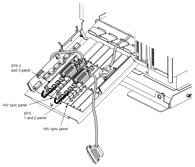
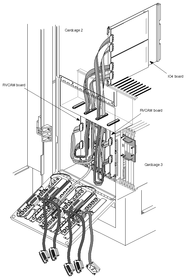
Figure 2-11 shows all panels installed in an Onyx rackmount chassis.
Changing the default VME address for the Multi-Channel Option is required when
the board's address space conflicts with another A24 VME peripheral installed in the same system
you are installing a second MCO into the same VME bus to split the graphics output from pipe 1 of a dual-head MP bus-based SkyWriter system (RealityEngine graphics)
| Note: If you are installing an MCO in a Crimson or POWER Series workstation (not SkyWriter) under 4.0.5H, it must be on graphics pipe 0. |
Changing the MCO board's address requires resetting DIP switches, as explained in this section, and, for IRIX versions before 5.2, making software changes, as explained in Chapter 4, "Setting VME Addresses."
The VME address is factory set to 0x00800000, corresponding to graphics pipe 0. The DIP switch on the far right is set; all others are unset. Default physical VME addresses are listed in Table 2-1.
Table 2-1. Default VME Addresses
Pipe | Name in /usr/sysgen/master.d/mem | Physical Starting Address and Range |
|---|---|---|
VIDEO_VS2_A24_NP_BASE_PIPE0 | 0x00800000 - 0x0080ffff | |
VIDEO_VS2_A24_NP_BASE_PIPE1 | 0x00810000 - 0x0081ffff |
DIP switch settings for the physical VME addresses are diagrammed in Figure 2-12.
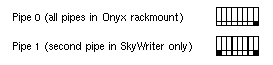
To change the VME address on the second MCO board in an MP bus-based system, set the DIP switches for pipe 1 as follows:
set leftmost switch
leave rightmost switch set
all others are unset
| Note: For multipipe in an Onyx rackmount chassis, leave all (one, two, or three) VS2 boards set to the default DIP switch settings. Use an adapter number when configuring the DG2 EEPROM with the address for each board, as explained in Chapter 4, "Setting VME Addresses." You must use the separate VME buses that accompany each graphics pipe in the Onyx rackmount system; otherwise, the MCO microstrip cabling will not be able to reach the DG2 board. |
If the customer wants to use addresses other than the defaults, follow these guidelines:
The MCO board requires an address space of 0x10000 (65536) bytes.
For release 5.2 and later, you must choose an address from the following:
POWER Series, pipe 0: 0x00800000, 0x00900000, 0x0a00000, 0x0b00000, 0x0c00000, 0x0d00000, 0x0e00000, 0x0f00000
POWER Series, pipe 1: 0x0810000, 0x0910000,0x0a10000, 0x0b10000, 0x0c10000, 0x0d10000, 0x0e10000, 0x0f10000
Onyx, any pipe: any address listed at the two subbullets above
For release 5.1 and earlier, the valid range of physical starting addresses for the MCO board is the upper 8 MB of VME A24:
0x00800000 - 0x00ff0000
Addresses should be on 64-KB boundaries (0x10000, 65536) for proper alignment.
| Note: You must also reconfigure the DG2 EEPROM and (for MP bus-based systems) the mem file. Instructions are in Chapter 4, "Setting VME Addresses." |
If you are installing any VME board in an Onyx deskside or rackmount chassis and are skipping slots, you must jumper the backplane or midplane. Because the MCO board must be installed as close as possible to the DG2 board in an Onyx, skipping slots might result. If the backplane or midplane is not jumpered, the MCO will not show up in the hinv output.
The procedure varies, depending on whether you are installing MCO in
an Onyx deskside system
cardcage 2 of an Onyx rackmount system
cardcage 3 of an Onyx rackmount system
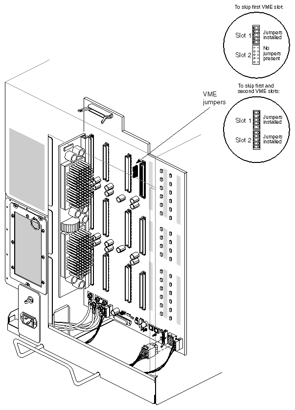
Insert jumpers (p/n 9090003) into the jumper banks that correspond to the VME slot numbers you are skipping. For example, if you are skipping the first VME slot, insert jumpers into jumper bank 1. To jumper a bank, connect all five pairs of posts with jumpers.
Follow these guidelines:
If you are skipping the first VME slot (that is, slot 5 in an Onyx or slot 7 in a CHALLENGE™ system) to use the next VME slot, place five jumpers in the jumper bank designated as slot 1 (see Figure 2-13).
If you are skipping the first two VME slots to use the third VME slot, place jumpers in banks 1 and 2.
If boards occupy VME slots 1 and 3, and slot 2 is vacant, place jumpers in bank 2.
Figure 2-13 shows placement of the jumpers.
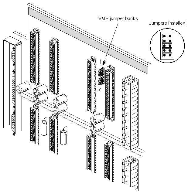
Insert jumpers (p/n 9090003) into the jumper banks that correspond to the VME slot numbers you are skipping. Jumper the VME slots only if you are leaving gaps between the VCAM in slot 16 and the MCO board or any other VME boards, or if you are skipping slots between VME boards.
Corresponding to each slot is a bank of five jumpers, as shown in Table 2-2.
The jumper banks are located on the cardcage 1 side of the midplane, between the power bus slots, as shown in Figure 2-14.
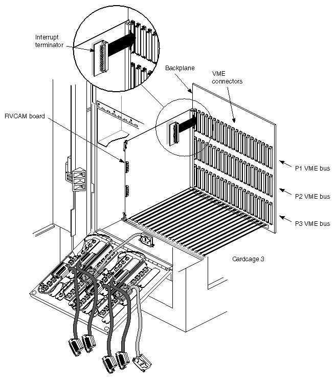
Typically, between each remote VCAM and each graphics head in cardcage 3 are three VME slots. The MCO should be put in the rightmost or middle slot of the three in each case.
If no other VME cards occupy the slot(s) to the left of the MCO board, you must attach an interrupt terminator (interrupt board) (p/n 030-0516-00x) to the top connector (P1 VME bus connector) for each slot on the backplane, as shown in Figure 2-15. Interrupt boards are required because there are no jumper banks for slots on the cardcage 3 backplane.
In this step you attach the paddleboards to the MCO board (labeled VS2) and DG2 board, attach nylon spacers (standoffs) to each of the two paddleboards, and insert the MCO board into the chassis.
The paddleboards must be attached as follows:
The names of the paddleboards are silkscreened onto the component side.
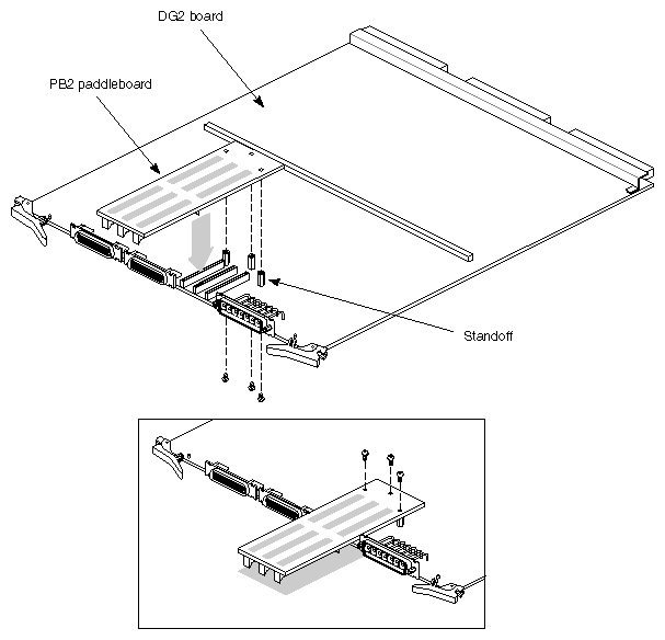
To attach the PB2 paddleboard to the DG2, follow these steps:
Detach the front plane so that the DG2 board is accessible. Detach the 24W7 cable connector from the EF7; leave the small cable (stereo sync) attached to the DG2 board.
Remove the DG2 board from the chassis and lay it on a nonstatic surface.
Install three nylon spacers (p/n 7430100) into the connector side of the PB2. Make sure you have the PB2 paddleboard (p/n 030-0328-001), not the PB3 paddleboard.
Making sure the two cables for stereo and swap ready remain connected to the two-pin connectors on the DG2, mate the three connectors (J1, J2, and J3) on the PB2 paddleboard (p/n 030-0328-002) to the P6, P7, and P8 connectors on the DG2 board.
Supporting the DG2 board from the other side, carefully push the PB2 paddleboard onto the connectors. Be careful not to bend the DG2 board.
Caution: Be extremely careful not to bend or smash the pins in the paddleboard connectors; they are very fragile. If a pin gets bent, vertical stripes appear on all MCO channels. These pins cannot be reliably repaired. If they are damaged, replace the entire paddleboard. From the other side of the DG2 board, screw three nylon screws (p/n 93-00407) into the spacers.
Figure 2-16 shows installation of the paddleboard onto the DG2 board.
Reinsert the DG2 board into its slot. Reattach the front plane and 24W7 cable.
Note: If you need to replace the DG2 board for any reason, you must reset the default address for the MCO board, which is stored in the DG2's EEPROM. Instructions are in Chapter 4, "Setting VME Addresses."
To attach the PB3 paddleboard to the MCO board and install the board, follow these steps:
Install three nylon spacers (p/n 7430100) into the connector side of the PB3 paddleboard (p/n 030-0352-001) as you did for the PB2.
Mate the three connectors (J1, J2, and J3) on the PB3 paddleboard to the three connectors (J1, J2, and J3) on the MCO board.
Supporting the MCO board from the other side, ease the PB3 paddleboard onto the connector. Be careful not to bend the MCO board.
Caution: Be extremely careful not to bend or smash the pins in the paddleboard connectors, as they are very fragile. If a pin gets bent, vertical stripes appear on all MCO channels. These pins cannot be reliably repaired. If they are damaged, replace the entire paddleboard. From the other side of the MCO board, screw three nylon screws (p/n 93-00407) into the spacers.
Grasp the Multi-Channel Option board so that your hands are on the ejector tabs and the component side of the board faces right.
The MCO board goes in:
Caution: Check for ribbon cables to the immediate left of the slot you have selected. Hold any cables flat against their respective boards while inserting the Multi-Channel Option board to prevent them from being chafed by the Multi-Channel Option board components. Insert the MCO board all the way into the cardcage slot. Angle the board's plastic ejectors outward so that the U-shaped grooves of the ejectors fit into the upper and lower metal frames of the system.
Push the upper and lower ejector tabs toward the center of the board's lower edge until both are vertical. You should hear and feel the board seat into the connectors on the backplane.
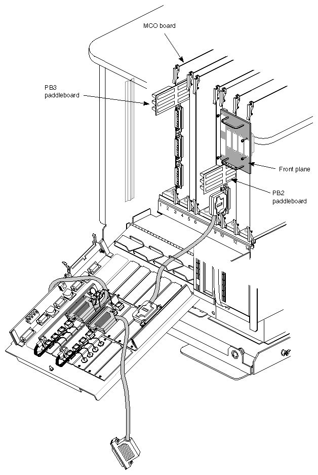
Figure 2-17 shows both boards in place, with paddleboards attached.
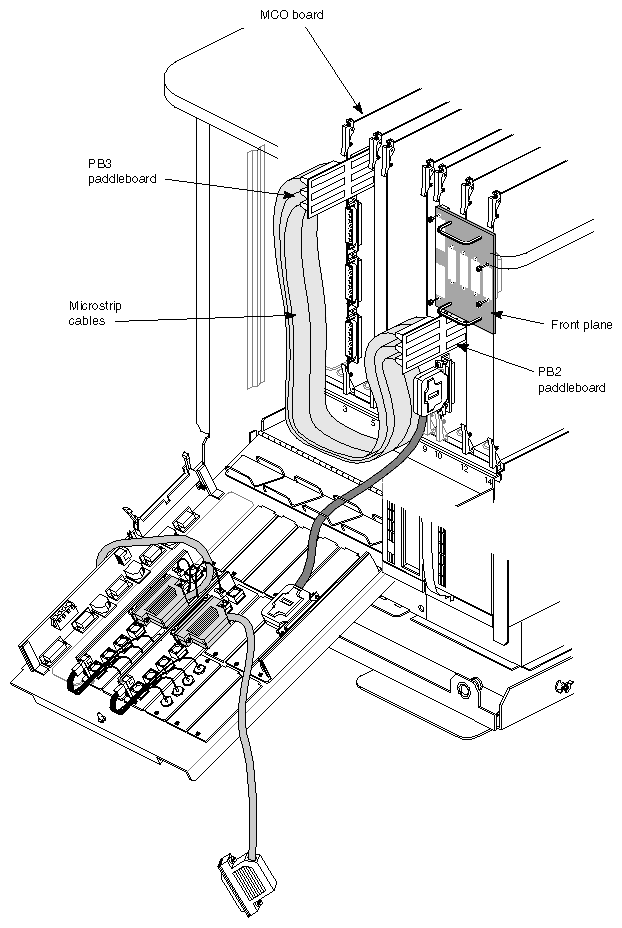
The three sets of microstrip cables that connect the two paddleboards are shipped in rolls protected by plastic.
| Note: The cables, which are taped in the middle to minimize tangling, are very fragile. Exercise care in handling them. |
The cables are attached as follows, so that they nest and lie flat:
Follow these steps:
Holding down the metal strip connector latches on each side of a connector of a microstrip cable, insert the connector onto the top socket (J4) on the PB3 paddleboard. The connector is keyed. Release the connector latches to secure the cable in place.
Holding down the connector latches, insert the connector on the other end of the microstrip cable onto the bottom socket (J4) on the PB2 paddleboard; release the connector latches to secure the cable in place.
Attach the middle microstrip cable: plug a connector into the middle socket (J5) on the PB3 board and insert the other connector onto the middle socket (J5) on the PB2 board.
Attach the last microstrip cable: plug a connector into the bottom socket (J6) on the PB3 board and insert the other connector onto the top socket (J6) on the PB2 board.
Note: For the best cable routing, feed each microstrip cable underneath all of the other cables in the cable trough so that the microstrip cables actually lie on the sheet metal. The cables can lie on the floor of the cardcage. Figure 2-18 shows the cables attached.
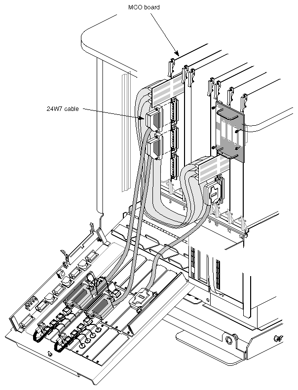
You have already installed one end of each 24W7 cable onto each EF5 panel in the system. To install the other ends of the 24W7 cables onto the MCO board, follow these steps:
Attach the connector of the 24W7 cable from the EF5 panel for channels 0 and 5 to the J4 connector (the top 24W7 connector) on the MCO board and screw it in. The cable must exit from the bottom of the connector.
Attach the connector of the 24W7 cable from the EF5 panel for channels 1 and 2 to the J5 connector (the middle 24W7 connector) on the MCO board and screw it in. The cable must exit from the bottom of the connector.
If the customer is using six channels, attach the connector of the 24W7 cable from the EF5 panel for channels 3 and 4 to the J6 connector (the bottom 24W7 connector) on the MCO board. The cable must exit from the bottom of the connector.
Note: The 24W7 cables must be connected to the J4 and J5 connectors on the MCO board to complete the genlock loopthrough path. If one or both cables are not so connected, genlock performance is not guaranteed. Carefully and gradually close the I/O door.
Caution: Exercise extreme care in closing the I/O door so that the paddleboards and cables are not damaged. This process may require repositioning cables and, in the worst cases, reinstalling panels and boards in different locations.
Figure 2-19 through Figure 2-25 show the 24W7 cables completely installed.
| Caution: If the specific connectors on the MCO board are not cabled to the specific EF5 panels detailed in these instructions, channel output is not guaranteed. |
Figure 2-20 shows all boards, cables, and panels installed in a Crimson chassis.
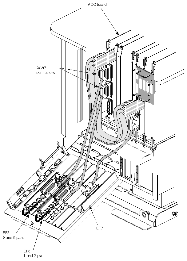
shows all boards, cables, and panels installed in a POWER Series chassis Figure 2-21.
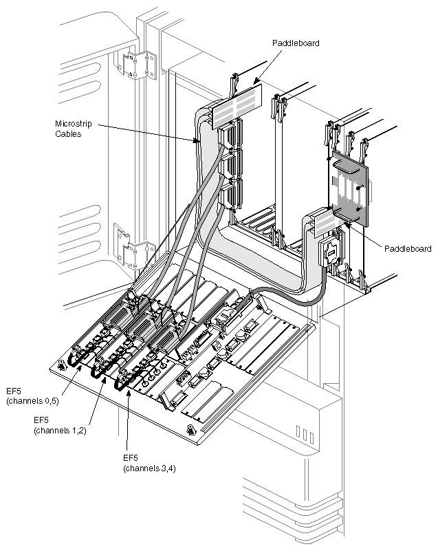
Figure 2-22 shows all boards, cables, and panels installed in a SkyWriter chassis.
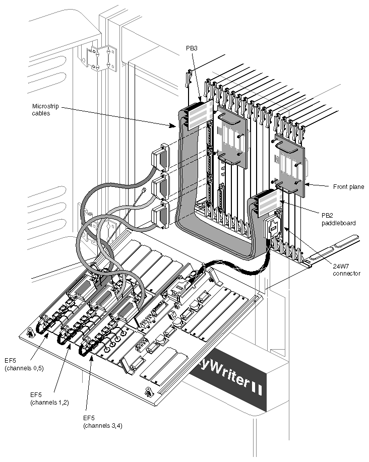
Figure 2-23 shows all boards, cables, and panels installed in an Onyx deskside chassis.
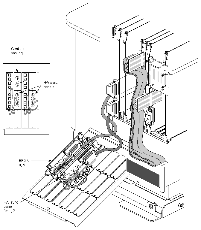
Figure 2-24 shows all boards, cables, and panels installed in cardcage 2 of an Onyx rackmount chassis.
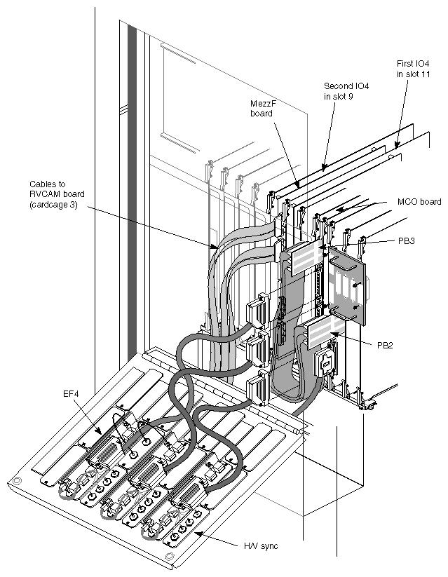
Figure 2-25 shows all boards, cables, and panels installed in cardcage 3 of an Onyx rackmount chassis.
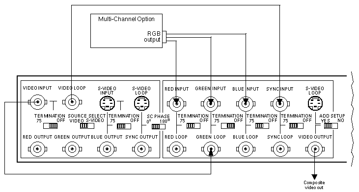
If the customer is using a VIDI/O BOX from Truevision to convert RGB output to NTSC output (one VIDI/O BOX is required for each output channel) using the n@640x486_30i video output format, you must cable the box for use with MCO. Follow these steps:
Daisy-chain the MCO green output (sync on green) to the encoder green input, the decoder video input, and the sync input.
Set the termination switch for the sync input to 75. Set the termination switches for the green input and video input to OFF.
Connect red and blue normally. Set the termination switches to 75. No connection to the MCO genlock is required.
Figure 2-26 diagrams these connections.
Load the Multi-Channel Option software from the CD included in the package. Installing the Multi-Channel Option software changes some of the IRIX system files, so backup is recommended.
| Caution: Do not install 4.0.5H or 5.0.1 MCO software that comes with the MCO kit if the system has 5.1 system software release or later installed. The MCO software support is completely integrated into 5.1 and later versions. |
The Multi-Channel Option software images are created in inst format; thus, they require that the inst program be used. Installation software and instructions are included with the standard Silicon Graphics software products.
If you want to remove the Multi-Channel Option software after you have installed it, be sure to reinstall the standard system software afterward by running inst in interactive mode. Mark each installed subsystem for installation, even if the version history shows that the product is already installed.
When you are finished installing the software, proceed to Chapter 4, "Setting VME Addresses," if you changed DIP switches on the VS2 board(s) and are installing software earlier than 5.2. Otherwise, test the installation following the instructions in Chapter 5, "Testing the Installation."
If the X server hangs and the keyboard and mouse do not respond, use the famous Vulcan Death Grip to kill the X server. Press these four keys simultaneously:
<Left-Ctrl> <Left-Shift> <F12> <NumPad-/> |
You must use the left <Ctrl>, left <Shift> and the / key at the top of the keypad; other keys do not work.