This chapter explains how to make sure that the Multi-Channel Option has been installed correctly by:
running basic system tests
checking output
running the Multi-Channel Option panel
further testing
For complete information on Multi-Channel Option diagnostics, see Chapter 6, "Using Multi-Channel Option Diagnostics."
Run these basic system tests:
Run hinv. Output should report the presence of a Multi-Channel Option board, for example:
# hinv
4 100 MHZ IP19 Processors
CPU: MIPS R4400 Processor Chip Revision: 4.0
FPU: MIPS R4010 Floating Point Chip Revision: 0.0
Data cache size: 16 Kbytes
Instruction cache size: 16 Kbytes
Secondary unified instruction/data cache size: 1 Mbyte
Main memory size: 64 Mbytes, 1-way interleaved
I/O board, Ebus slot 9: IO4 revision 1
I/O board, Ebus slot 11: IO4 revision 1
Integral IO4 serial ports: 4
RealityEngine Graphics option installed
Multi-Channel Option board installed
RealityEngine Graphics option installed
RealityEngine Graphics option installed
Integral Ethernet controller: et0, Ebus slot 11
Integral SCSI controller 91: Version WD33C95A
Integral SCSI controller 90: Version WD33C95A
Integral SCSI controller 1: Version WD33C95A
Integral SCSI controller 0: Version WD33C95A
Disk drive: unit 1 on SCSI controller 0
Integral IO4 parallel port: Ebus slot 9
Integral IO4 parallel port: Ebus slot 11
VME bus: adapter 37
VME bus: adapter 36
VME bus: adapter 0 mapped to adapter 45
VME bus: adapter 45
As you can see in this example, this system recognizes only one MCO, which is in pipe 2 (the reporting order is pipe 2, pipe 1, pipe 0). This system has three VME bus adapters active: 37, 36, and 0. The user can run a setmon -S <mco_format> only on pipe 2 in this example.
On each pipe in the system, run
vs2prom -r
If you get a complaint on a pipe that has an MCO installed, or you do not get a complaint for a pipe that does not contain an MCO, check the hardware. For IRIX versions before 5.2, make sure you have set the VME addresses correctly as detailed in Chapter 4, "Setting VME Addresses."
If you are satisfied with the results of the basic system tests, bring up MCO mode. Follow these steps:
To test a system with one RM board. type
setmon -S 4@640x480_60
at the IRIX prompt. Note that the S is uppercase.
To test a system with two RM boards or more, type
setmon -S 6@640x480_60
Switch to multi-channel mode:
/usr/gfx/stopgfx
/usr/gfx/startgfx

Note: When the Multi-Channel Option is running, RealityEngine graphics does not output to the standard output display. Note: In IRIX 5.1, cursor control is supported in each screen (channel), that is, the cursor tracks from screen to screen. In IRIX 5.0.1 and 4.0.5H, cursor control is supported only in screen (channel) 0; if it is tracked all the way over to the right in this window, it appears on the next pipe. Using the standard 21-inch multisync monitor that comes with the system, view each MCO output channel by connecting the monitor to it. Open up windows and run graphics on each channel to verify the channel's health.
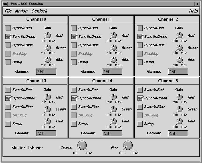
The MCO panel is a variation of the panel for RealityEngine graphics. If the system detects the presence of a Multi-Channel Option board, the panel appropriate for Multi-Channel Option board is displayed.
To run the MCO panel, follow these steps:
If necessary, run setmon as explained in the previous section.
Recable as necessary:
If no other monitors are available, use the standard 21-inch multisync monitor that comes with RealityEngine graphics.
If fewer monitors are available than there are outputs, cable to each Multi-Channel Option output in succession.
Start up the system. Log in as su.
At the prompt, type:
setenv DISPLAY :0.<pipe#>
usr/sbin/vout
Or, if it is possible to remotely log in from another system, do so; type
setenv DISPLAY <remote_system_name>:0
usr/sbin/voutIf the system has more than one MCO, for example, MCOs on pipes 0 through 2, you will have to run the vout panels locally by typing
setenv DISPLAY :0.0
/usr/sbin/vout
setenv DISPLAY :0.1
/usr/sbin/vout
setenv DISPLAY :0.2
/usr/sbin/vout
In releases after 5.1, use the -p flag to specify the pipe. For example, for MCOs on pipes 0 through 2, type
setenv DISPLAY :0.2
/usr/sbin/vout -p 0
setenv DISPLAY :0.2
/usr/sbin/vout -p 1
setenv DISPLAY :0.2
/usr/sbin/vout -p 2

Caution: Do not turn off SyncOnGreen or you will lose the display raster and the vout panel becomes unusable. This is one reason running the vout panel remotely is recommended. Figure 5-1 shows the panel.
To test panel functionality, use the dials to set gain for red, green, and blue output on various channels.
Do not save these values or you will corrupt the user values that the factory sets for the customer. The customer can change these values if desired.
Note: Setting coarse horizontal phase to maximum is not recommended; loss of lock can occur. To restore the settings to the factory settings, select "Restore Factory Values" in the File menu.
Note: For IRIX version 5.2 and later, user-defined settings are automatically in effect after they are saved. To activate user-defined settings for IRIX versions before 5.2, run vout after startup.
This section gives solutions for some common installation problems.
| Problem: | Vertical stripes appear on one or more channels, but not on all channels. | ||
| Solution: | Replace the VS2 board. This problem might be caused by an RM board. | ||
| Problem: | Vertical stripes appear on all channels. | ||
| Solution: | If the paddleboards were not carefully installed onto the VS2 and DG2 boards, the pins might have been bent. If replacing the paddleboards does not fix the problem, replace one of the following (listed in order of their likelihood of causing the problem):
| ||
| Problem: | One color is missing or the entire output of a channel is missing. | ||
| Solution: | Use these remedies, in order:
| ||
| Problem: | The hinv program does not see the MCO because the MCO's address is not in the DG2 EEPROM (EEPROM was erased or original DG2 was swapped out). | ||
| Solution: | For IRIX version 5.2 and later, do the following:
|
To test the Multi-Channel Option VME interface and DVI data path interface further, run the diagnostic tests; see Chapter 6, "Using Multi-Channel Option Diagnostics."