This chapter describes how to install an IP25 CPU board in an existing CHALLENGE or Onyx system.
Figure 2-1 provides an overview of the upgrade.
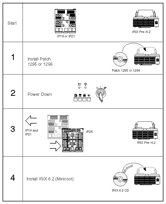
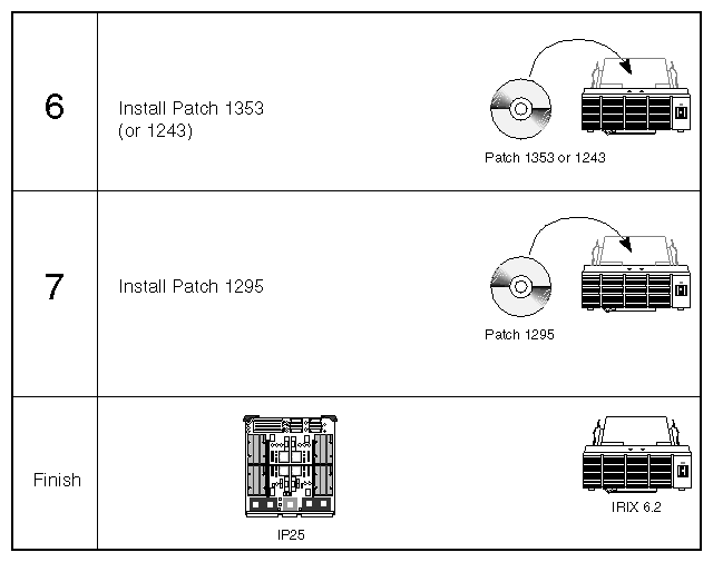
The steps to upgrade the system are:
Ensure that the system is stable.
Verify that you have all the required components before proceeding with the installation. See Section 2.2, "Checking the Kit Contents."
Verify that the customer's system has been backed up.
Install patch 1295 (for IRIX 5.3, 6.0, 6.1, and 6.0.1 systems) or patch 1296 (for IRIX 5.2 systems.) See Section 2.3, "Installing Patch 1295 or Patch 1296."
Power off the system, remove all other types of CPU boards, and check the card guides for excessive flex. Afterwards, install new IP25 boards. See Section 2.4, "Installing the IP25."
Check the new configuration using the PROM hinv command. See Section 2.5, "Verifying the System Configuration."
Install IRIX 6.2. See Section 2.6, "Installing IRIX 6.2."
Install patch 1353. Section 2.7, "Installing Patch 1353 (or 1243) and Patch 1295 on IRIX 6.2."
Install patch 1295. You must do this even if you installed patch 1295 earlier.
Pack and return the old CPU boards with their SRAM SIMMs in place. See Chapter 3, "Returning the Old CPU Board."
Be sure to follow the safety guidelines outlined in this section, before proceeding with the installation procedures.
 | Warning: Installation of these upgrades requires specific training and technical knowledge. These instructions are provided for use by Silicon Graphics system support engineers or other Silicon Graphics-trained personnel only. This equipment utilizes electrical power internally that is hazardous if the equipment is improperly disassembled. |

Follow these ESD-preventive measures:
Connect a ground strap to your wrist and the chassis when installing and removing peripherals.
Be sure that you and all of the electrical equipment that you handle during this installation remain at a ground potential of zero to avoid damage from ESD.
Remove a board from its antistatic bag only when you are properly grounded with a ground strap, and only when you are working on the board or installing it.
In addition, do not use an ohmmeter on a board.
The major contents of the IP25 upgrade kit are:
IP25 CPU board
Shipping box in which to pack the old CPU boards.
RMA form that the customer should return with the old CPU board.
 | Note: The RMA procedure has changed from prior upgrades. Be sure to read Chapter 3, "Returning the Old CPU Board" for new instructions. |
You will also need to have the following patches available:
Patch 1295
Patch 1296
Patch 1353 (or 1243 if 1353 is not available)
The above list is accurate as of this writing. However, you may wish to check the server patches.csd or the Web URL http://bits.csd.sgi.com/digest/patches/recommended to see if there are newer patches.
Patches 1295 and 1296 correct a potential problem with the IO4 PROM code and the flashio binary that can affect the IO4 boards in any CHALLENGE or Onyx deskside or rackmount system. The problem is that in rare cases, the version of the flashio binary that is on the system disk incorrectly flashes the main IO4 board when upgrading to IRIX 6.2. The result is that the system cannot be booted until you replace the main IO4 board.
The solution is to install these patches both before you install the IRIX 6.2 upgrade and after you install 6.2. The patches contain new firmware code for the IO4 PROMs and a new flashio binary. Table 2-1 describes which patches to install and which installation method to use (miniroot or live installation).
Table 2-1. Summary of Installation Methods for Patches 1295 and 1296
IRIX Version | Install Patch | Miniroot | Live |
|---|---|---|---|
6.2 (after upgrading) | dist/patchSG0001295.eoe_sw.unix | No | Yes |
5.3, 6.0, 6.0.1, 6.1 | dist/patchSG0001295.eoe1_sw.unix | No | Yes |
5.2 | dist-5.2/patchSG0001296.eoe1_sw.unix | Yes | No |
The procedure to install the patch on an IRIX 5.3, 6.0, 6.0.1, or 6.1 system is as follows:
Start Software Manager (swmgr) or Inst (inst).
Note: You must perform a live installation. You cannot install this patch from the miniroot. Use the CD containing patch 1295 and 1296 as the distribution source. The CD can be in a local CD-ROM drive or a remote CD-ROM drive.
Select dist/patchSG0001295.eoe1_sw.unix for installation.
With Software Manager, check the box for patchSG0001295.eoe1_sw.unix.
With Inst, type install dist/patchSG0001295.eoe_sw.unix and press <Enter>.
Start the installation.
With Software Manager, click the Start button.
With Inst, type go and press <Enter>.
When the patch is installed, quit from the installation program.
With Software Manager, pull down the File menu and select Quit.
With Inst, type quit and press <Enter>.
You are now ready to install the IP25 CPU board. Proceed with Section 2.4, "Installing the IP25."
The procedure to install the patch 1296 for an IRIX 5.2 system is as follows:
Before upgrading, shut the system down.
Load the patch CD containing patch 1295 and 1296 into a CD-ROM drive. The CD can be in a local CD-ROM drive or a remote CD-ROM drive.
From the System Maintenance menu, select the option to install system software.
Note: You must perform a miniroot installation You cannot perform a live installation. When prompted, indicate the location of the CD-ROM drive that contains the patch CD. The miniroot loads, during which time you see a variety of messages, and finally the Inst> prompt.
Type install dist-5.2/patchSG0001296.eoe1_sw.unix and press <Enter>.
Type go and press <Enter>.
When the installation is complete, type quit and press <Enter>. Inst displays some messages, then the system reboots.
You are now ready to install the IP25 CPU board. Proceed with Section 2.4, "Installing the IP25."
To install IP25 CPU board, you
verify the existing IRIX / (root) and /usr filesystem layout
shut down the system and remove the old CPU boards
check the chassis card guides for excessive flex.
install the IP25 board
Starting with IRIX 5.2, customers had the option of combining the / (root) and /usr filesystems into a single, large root filesystem. However, not all installations may be configured this way. Some may have separate / (root) and /usr filesystems and some may have a single, large root filesystem.
With IRIX 6.2, a single, large root filesystem is the standard configuration. This difference may require extra steps during the IRIX upgrade process to work around possible problems.
Verify the layout of the existing IRIX filesystems:
Log in as root.
Enter the following command at a shell prompt:
df -kl
Check the output of the df command to see if there are separate or combined root and /usr filesystems.
If there are separate / (root) and /usr filesystem, you see output similar to this:
Filesystem    Type   kbytes   use     avail   %use   Mounted on
/dev/root     efs     15365     9472    5893  62%    /
/dev/usr      efs    954492   748822  205670  78%    /usr
If there is a single, large root filesystem, you see output similar to this:
Filesystem    Type   kbytes   use     avail   %use   Mounted on
/dev/root     efs    969857   871720  98137   90%    /
Make a note of which type of layout is on the customer's system, and how much space is available. You will need this information when you reach Section 2.6, "Installing IRIX 6.2."
If the customer has separate / (root) and /usr filesystems, you will have to work around this constraint during the IRIX 6.2 upgrade.
Follow these steps to shut down the system:
Verify that the system has been backed up and that the backups are good.
Log in as root, then shut down IRIX using the shutdown command:
shutdown -g0
Turn the keyswitch on the System Controller Panel to Off.
Turn off the breaker on the back of the chassis.
Open the doors to the system.
Open the front card cage I/O door (deskside) or the door to the first card cage (rackmount).
Locate and remove the existing (non-IP25) CPU boards.
You are now ready to check the chassis card guides for excessive flex.
Some earlier models of CHALLENGE and Onyx systems use card guide supports that may flex excessively under the added weight of the IP25 board. Problems that can occur as a result of this flex include the following:
If the system is moved with the logic boards installed, electrical contacts between the midplane and various system boards can become loose, leading to POKA failures at startup and general system failures.
The connectors between a heavy board (such as the IP25) and the midplane may not line up correctly during installation, which can cause the connector pins to become crushed when you attempt to lock the board in place
A heavy board can disengage from the top card guide during installation, and fall over onto a neighboring board, potentially damaging both boards.
If the card guide supports flex excessively, advise the customer of the following:
Their system uses older style card guide supports that cannot be upgraded in the field.
Transporting this chassis with new, heaver logic boards (such as the IP25) installed is not a supported configuration.
The system will function normally as long as the customer does not move it and otherwise subject it to jostling and other physical stress.
The system can be moved without damage if
the logic boards (such as the CPU, memory, and IO4 boards) are first removed by a trained service technician
they are transported in proper containers
they are reinstalled into the chassis after transport
The customer may wish to purchase a new chassis if he or she expects to move the chassis often.
Reiterate that the system will function properly as long as it is not moved with the logic boards installed.
To install the new CPU board, follow these steps:
Recommended: Remove the blower assembly above the card cage.
Removing the blower assembly above the card cage allows you to visually inspect the connectors between the board and the midplane to be sure the board is properly aligned before you lock it in place.
Also, you can grasp the top of the board through the opening at the top of the card cage to help stabilize, support, and guide the board into place.
Install any IP25 boards that are part of this upgrade. They slide into the chassis the same way as other CPU boards (such as the IP19).
If you removed the blower assembly, reinstall it now.
Close the I/O door(s).
Close the chassis doors.
You are now ready to verify the hardware installation.
Follow these steps to verify that the system recognizes the IP25 board that you installed:
Turn on the circuit breaker at the rear of the system chassis.
Turn the keyswitch on the System Controller Panel to On.
Bring the system up to the System Maintenance Menu.
At the System Maintenance Menu, select option 5, Command Monitor.
At the Command Monitor prompt (>>), use the hinv command to verify that the IP25 board is correctly recognized:
>> hinv
You should see a listing similar to the following:
4 200 MHZ IP25 Processors
CPU: MIPS R10000 Processor Chip Revision: 2.5
FPU: MIPS R10010 Floating Point Chip Revision: 0.0
Data cache size: 32 Kbytes
Instruction cache size: 32 Kbytes
Secondary unified instruction/data cachesize: 1 Mbyte
Main memory size: 256 Mbytes, 2-way interleaved
I/O board, Ebus slot 11: IO4 revision 1
Integral EPC serial ports: 4
Integral Ethernet controller: et0, Ebus slot 11
Integral SCSI controller 1: Version WD33C95A
Disk drive: unit 2 on SCSI controller 1
Integral SCSI controller 0: Version WD33C95A
Disk drive: unit 1 on SCSI controller 0
Integral EPC parallel port: Ebus slot 11
CC synchronization join counter
VME bus: adapter 0 mapped to adapter 45
VME bus: adapter 45
The above listing shows a board with 4 CPUs.
If the IP25 board is not recognized, shut down the system and reseat the board. If it is still not recognized, the board may be bad. Obtain a replacement IP25.
If the board is recognized, exit from the Command Monitor with the following command:
>> quit
You are ready to install IRIX 6.2.
The IP25 CPU board requires IRIX 6.2 MR, or later. Prior releases of IRIX, including beta versions of IRIX 6.2, do not contain the necessary operating system code to support the IP25.
You must install IRIX 6.2 through the miniroot.
If you have not done so already, make sure a CD-ROM drive is either attached to the system or available via the network, and insert the IRIX 6.2 CD provided with the upgrade package into the drive.
At the System Maintenance Menu, enter option 2, Install System Software.
When prompted, enter the location of the CD-ROM drive that contains the IRIX 6.2 CD. The software begins loading and eventually you see the Inst prompt.
At the Inst prompt, enter:
install defaults
go
Once all the patches are installed, enter quit to exit from Inst. You are returned to the System Maintenance Menu.
Reboot the system to multiuser mode.
If you are not familiar with using Silicon Graphics software installation tools, see the Software Installation Administrator's Guide for more information about using Inst. (Once the system is running IRIX 6.2, refer to the newer guide IRIX Admin: Software Installation and Licensing, which is specific to IRIX 6.2.)
You are now ready to install more patches. Proceed with Section 2.7, "Installing Patch 1353 (or 1243) and Patch 1295 on IRIX 6.2."
After upgrading the operating system to IRIX 6.2, you must install the following patches:
patch 1353 (or 1243, if 1353 is not available)
patch 1295 (you must do this even if you installed patch 1295 earlier; the process of upgrading to 6.2 installs and older version of the flashio binary)
Use either Inst (inst) or Software Manager (swmgr) to install these patches in multiuser mode (a live installation.)
Follow these steps to install patch 1353. (If you are installing patch 1243 instead, use "1243" in place of "1353" in the commands below.)
Start Software Manager (swmgr) or Inst (inst).
Note: You must perform a live installation. You cannot install this patch from the miniroot. Use the CD containing patch 1353 as the distribution source. The CD can be in a local CD-ROM drive or a remote CD-ROM drive.
Select dist/patchSG0001353.eoe_sw.unix for installation.
With Software Manager, check the box for patchSG0001353.eoe_sw.unix.
With Inst, type install dist/patchSG0001353.eoe_sw.unix and press <Enter>.
Start the installation.
With Software Manager, click the Start button.
With Inst, type go and press <Enter>.
When the patch is installed, eject the patch CD from the CD-ROM drive.
You are now ready to install patch 1295. Proceed with Section 2.7.2, "Installing Patch 1295."
You should already have either Software Manager or Inst running. Follow these steps to install patch 1295:
Insert the CD containing patch 1295 into the CD-ROM drive.
Select the CD containing patch 1353 as the distribution source. The CD can be in a local CD-ROM drive or a remote CD-ROM drive.
Select dist/patchSG0001353.eoe_sw.unix for installation.
With Software Manager, check the box for patchSG0001353.eoe_sw.unix.
With Inst, type install dist/patchSG0001353.eoe_sw.unix and press <Enter>.
Start the installation.
With Software Manager, click the Start button.
With Inst, type go and press <Enter>.
When the patch is installed, quit from the installation program.
With Software Manager, pull down the File menu and select Quit.
With Inst, type quit and press <Enter>.
You are finished installing the IP25 board. You are now ready to repack the old CPU board and send it back to the factory. See Chapter 3, "Returning the Old CPU Board."
Although you are now finished installing the required hardware and software for the upgrade, this is a good time to verify with the customer that any software he or she ordered is installed on the system. This might include optional packages as compilers, NFS, and so forth.