This Chapter describes how to install a 200/250 MHz IP19 CPU board in an existing CHALLENGE or Onyx system.
Figure 2-1 provides an overview of the upgrade.
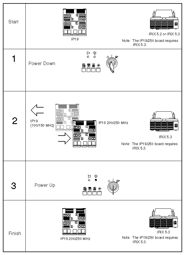
The steps to upgrade the system are:
Ensure that the system is stable and is already at the latest level of retrofit modifications. See Section 2.2, "Verifying the System Revision Level."
Verify that you have all the required components before proceeding with the installation. See Section 2.3, "Checking the Kit Contents."
Verify that the customer's system has been backed up.
If you are intermixing IP19 boards with different speeds and cache sizes, verify that the board versions are compatible. See Section 2.4, "Mixing and Matching IP19 Boards."
If you are upgrading to the IP191/250 MHz board(s), reflash the IO4 PROMs to version 3.17. See Section 2.5, "Flashing the IO4 PROM for IP19/250 MHz Upgrades."
Power off the system and remove all 100 MHz and 150 MHz IP19 boards if necessary. Afterwards, install new 200/250 MHz IP19 boards. See Section 2.6, "Installing the New IP19 Board."
Install additional software patches as required. See Section 2.7, "Installing the S/W Patch CD."
Check the new configuration using the hinv command. See Section 2.8, "Verifying the System Configuration."
Pack and return the old IP19 boards with their SRAM SIMMs in place. See Chapter 3, "Returning the Old IP19 Board."
Be sure to follow the safety guidelines outlined in this section, before proceeding with the installation procedures.
 | Warning: Installation of these upgrades requires specific training and technical knowledge. These instructions are provided for use by Silicon Graphics system support engineers or other Silicon Graphics-trained personnel only. This equipment utilizes electrical power internally that is hazardous if the equipment is improperly disassembled. |
Follow these ESD-preventive measures:
Connect a ground strap to your wrist when installing and removing peripherals.
Be sure that you and all of the electrical equipment that you handle during this installation remain at a ground potential of zero to avoid damage from ESD.
Remove a board from its antistatic bag only when you are properly grounded with a ground strap, and only when you are working on the board or installing it.
In addition, do not use an ohmmeter on a board.
Verify that the customer's system is at the retrofit-II level or later. The CHALLENGE and Onyx Retrofit II Requirements document (P/N 802-0113-001) describes the level at which a system must be to apply the retrofit II.
 | Note: Ensure that the system is stable and does not have any known problems. |
The major contents of the IP19 200/250 MHz upgrade kit are:
IP19 200 MHz board (two CPUs P/N 030-0652-001 and four CPUs P/N 030-0653-001)
IP19 250 MHz board (one CPU P/N 030-0806-001, two CPUs P/N 030-0805-001 and four CPUs P/N 030-0804-001)
Shipping box in which to pack the old IP19 boards.
RMA labels for old IP19s.
See Section 1.3, "IP19 Compatibility–Mixing Different CPU Speeds/Cache Sizes," for guidelines on intermixing different versions of the IP19 boards.
| Note: If you are intermixing IP19 CPUs with different clock speeds you also need to install patch 676. This patch enables the IRIX 5.3 kernel to support mixed IP19 speeds and cache sizes configurations. Consult the product release notes for additional information. |
The next part of the IP19/250 MHz upgrade process is to flash the IO4 PROM using code contained on patch 900 from the upgrade CD. The IP19/250 upgrade requires the IO4 PROM code level to be at 3.16 or higher. This new PROM code is necessary for the IO4 board to work with the IP19/250 board.
| Note: Patch 900 on the upgrade CD contains IO4 PROM revision 3.17. PROM version 3.16 (which was shipped on earlier IP19/250 MHz systems) works properly, but 3.17 is recommended. |
If you are upgrading to an IP19/200 MHz board, you do not need to reflash the IO4 PROM.
There are two ways to flash the IO4 PROM:
under the IRIX operating system using inst -f
through the command monitor (IO4 prompt) using flash -T
Either method produces the same result. However, the inst -f method is recommended, since it allows the system to have limited operability in case of a problem (see Section 2.5.2 for additional information). Just make sure that you do not reboot or issue the halt command if a failure should occur.
If you are not sure of the current IO4 PROM version, use one of these two methods.
At an IRIX shell as superuser, type the following:
# flashio -v
You should see a message similar to the following.
Slot 5: Flashprom version is 317
Bring the system to the command monitor level.
At the command monitor (IO4) prompt, enter:
>> version
You should see a display similar to the following.
IO4 PROM Monitor SGI Version 3.14 Rev A IP19
Note: The number 3.14 indicates that the IO4 PROM has been previously flashed with an IRIX 5.2.
This is the recommended IO4 flashing method. Follow the steps given below in this section to flash the IO4 PROM with IRIX running.
 | Caution: If the installation fails, do not reboot or halt the system. Instead, retry the installation. If the installation continues to fail, continue running the system until a replacement IO4 board can be obtained. It is very important to have the system running, so that the operating system tools and commands can be available to diagnose failures. |
Using an ASCII terminal, boot the system and log in as root.
Note: It is possible to run this procedure using a graphics monitor; however, it is generally safer to run the steps through an ASCII terminal in case the graphics subsystem fails during installation. (Optional) On a laptop computer, turn on the record option, or open up a script file so that you can record and later review problems that may occur during the upgrade.
Create a copy of the current IO4 flash code by typing the following command:
# cp /usr/cpu/firmware/IO4prom.bin /usr/cpu/firmware/io4prom.bin.save
Note: If the installation fails, you can use the original code to reflash the IO4 board. If a CD-ROM drive is not already installed on the system, install it now.
If required, mount the CD-ROM drive as shown in the following example:
mount -r /dev/dsk/dks0dns7/CDROM
where n is the address of the CD-ROM reader.
Install the IO4 PROM software from the upgrade CD distribution media using inst:
inst -f /CDROM/dist/io4prom
This copies a new PROM image (version 3.17) from the distribution CD (from patch 900) and reflashes the contents of the flash PROM in the IO4. This new flash code is required to boot the IP19/250 board and is backwards-compatible with other versions of the IP19 board. If multiple IO4 boards are present, all of these boards are flashed with the new PROM contents as well.
Note: No further steps are required to reflash any of the boards, including the IO4, GE10, or the old IP19. You should then see a display similar to the following:
Default location of new software is xxxxxx

If you are a first-time inst user, give the command "help beginner".

Inst Main Menu
 1. from [source]                 Specify location of software to be installed
 2. list [keywords] [names]       Display information about software subsystems
 3. go                            Perform software installation and removal now
 4. install [keywords] [names]    Select subsystems to be installed
 5. remove [keywords] [names]     Select subsystems to be removed
 6. keep [keywords] [names]       Do not install or remove these subsystems
 7. step [keywords] [names]       Enter interactive mode for instal/remove/keep
 8. versions [args]               Get information about installed software
 9. help [topic]                  Get help in general or on a specific word
10. admin                         Go to the Administrative Commands Menu
11. quit                          Terminate software installation
At the inst main menu, enter list to verify the software:
Inst> list

Reading installation history database
Reading product description from /CDROM/dist/io4prom:

io4prom IO4prom for 32bit OS systems, 5.3

i = installation requested            I = already installed
r = removal requested                 X = older version installed
k = no action/keep existing version   N = newer version installed

* = default subsystem at initial installation
@ = subsystem must be installed from the miniroot
+ = subsystem required for basic system functionality

Subsystems available for installation (list installable):

Subsystem Description

i io4prom.sw.prom * IO4prom binary
After verifying that the correct software is called out, enter go to begin installation.
Inst> go

Computing disk space changes:

Installing new versions of selected io4prom.sw subsystems

Installation and/or removal succeeded.
You can insert another tape or CD-ROM now.
Type "quit" if you are ready to leave the installation tool.
When the installation has completed, enter quit.
Inst> quit
#
If you see the following error message during this process, the IO4 board may be bad:
IO4 was not flashed correctly
If you see this message, do not reboot or halt the system until you can replace the IO4 board with a new board. After the IO4 board is replaced, return to this procedure to reflash the replacement IO4.
When the IO4 is successfully flashed, shut down IRIX with the shutdown command:
shutdown 0
Power off the system by turning the key on the System Controller panel.
Shut off the circuit breaker on the back of the system chassis.
You are now ready to install or swap out the IP19 boards. Proceed with Section 2.6, "Installing the New IP19 Board."
A second way to flash the IO4 PROM is to use the flash -T command through the command monitor. Some SSEs may prefer the command monitor method since it flashes only the microcode in the IO4 PROM, whereas the inst-f method flashes the microcode in both the IO4 PROM and the system disk.
If you have a flashing failure while using the inst-f method, you can potentially damage both the IO4 board and the hard disk. However, this problem is unlikely to occur. If you have a flashing failure using the command monitor method, the problem is limited to the IO4 board.
Follow these steps to flash the IO4 PROM through the command monitor:
Using an ASCII terminal, boot the system and log in as root.
Note: It is possible to run this procedure using a graphics monitor; however, it is safer to run the steps through an ASCII terminal in case the graphics subsystem fails during installation. Load the upgrade CD-ROM into the drive. If you do not have a CD-ROM, see steps 4 and 5 in Section 2.5.2, "Flashing the IO4 Under IRIX (inst -f)."
At the command monitor (IO4) prompt, enter:
>> version
You should see a display similar to the following.
IO4 PROM Monitor SGI Version 3.14 Rev A IP19
Note: The number 3.14 indicates that the IO4 PROM has been previously flashed with an IRIX 5.2. Enter hinv to find the controller number and ID number of the CD-ROM. You should see a display line similar to the following:
SCSI controller 0 cdrom(5)
Note: The display line specifies the controller number 0 and the ID number 5. This is very important information. You need to use these numbers later to access the contents of the CD-ROM to flash the IO4 PROM. Check if you can communicate with the CD-ROM by typing the following:
>> ls dksc(scsi controller#,CD-ROM ID#,8)
Note: The number 8 is the volume header section. Using the values obtained in our example, the command line would be:
>> ls dksc(0,5,8)io4prom
You should see a listing of the contents of the CD-ROM.
If you are able to communicate with the CD-ROM, flash the IO4 with the following command:
>> flash -T dksc(scsi controller#,CD-ROM ID#,8)io4prom
Using the values obtained in our example, the command line would be:
>> flash -T dksc(0,5,8)io4prom
Caution: Be sure to specify the -T (total) option. If you don't, only a portion of the IO4 PROM is erased by the flash command. As a result, there may not be enough memory space for the new IO4 PROM image and the flashing process will then fail. Reboot or reset the system after the flashing process is complete and proceed to Section 2.6, "Installing the New IP19 Board."
To install the new, 200/250 MHz IP19 board, follow these steps:
Verify that the system has been backed up and that the backups are good.
Log in as root, then shut down IRIX using the shutdown command:
shutdown -g0
Turn the keyswitch on the System Controller Panel to Off.
Turn off the breaker on the back of the chassis.
Open the doors to the system.
Open the front card cage I/O door (deskside) or the door to the first card cage (rackmount).
Locate and remove all IP19 boards.
Install any 200 or 250 MHz IP19 boards that are part of this upgrade.
Close the I/O door(s).
Close the chassis doors.
The IP19/250 MHz upgrade requires patch 900 and patch 676 as of the date of this publication. You may be required to install additional software patches from the patch CD.
| Note: For the additional patch information, consult the product release notes and check the patch distribution server, patches.csd. This server provides up-to-date patch information when you log on to the system. |
The patch software installs through the miniroot. Follow these steps to select a patch for installation:
At the Inst prompt, enter:
Inst> install patchSGxxxxxxx
where xxxxxxx is the number of the patch you wish to install.
Caution: You must specify each required patch, since you cannot install all the patches at one time. For example, if you give the command install default, you see the error desktop_tools.sw.tools requires desktop_eoe.sw.fam 1019999999. Select the desired patches for installation.
Once all the patches are installed, enter quit to exit from Inst.
Follow these steps to verify that the system recognizes the new, 200 or 250 MHz IP19 board that you installed:
Turn on the circuit breaker at the rear of the system chassis.
Turn the keyswitch on the System Controller Panel to On.
Bring the system up to the System Maintenance Menu.
At the System Maintenance Menu, select option 5, Command Monitor.
At the Command Monitor prompt (>>), use the hinv command to verify that the IP19 board is correctly recognized:
>> hinv
You should see a listing similar to the following:
4 200 <or> 250 MHZ IP19 Processors
CPU: MIPS R4400 Processor Chip Revision: 6.0
FPU: MIPS R4010 Floating Point Chip Revision: 0.0
Data cache size: 16 Kbytes
Instruction cache size: 16 Kbytes
Secondary unified instruction/data cache size: 4 Mbytes
Main memory size: 256 Mbytes, 2-way interleaved
I/O board, Ebus slot 11: IO4 revision 1
Integral EPC serial ports: 4
Integral Ethernet controller: et0, Ebus slot 11
Integral SCSI controller 1: Version WD33C95A
Disk drive: unit 2 on SCSI controller 1
Integral SCSI controller 0: Version WD33C95A
Disk drive: unit 1 on SCSI controller 0
Integral EPC parallel port: Ebus slot 11
VME bus: adapter 0 mapped to adapter 45
VME bus: adapter 45
The above listing shows a board with 4 CPUs.
Note: If you are mixing IP19 boards with different cache sizes (for example 1 MB with 4 MB), be aware that IRIX 5.3 hinv shows only the cache size of the master CPU board (that is, the CPU in the lowest numbered slot). If the IP19 board is not recognized, shut down the system and reseat the board. If it is still not recognized, the board may be bad. Obtain a replacement IP19.
If the board is recognized, exit from the Command Monitor with the following command:
>> quit
You are ready to start the system and finish the installation.
The final step to installing a 200/250 MHz IP19 board is to reboot the system.
At the System Maintenance Menu, enter option 1, Start System.
The system boots to multiuser mode.
You are finished installing the IP19 board. You are now ready to repack the old IP19 board and send it back to the factory. For RMA instructions, see Chapter 3, "Returning the Old IP19 Board."