This chapter introduces the Everest (POWERpath-2) board set and shows how those boards communicate over the various system and board buses. Figure 1-1 is a high-level functional block diagram of the Everest board set installed in a typical system. Figure 1-2 illustrates the IO4 board architecture in greater detail. As the individual diagnostic tools are discussed, similar diagrams highlight the areas affected by that tool (where appropriate).
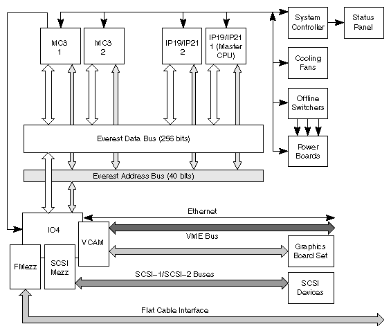
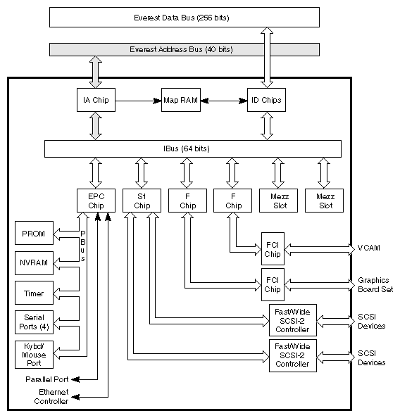
The available diagnostic tools are separated into six groups: parity checkers, power subsystem self-checks, power-on tests, power-on diagnostics (POD), the System Controller, and the integrated diagnostics environment (IDE).
Parity checkers are housed in the data and address bus ASICs on each system board, in the cache controller and CPU cache on the IP19 and IP21 boards, and in each interface ASIC on the IO4 board. The checkers are strategically placed to verify correct address and data parity at the system bus connectors, as well as at the on-board buses.
The power subsystem self-checks are automatic at power on and reset. Voltages not within the specified levels, or not present, cause the System Controller to halt the power-up sequence and display an error message. Error information is also provided by a series of LEDs on the off-line switchers and the system boards, but these are not visible without opening the cabinet.
The power-on tests execute whenever the system is powered on or reset. Those tests verify enough of the system's basic hardware functionality to load the standalone diagnostics from the IDE.
The power-on diagnostics (POD) is a special command interpreter that is a subset of the power-on tests. POD is automatically invoked by the PROM monitor in the event of an error during the boot process, or can be manually selected by the operator. POD provides an interface that allows the operator to inspect and modify various system parameters.
The standalone diagnostics are a series of functionality-oriented tests invoked from the PROM Monitor. They provide the highest degree of error isolation and the most accurate diagnosis but require their own environment (IDE) to run. Completion of the standalone diagnostics provides sufficient confidence in the system to attempt to boot UNIX®, but is not a guarantee.
Each group is described in detail in the following chapters.
Table 1-1 lists each bus found in a typical Everest deskside (L) or rackmount (XL) system.
Table 1-1. Bus Types in Everest Deskside and Rackmount Systems
Bus Category | Bus Types | Description |
|---|---|---|
Everest buses | Everest data and address buses (Ebus)
| Interconnects the system board set. |
| Polled Serial bus | Connects the system's CPU boards to the System Controller.
|
On-board buses | Interface bus (Ibus) | An internal bus on the IO4 board that connects the Ebus to the peripheral controllers and the board's optional interface (mezzanine) cards.
|
| Peripheral bus (Pbus) | Connects the Everest peripheral controller (EPC) chip on the IO4 board to a number of I/O ports, the NVRAM, and 1 MB of flash PROM. |
| Memory bus | Provides a path between the Ebus interface ASICs on the MC3 board and the memory array logic.
|
Peripheral buses
| SCSI buses | Connect a variety of storage devices to the IO4 board. The IO4 board has two built-in SCSI buses. By adding additional IO4 boards and SCSI mezzanine cards an Everest system can support up to 32 SCSI buses (depending upon the specific system configuration).
|
| Flat cable interface (FCI) | Connects the graphics cards or VMEbus to the IO4 board. Like the SCSI, multiple FCI buses can be supported by adding FCI mezzanine cards. In the standard configuration, 2 FCIs are on the IO4 board.
|
| VMEbus | Embedded in both the deskside and rackmount backplanes; available as an optional third cardcage (CC3) with the rackmount system.
|
Figure 1-3 shows a block diagram of the system buses
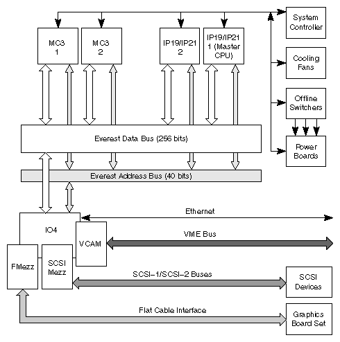
Each bus category is described in the following sections.
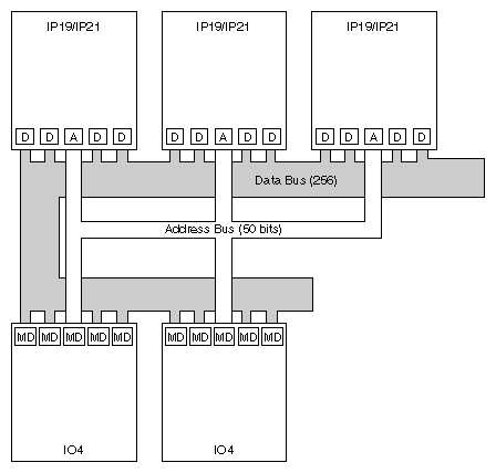
The Everest system buses consist of a 256-bit, 1200-MB/sec data bus, a 40-bit address bus, and the bus interfaces. The interfaces between the system buses and the Everest boards are supplied by a set of data and address ASICs (see Figure 1-4). There are four data ASICs (D chips) and one address ASIC (A chip) on each board. This logic is not identical from board to board but performs the same basic functions. Those interface chips perform parity checking on the data, address, and control lines during every bus cycle. There are eight parity lines on the data bus and two parity lines on the address bus. ASIC parity error detection is explained in more detail in Section 2.4, "ASIC Error Detection."
This dedicated bus is embedded in the system's backplane. It connects the system's CPU boards with the System Controller. During the boot process, the System Controller polls the CPU boards over this bus, requesting a bootmaster CPU. After the bootmaster is identified, all bring-up messages from the bootmaster CPU are sent to the System Controller display over the polled serial bus. The bootmaster CPU also outputs the bring-up messages to the system console RS-232 port (see Figure 1-5).
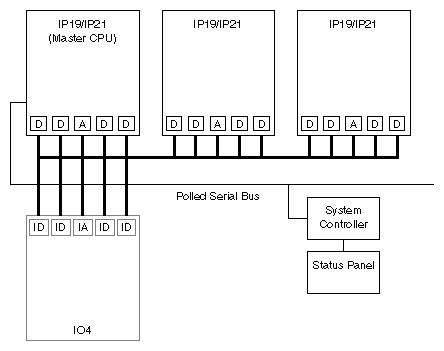
The polled serial bus provides a shortened error-reporting path to the System Controller display on the front panel. The path from the bootmaster CPU to the RS-232 system console port involves the Ebus and the IO4's Ibus. For error messages to reach the graphics monitor, they must pass through the graphics boards as well. Both of these error-reporting paths require a significant percentage of the system's hardware to be functional before an error can be reported.
When the PROM initializes, it reads the IA configuration registers to determine what kind of devices are connected to the Ibus. On the basis of the configuration information, the PROM runs a series of diagnostics that check the integrity of the Ibus and Pbus, as well as the functionality of the devices themselves. These diagnostics cannot distinguish between a bus failure and an ASIC failure, but they are sufficient to isolate a fault to the FRU (board) level.
The system supports 20-MB-per-second SCSI buses. These buses can be configured as single-ended or differential and as 8 or 16-bit. A five-digit drive address has been implemented to accommodate the large number of storage devices the Everest board set can manage. The first two digits represent the decimal slot number of the IO4 board. The third digit corresponds to the nth SCSI channel on the IO4 board (with possible SCSI mezzanine boards); zero and one are assigned to the two SCSI controllers on the IO4 board. Two through seven are assigned to the controllers on the mezzanine cards installed on the IO4. The fourth digit represents a specific drive; the fifth digit is the partition on the selected drive. See Figure 1-6 for an example of SCSI drive addressing.
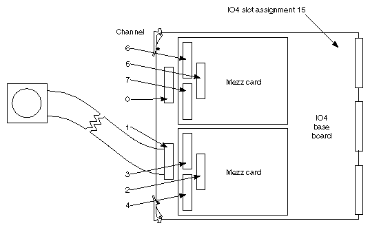
The flat cable interface (FCI) is a Silicon Graphics proprietary interface that connects a variety of local and remote peripheral resources, such as graphics controllers, VMEbus adapters, and FDDI adapters. The FCI operates at 160 MB per second (maximum) for graphics controllers and at a maximum of 200 MB per second with VMEbus adapters.
 | Note: The maximum effective VMEbus transfer rate may be in the range of 50 MB per second with DMA. The transfer rate is less with PIO-driven I/O. |