This chapter describes the signal connectors and cables for local and peripheral devices used with Challenge/Onyx systems.
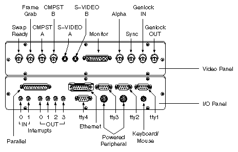
Standard device cabling is supported by one I/O board and its related connectors on a common I/O panel. For graphics systems, a second panel provides video connection. See Figure B-1. Table B-1 through Table B-9 provide a description of the connectors on the main I/O panel and provides a description of the connectors on the video panel.
Table B-18 and Table B-19 lists the signal pinouts for the 68-pin SCSI connectors on the system I/O panel. Table B-20 and Table B-21 provide 50-pin SCSI pinout details for reference information.
To attach more devices than are supported on the main I/O panel, additional hardware is required. Contact your local sales engineer for details.
Description | Pin | Signal | Flow (from chassis) |
|---|---|---|---|
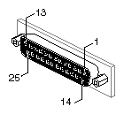
Parallel port. See Figure B-2. 25-pin D-sub receptacle. | 1 | STB (Data Strobe) |
|
| 2 | Data 0 |
|
| 3 | Data 1 |
|
| 4 | Data 2 |
|
| 5 | Data 3 |
|
| 6 | Data 4 |
|
| 7 | Data 5 |
|
| 8 | Data 6 |
|
| 9 | Data 7 |
|
| 10 | Data ACK |
|
| 11 | Busy |
|
| 12 | PE: Paper Empty |
|
| 13 | SLCT: Select/Online |
|
| 14 | AUTOFD |
|
| 15 | ERROR |
|
| 16 | INIT (reset) |
|
| 17 | SLCTIN |
|
| 18-25 | GND |
|
Description | Pin | Signal | Flow (from chassis) |
|---|---|---|---|
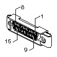
Ethernet port. See Figure B-3. 15-pin AUI (attachment unit interface) according to IEEE 802.3 specification. Pin pairs 2:9, 3:10, and 5:12 are twisted pairs. Cabling is 9-conductor. | 1 | Logic GND |
|
| 2 | Collision+ | two-way |
| 3 | TXD+ | two-way |
| 4 | Logic GND |
|
| 5 | RXD+ | two-way |
| 6 | Power Return | input |
| 7 | NC |
|
| 8 | Logic GND |
|
| 9 | Collision– | two-way |
| 10 | TXD– | two-way |
| 11 | Logic GND |
|
| 12 | RXD– | two-way |
| 13 | Power (+12V) | output |
| 14 | Logic GND |
|
| 15 | NC |
|
Description | Pin | Signal | Flow (from chassis) |
|---|---|---|---|
Serial port tty_1. See Figure B-4. 9-pin D-sub receptacle. RS-232 protocol. | 1 | NC |
|
| 2 | TXD | output |
| 3 | RXD | input |
| 4 | RTS | output |
| 5 | CTS | input |
| 6 | GND |
|
| 7 | GND |
|
| 8 | DCD | input |
| 9 | DTR | output |

Table B-4. Serial Ports tty_2, tty_3 for Unpowered Peripherals
Description | Pin | Signal | Flow (from chassis) |
|---|---|---|---|
Serial ports tty_2, tty_3 for unpowered peripherals. See Figure B-5. 9-pin D-sub receptacle. RS-232 protocol. Serial ports tty_2 and tty_3 provide a choice of 9-pin D-sub or an 8-pin DIN receptacle. (See below.) Only one receptacle from each port can be used at a given time. | 1 | not used |
|
| 2 | TXD | output |
| 3 | RXD | input |
| 4 | RTS | output |
| 5 | CTS | input |
| 6 | GND |
|
| 7 | GND |
|
| 8 | DCD | input |
| 9 | DTR | output |
Table B-5. Serials Ports tty_2, tty_3 for Powered Peripherals
Description | Pin | Signal | Flow (from chassis) |
|---|---|---|---|
Serials ports tty_2, tty_3 for powered
peripherals. See Figure B-6. | 1 | DTR | output |
| 2 | CTS | input |
| 3 | Stereo Sync | output |
| 4 | RXD | input |
| 5 | TXD | output |
| 6 | GND |
|
| 7 | GND |
|
| 8 | Power +10V | output |
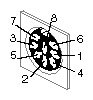
Table B-6. Serial Port tty_4 RS-422 Protocol
Description | Pin | Signal | Flow (from chassis) |
|---|---|---|---|
Serial port tty_4 | 1 | DTR | output |
| 2 | TXD low -[a] | two-way |
| 3 | RXD low -[b] | two-way |
| 4 | DCD | input |
| 5 | CTS | input |
| 6 | GND |
|
| 7 | TXD high +[c] | two-way |
| 8 | RXD high +[d] | two-way |
| 9 | RTS | output |
[a] Pins 2 and 7 must be twisted pair in cable. [b] Pins 3 and 8 must be twisted pair in cable. [c] Pins 2 and 7 must be twisted pair in cable. [d] Pins 3 and 8 must be twisted pair in cable. | |||
Table B-7. System Interrupt IN
Description | Pin | Signal | Flow (from chassis) |
|---|---|---|---|
System interrupt IN ports 0, 1. See | tip | Interrupt | input |
| ring | Power +5V |
|
| sleeve | Shield |
|

Table B-8. System Interrupt OUT
Description | Pin | Signal | Flow (from chassis) |
|---|---|---|---|
System interrupt OUT ports 0, 1, 2, 3. See | tip | Interrupt | output |
| ring | Power +5V |
|
| sleeve | Shield |
|
Table B-9. Keyboard/Mouse Port
Description | Pin | Signal | Flow (from chassis) |
|---|---|---|---|
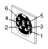
Keyboard/mouse port. See Figure B-10. 6-pin receptacle | 1 | KBD_RXD | input |
| 2 | MOUSE_RXD | input |
| 3 | SIG GND |
|
| 4 | Power +12V | output |
| 5 | KBD_TXD | output |
| 6 | NC |
|
Description | Pin | Signal | Flow (from chassis) |
|---|---|---|---|
Swap Ready port. See Figure B-11. BNC receptacle. Impedance 75 ohms. | center | SWAP_READY | two-way |
|
|
|
|

Description | Pin | Signal | Flow (from chassis) |
|---|---|---|---|
Frame Grab port. See Figure B-12. BNC receptacle. Impedance 75 ohms. | center | FRAME_GRAB | input |
|
|
|
|
Table B-12. Composite Video Ports A, B
Description | Pin | Signal | Flow (from chassis) |
|---|---|---|---|
Composite video ports A, B. See Figure B-13. BNC receptacle. Impedance 75 ohms. | center | CMPST_A or CMPST_B | output |
|
|
|
|
Table B-13. S-VIDEO Ports A, B
Description | Pin | Signal | Flow (from chassis) |
|---|---|---|---|
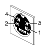
S-VIDEO ports A, B. See Figure B-14. | 1 | LUMOND | output |
| 2 | CHRMOND | output |
| 3 | LUM | output |
| 4 | CHRM | output |
Description | Pin | Signal | Flow (from chassis) |
|---|---|---|---|
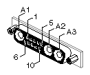
Monitor port. See
Figure B-15. | A1 | Red | output |
| A2 | Green | output |
| A3 | Blue | output |
| 1 | NC |
|
| 2 | Monitor type 0 | input |
| 3 | NC |
|
| 4 | Stereo Sync[a] | output |
| 5 | aStereo Power +10V | output |
| 6 | Monitor Type 1 | input |
| 7 | Monitor Type 2 | input |
| 8 | GND |
|
| 9 | aGND |
|
| 10 | aGND |
|
[a] On some cables these signals are NC. | |||
Description | Pin | Signal | Flow (from chassis) |
|---|---|---|---|
Alpha port. See Figure B-16. BNC receptacle. Impedance 75 ohms. | center | Alpha | output |
| shield | Chassis GND |
|
Description | Pin | Signal | Flow (from chassis) |
|---|---|---|---|
Sync port. See Figure B-17. BNC receptacle. Impedance 75 ohms. | center | Sync | output |
| shield | Chassis GND |
|
Table B-17. Genlock IN, Genlock OUT
Description | Pin | Signal | Flow (from chassis) |
|---|---|---|---|
Genlock IN, Genlock OUT. See Figure B-18. BNC receptacle. Impedance 75 ohms. | center | Genlock loop-through | two-way |
| shield | Chassis GND |
|
Table B-18. 68-pin, Single-ended, High-density SCSI Pinouts (See Figure B-19.)
Signal Name | Pin Number | Pin Number | Signal Name |
|---|---|---|---|
GND | 1 | 35 | -DB(12) |
GND | 2 | 36 | -DB(13) |
GND | 3 | 37 | -DB(14) |
GND | 4 | 38 | -DB(15) |
GND | 5 | 39 | -DB(P1) |
GND | 6 | 40 | -DB(0) |
GND | 7 | 41 | -DB(1) |
GND | 8 | 42 | -DB(2) |
GND | 9 | 43 | -DB(3) |
GND | 10 | 44 | -DB(4) |
GND | 11 | 45 | -DB(5) |
GND | 12 | 46 | -DB(6) |
GND | 13 | 47 | -DB(7) |
GND | 14 | 48 | -DB(P) |
GND | 15 | 49 | GND |
GND | 16 | 50 | GND |
TERMPWR | 17 | 51 | TERMPWR |
TERMPWR | 18 | 52 | TERMPWR |
Reserved | 19 | 53 | Reserved |
GND | 20 | 54 | GND |
GND | 21 | 55 | -ATN |
GND | 22 | 56 | GND |
GND | 23 | 57 | -BSY |
GND | 24 | 58 | -ACK |
GND | 25 | 59 | -RST |
GND | 26 | 60 | -MSG |
GND | 27 | 61 | -SEL |
GND | 28 | 62 | -C/D |
GND | 29 | 63 | -REQ |
GND | 30 | 64 | -I/O |
GND | 31 | 65 | -DB(8) |
GND | 32 | 66 | -DB(9) |
GND | 33 | 67 | -DB(10) |
GND | 34 | 68 | -DB(11) |
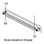
 | Note: Read the following information regarding the SCSI signal pinouts. A hyphen preceding a signal name indicates that the signal is active low. 8-bit devices that connect to the P-cable leave these signals open: -DB(8), -DB(9), -DB(10), -DB(11), -DB(12), -DB(13), -DB(14), -DB(15), -DB(P1). All other signals are connected as shown in this table. |
Table B-19. 68-pin, Differential, High-density SCSI Pinouts (See Figure B-20.)
Signal Name | Pin Number | Pin Number | Signal Name |
|---|---|---|---|
+DB(12) | 1 | 35 | -DB(12) |
+DB(13) | 2 | 36 | -DB(13) |
+DB(14) | 3 | 37 | -DB(14) |
+DB(15) | 4 | 38 | -DB(15) |
+DB(P1) | 5 | 39 | -DB(P1) |
GND | 6 | 40 | GND |
+DB(0) | 7 | 41 | -DB(0) |
+DB(1) | 8 | 42 | -DB(1) |
+DB(2) | 9 | 43 | -DB(2) |
+DB(3) | 10 | 44 | -DB(3) |
+DB(4) | 11 | 45 | -DB(4) |
+DB(5) | 12 | 46 | -DB(5) |
+DB(6) | 13 | 47 | -DB(6) |
+DB(7) | 14 | 48 | -DB(7) |
+DB(P) | 15 | 49 | -DB(P) |
DIFFSENS | 16 | 50 | GND |
TERMPWR | 17 | 51 | TERMPWR |
TERMPWR | 18 | 52 | TERMPWR |
Reserved | 19 | 53 | Reserved |
+ATN | 20 | 54 | -ATN |
GND | 21 | 55 | GND |
+BSY | 22 | 56 | -BSY |
+ACK | 23 | 57 | -ACK |
+RST | 24 | 58 | -RST |
+MSG | 25 | 59 | -MSG |
+SEL | 26 | 60 | -SEL |
+C/D | 27 | 61 | -C/D |
+REQ | 28 | 62 | -REQ |
+I/O | 29 | 63 | -I/O |
GND | 30 | 64 | GND |
+DB(8) | 31 | 65 | -DB(8) |
+DB(9) | 32 | 66 | -DB(9) |
+DB(10) | 33 | 67 | -DB(10) |
+DB(11) | 34 | 68 | -DB(11) |
| Note: Read the following information regarding the SCSI signal pinouts. A hyphen preceding a signal name indicates that the signal is active low. 8-bit devices that connect to the P-cable leave these signals open: -DB(12), -DB(13), -DB(14), -DB(15), -DB(P1), -DB(8), -DB(9), -DB(10), -DB(11), +DB(12), +DB(13), +DB(14), +DB(15), +DB(P1), +DB(8), +DB(9), +DB(10), and +DB(11). All other signals are connected as shown in this table. |
Table B-20. 50-pin Single-ended, Standard SCSI Pinouts (See Figure B-21.)
Signal Name | Pin Number | Pin Number | Signal Name |
|---|---|---|---|
GND | 1 | 26 | -DB(0) |
GND | 2 | 27 | -DB(1) |
GND | 3 | 28 | -DB(2) |
GND | 4 | 29 | -DB(3) |
GND | 5 | 30 | -DB(4) |
GND | 6 | 31 | -DB(5) |
GND | 7 | 32 | -DB(6) |
GND | 8 | 33 | -DB(7) |
GND | 9 | 34 | -DB(P) |
GND | 10 | 35 | GND |
GND | 11 | 36 | GND |
GND | 12 | 37 | GND |
Reserved | 13 | 38 | TERMPWR |
GND | 14 | 39 | GND |
GND | 15 | 40 | GND |
GND | 16 | 41 | -ATN |
GND | 17 | 42 | GND |
GND | 18 | 43 | -BSY |
GND | 19 | 44 | -ACK |
GND | 20 | 45 | -RST |
GND | 21 | 46 | -MSG |
GND | 22 | 47 | -SEL |
GND | 23 | 48 | -C/D |
GND | 24 | 49 | -REQ |
GND | 25 | 50 | -I/O |
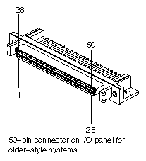
| Note: Read the following information regarding the SCSI signal pinouts. A hyphen preceding a signal name indicates that the signal is active low. The signal labeled "Reserved" is connected to ground in the bus terminator assemblies or in the end devices on the SCSI cable. The "reserved" line should be open in the other SCSI devices but may be connected to ground. |
| Note: The 50-pin SCSI connector is not available on the front panel of CHALLENGE/Onyx system. It is listed here for reference only. |
Table B-21. 50-pin, Differential, High-density SCSI Pinouts (See Figure B-22.)
Signal Name | Pin Number | Pin Number | Signal Name |
|---|---|---|---|
GND | 1 | 26 | GND |
+DB(0) | 2 | 27 | -DB(0) |
+DB(1) | 3 | 28 | -DB(1) |
+DB(2) | 4 | 29 | -DB(2) |
+DB(3) | 5 | 30 | -DB(3) |
+DB(4) | 6 | 31 | -DB(4) |
+DB(5) | 7 | 32 | -DB(5) |
+DB(6) | 8 | 33 | -DB(6) |
+DB(7) | 9 | 34 | -DB(7) |
+DB(P) | 10 | 35 | -DB(P) |
DIFFSENS | 11 | 36 | GND |
Reserved | 12 | 37 | Reserved |
TERMPWR | 13 | 38 | TERMPWR |
Reserved | 14 | 39 | Reserved |
+ATN | 15 | 40 | -ATN |
GND | 16 | 41 | GND |
+BSY | 17 | 42 | -BSY |
+ACK | 18 | 43 | -ACK |
+RST | 19 | 44 | -RST |
+MSG | 20 | 45 | -MSG |
+SEL | 21 | 46 | -SEL |
+C/D | 22 | 47 | -C/D |
+REQ | 23 | 48 | -REQ |
+I/O | 24 | 49 | -I/O |
GND | 25 | 50 | GND |
| Note: Read the following information regarding the SCSI signal pinouts. A hyphen preceding a signal name indicates that the signal is active low. The signals labeled "Reserved" are connected to ground in the bus terminator assemblies or in the end devices on the SCSI cable. The "reserved" lines should be open in the other SCSI devices but may be connected to ground. |
| Note: The 50-pin SCSI connector is not available on the front panel of CHALLENGE/Onyx system. It is listed here for reference only. |
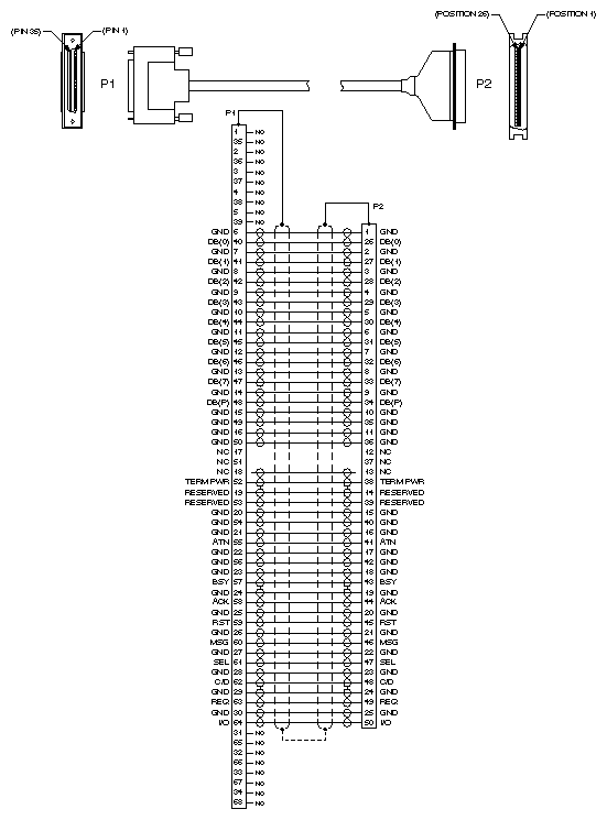
Table B-22 lists the different 68-pin to 50-pin SCSI converter cables available through Silicon Graphics. Figure B-23 illustrates the connectors for these cables.
Table B-22. 68-pin to 50-pin SCSI Converter Cable Types
Cable Part Number | Cable Type |
|---|---|
018-0347-xxx | 3-ft, external, single-ended SCSI cable |
018-0348-xxx | 15-ft external, single-ended SCSI cable |
018-0349-xxx | 50-ft, external, differential swizzle SCSI cable |
 | Caution: The 50-foot external, differential swizzle SCSI cable (P/N 018-0349-xxx) should be used only when connecting an CHALLENGE/Onyx L or XL system to a SCSIBox 1 (P/N P4-XBXD). Otherwise, damage could result to the SCSI devices, controller, and bus. |
This section identifies the monitor cables provided by Silicon Graphics. See Table B-23 for a summary of monitor cables and Table B-24 through Table B-29 for specific details of each cable.
Table B-23. Monitor Cable Summary
Description | Length | Connectors | Part Number |
|---|---|---|---|
Extension cable | 15' | 13W3 plug, both ends | 018-0285-001 |
Extension cable | 15' | 13W3 plug to 3 BNC plugs | 018-0286-001 |
Extension cable | 75' | 13W3 plug, both ends | 018-8094-002 |
Adapter cable | 1' | 13W3 receptacle to 3 BNC plugs | 018-0343-001 |
Adapter cable | 1' | 13W3 plug to 3 BNC receptacles | 018-0344-001 |
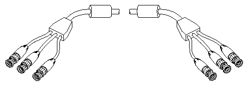
Extension cable | 75' | 3 BNC plugs, both ends | 018-0275-003 |
To attach a second graphics monitor to a Challenge/Onyx chassis, additional hardware is required to provide a second set of signals. Contact your local sales engineer for details.
Table B-24. Monitor Extension Cable, Round, 15' Length, Shielded, 13W3 Hybrid Plugs at Each End of Cable
Part Number | Description |
|---|---|
018-0285-001 | Monitor extension cable, round, 15' length, shielded, 13W3 hybrid plugs at each end of cable. See Figure B-24. |
Figure B-24. Monitor Extension Cable, Round, 15' Length, Shielded, 13W3 Hybrid Plugs at Each End of Cable
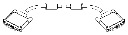 |
Table B-25. Monitor Extension Cable, Round, 15' Length, Shielded, 13W3 Hybrid Plug at Chassis End, 3 BNC Plugs (RGB) at Monitor End
Part Number | Description |
|---|---|
018-0286-001 | Monitor extension cable, round, 15' length, shielded, 13W3 hybrid plug at chassis end, 3 BNC plugs (RGB) at monitor end. See Figure B-25. |
Figure B-25. Monitor Extension Cable, Round, 15' Length, Shielded, 13W3 Hybrid Plug at Chassis End, 3 BNC Plugs (RGB) at Monitor End
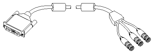 |
Table B-26. Monitor Extension Cable, Round, 75' Length, Shielded, 13W3 Hybrid Plugs at Each End of Cable
Part Number | Description |
|---|---|
018-8094-002 | Monitor extension cable, round, 75' length, shielded, 13W3 hybrid plugs at each end of cable. See Figure B-26. |
Figure B-26. Monitor Extension Cable, Round, 75' Length, Shielded, 13W3 Hybrid Plugs at Each End of Cable
|
Table B-27. Monitor Adapter Cable, Round, 1' Length, Shielded, 13W3 Hybrid Receptacle at One End, 3 BNC Plugs (RGB) at Other End
Part Number | Description |
|---|---|
018-0343-001 | Monitor adapter cable, round, 1' length, shielded, 13W3 hybrid receptacle at one end, 3 BNC plugs (RGB) at other end. See Figure B-27. |
Figure B-27. Monitor Adapter Cable, Round, 1' Length, Shielded, 13W3 Hybrid Receptacle at One End, 3 BNC Plugs (RGB) at Other End
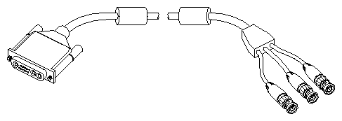 |
Table B-28. Monitor Adapter Cable, Round, 1' Length, Shielded, 13W3 Hybrid Plug at One End, 3 BNC Receptacles (RGB) at Other End
Part Number | Description |
|---|---|
018-0344-001 | Monitor adapter cable, round, 1' length, shielded, 13W3 hybrid plug at one end, 3 BNC receptacles (RGB) at other end. See Figure B-28. |
Figure B-28. Monitor Adapter Cable, Round, 1' Length, Shielded, 13W3 Hybrid Plug at One End, 3 BNC Receptacles (RGB) at Other End
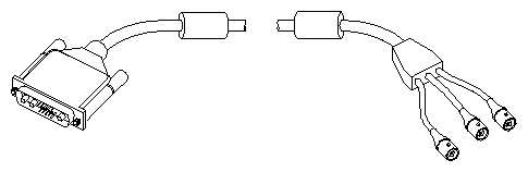 |
Table B-29. Monitor Extension Cable, Round, 75' Length, Shielded, 3 BNC Plugs (RGB) at Both Ends
Part Number | Description |
|---|---|
018-0275-003 | Monitor extension cable, round, 75' length, shielded, 3 BNC plugs (RGB) at both ends. See Figure B-29. |
The main keyboard (and mouse) connects to a dedicated port using a standard 30-foot cable. If a longer cable is required, order the 75-foot extension cable. These cables are shown in Table B-30 and Table B-31.
Table B-30. Keyboard/Mouse Extension Cable, Round, 30' Length, Shielded, 6-pin Circular Mini-DIN Plugs at Both Ends
Part Number | Description |
|---|---|
081-0345-001 | Keyboard/mouse extension cable, round, 30' length, shielded, 6-pin circular mini-DIN plugs at both ends. See Figure B-30. |
Figure B-30. Keyboard/Mouse Extension Cable, Round, 30' Length, Shielded, 6-pin Circular Mini-DIN Plugs at Both Ends
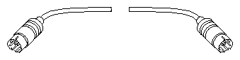 |
Table B-31. Keyboard/Mouse Extension Cable, Round, 75' Length, Shielded, 6-pin Circular Mini-DIN Plugs at Both Ends
Part Number | Description |
|---|---|
081-0075-001 | Keyboard/mouse extension cable, round, 75' length, shielded, 6-pin circular mini-DIN plugs at both ends. See Figure B-31. |
Figure B-31. Keyboard/Mouse Extension Cable, Round, 75' Length, Shielded, 6-pin Circular Mini-DIN Plugs at Both Ends
|
All other input devices connect to the chassis using serial ports. For detailed specifications, see Section B.5, "Serial Device Cables."
Serial devices connect to the chassis using four serial ports. Two serial ports support either powered devices (through the one of the two circular 8-pin DIN connectors) or unpowered devices (through tty_2 and tty_3). The serial port can support one of these connector types at a time. These two ports use the RS-232 protocol. A third serial port (tty_1) provides an unpowered connection using the RS-232 protocol. A fourth serial port (tty_4) provides connection for devices requiring the RS-422 protocol. See Table B-3 through Table B-6 for detailed specifications for each serial port.
The parallel port supports devices requiring a 25-pin Centronics®-compatible connection. See Table B-1 for detailed specifications for the parallel port.
Network cables can be attached to the network port using a 15-pin AUI receptacle. See Table B-2 for detailed specifications on the network port.
To determine cable lengths and other network details, read the material provided with the networking equipment, or refer to a networking guide.
To attach a modem to the system, connect a modem or null modem cable to one of the 9-pin serial connectors located on the I/O panel. If a 9-pin to 25-pin adapter is used, the adapter must be placed at the modem, and a cable with a 9-pin plug must be connected to the I/O panel. Placing an adapter directly on the chassis connector blocks the chassis door, which must be closed for proper operation.
| Note: This product requires the use of external shielded cables in order to maintain compliance with Part 15 of the FCC rules. Not all vendor serial cables are compatible with shielding requirements. |
Refer to the IRIX Advanced Site and Server Administration Guide for more information about modem configuration.
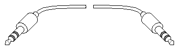
See Table B-32 for detailed specifications on the rackmount system interrupt cables.
Table B-32. Rackmount System Interrupt Cable
Part Number | Description |
|---|---|
9290054 | Rackmount system interrupt cable, round, 35' length, 3.5 mm 3-conductor plugs at both ends, wired straight-through. See Figure B-32. |