This chapter helps you identify and solve problems that might occur while you are using the SGI TP900 storage system. The following sections are covered:
The SGI TP900 enclosure includes a processor and associated monitoring and control logic to enable it to diagnose problems within the enclosure's power, cooling, and drive systems.
All rear-mounted modules are designed to be maintained by trained technicians. Each power supply module has a status LED.
A green LED is always a positive indicator, and an amber LED indicates that there is a critical fault within the module. The ESI/Ops panel displays the aggregated status of all the modules. The ESI/Ops panel LEDs are shown in Figure 4-1.
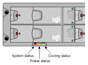
Table 4-1 summarizes the functions of the LEDs on the ESI/Ops panel and refers to the sections that cover specific component failures.
LED | LED State and Meaning | See This Section |
|---|---|---|
System status | Green signifies that power is applied to the enclosure. |
|
Power status | Green signifies that the power supplies are functioning normally. |
|
Cooling status | Green signifies that all fans are functioning normally. |
|
The following sections explain how to troubleshoot initial startup problems, system faults, power supply faults, and cooling module faults.
Check that you have wired the subsystem correctly. Call your supplier for a replacement part if:
Cords are missing or damaged.
Plugs are of the wrong type.
Cords are too short.
Use the following checklist if your computer does not recognize the SGI TP900 system:
Check that the Ultra-3 SCSI interface cables from the enclosure to the host computer are fitted correctly.
Check the SCSI ID settings on your system host.
Check that the LEDs on all installed drive carrier modules are illuminated green. Note that the drive LEDs will not be lit during drive spinup.
Check that all drive carrier modules have been correctly installed.
Check the I/O module setup as follows:
Check that the I/O module has been correctly installed and all external links and cables are securely fitted.
Check that the maximum cable length has not been exceeded; the maximum cable length is 10m for U160 and 3m for U320.
Check that the correct termination is fitted on all unused ports.
Check that different IDs have been selected for all devices on a channel.
Table 4-2 explains how to troubleshoot a system status LED that is amber.
Symptom | Cause | Action |
|---|---|---|
The system LED is amber. | The ESI processor has detected an internal fault. | 1. Check for other amber LED indicators on the power supply modules. If there is a PSU error, there may be a communications problem with that power supply module. Remove and then re-fit the module. If the problem persists, change the module. 2. Check for other amber LED indicators on the drive carriers. If none are evident, there may be either an ESI processor problem or a backplane problem. |
Table 4-3 explains how to troubleshoot a power supply module status LED that is amber.
Table 4-3. Power Supply Faults
Symptom | Cause | Action |
|---|---|---|
Operator panel power supply LED is amber. OR One or more power supply module LEDs are amber. | Any power fault. | 1. Check that the AC power connection to the power supply module is live. 2. Check that the power supply module is switched on. 3. Disconnect the power supply module from AC power, remove the module from the system, and then re-install it. If the problem persists, replace the power supply module. |
Table 4-4 explains how to troubleshoot a cooling module status LED that is amber.
Table 4-4. Cooling Module Faults
Symptom | Cause | Action |
|---|---|---|
Operator panel cooling LED is amber. | One or more fans within the cooling modules have failed | Remove the module(s) from the system, and then re-install it. If problem persists, replace the faulty cooling module. |