This chapter shows how to replace all plug-in modules in the SGI TP900 enclosure. The following sections are covered:
Observe the following safety precautions.
 | Warning: Hazardous voltage and current levels are present inside the storage subsystem. The replacement of rear-bay modules should be performed only by technically qualified personnel. |
 | Caution: Do not remove a module unless a replacement can be immediately added. The system must not be run without all modules in place. |
| Caution: Follow electrostatic discharge (ESD) precautions while replacing the plug-in modules. Avoid contact with the backplane components and module connectors. |
Ensure that you have obtained a replacement module of the same type before removing any faulty module.
| Caution: If the SGI TP900 subsystem is powered on and you remove any module, replace it immediately. If the subsystem is used without its modules or blanking plates for more than a few minutes, the enclosure can overheat, causing power failure and data loss. Such use will invalidate the warranty. |
If the enclosure contains two power supply modules, one of them can maintain power to the subsystem while the other is replaced. A cooling module can be replaced without SCSI data flow interruption. I/O modules can be replaced with the system powered up, but the SCSI Channel will be down and data flow will be interrupted.
Follow these steps to replace a power supply module or a power supply blank module on the SGI TP900 enclosure:
| Warning: Hazardous voltage and current levels are present inside the storage subsystem. The replacement of rear-bay modules should only be performed by technically qualified personnel. |
| Caution: Do not remove a module unless a replacement can be immediately added. The system must not be run without all modules in place. |
Switch off the faulty module and disconnect the power supply cord.

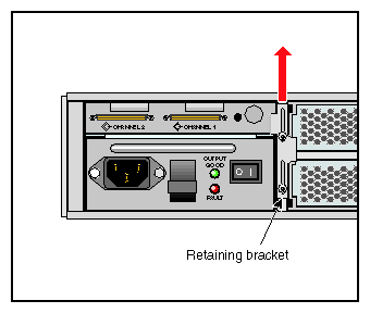
Note: If you have two power supply modules installed, one power supply module will maintain power to the enclosure while the other module is replaced. Loosen the screws securing the retaining bracket (see Figure 3-1) and slide the bracket upwards, until it is clear of the side of the power supply module.
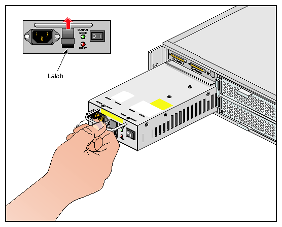
Grip the handle, lift the latch on the front of the PSU, and remove the PSU from the enclosure.
To install a replacement module, grip the handle, lift the latch on the front of the PSU, and slide the module into the enclosure (see Figure 3-2). The latch engages automatically.
Return the retaining bracket to the center position and tighten the securing screws.
Connect the power supply cord to the power source.
Follow these steps to remove a cooling module or a cooling blank module from the SGI TP900 enclosure:
| Caution: Do not remove a module unless a replacement can be immediately added. This is particularly important in a single-cooling module system which will very quickly overheat without a properly functioning cooling module installed. |
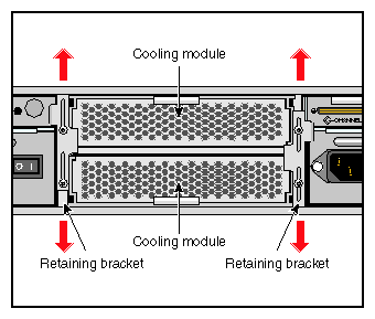
Loosen the screws securing both retaining brackets (see Figure 3-3), and slide the brackets up or down, depending on the location of the cooling module to be installed, until they are clear of the sides of the cooling module.
Slide the cooling module out of the enclosure.
Slide the replacement cooling module fully into the enclosure. You will feel a slight resistance as you set the cooling module connector in place and as the rear face of the tray is flush with the rear members of the enclosure.
Return the retaining brackets to the center position and tighten the securing screws.
Follow these steps to remove an I/O module from the SGI TP900 enclosure:
| Caution: Do not remove a module unless a replacement can be immediately added. The system must not be run without all modules in place. |
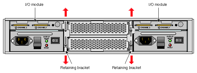
Loosen the screws securing the retaining bracket (see Figure 3-4) and slide the bracket down, until it is clear of the side of the I/O module.
Slide the I/O module out of the enclosure.
Slide the replacement I/O module fully into the enclosure. You will feel a slight resistance as you insert the card in the PCI connector and as the rear face of the I/O module becomes flush with the rear face of the PSU.
Return the retaining bracket to the center position and tighten the securing screws.
| Caution: Follow electrostatic discharge (ESD) precautions while replacing the drive carriers. Avoid contact with the backplane components and module connectors. |
Follow these steps to remove and replace a drive carrier module from the SGI TP900 enclosure:
| Caution: Do not remove a drive carrier unless a replacement or a dummy carrier can be immediately added. The system must not be run without all modules in place. Any unused drive bays must be fitted with a dummy carrier module. |
Spin down the drive prior to removal, using the operating system.
Caution: Damage can occur to a drive if it is removed while still spinning. If you cannot use the operating system to spin down the drives prior to removal, perform all steps of the following procedure to ensure that the drive has stopped prior to removal. Release the carrier handle by pressing the latch in the handle towards the right.
Note: The anti-tamper lock must be off. See “Engaging the Anti-tamper Locks” in Chapter 2 for instructions on disengaging the anti-tamper lock. Gently withdraw the drive carrier module approximately 1 inch (25mm), and then wait 30 seconds.
Withdraw the module from the drive bay.
Release the handle of the replacement carrier by pressing the latch in the handle towards the right, as shown in Figure 3-5. Insert the carrier into the enclosure.

Important: Ensure that the carrier is orientated so that the drive is uppermost and the handle opens from the left. Gently slide the carrier all the way into the enclosure until it is stopped by the camming lever on the right of the carrier, as shown in Figure 3-6.
Push the carrier handle into place—the camming foot on the base of the carrier will engage in a slot in the enclosure. Continue to push firmly until the handle fully engages. A click should be heard as the latch engages and holds the handle closed.
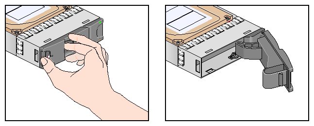
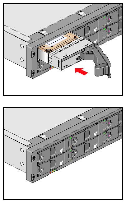
Table 3-1 lists part numbers for the following replaceable components.
Table 3-1. Component Part Numbers
Component | Part Number |
|---|---|
Power supply module | 013-3437-001 |
I/O module | 013-3436-001 |
Loopback module U320 | 013-4187-001 |
Cooling module | 013-3438-001 |
Bifurcated power cable | 7260832 |
Dummy drive carrier | 013-3439-001 |
Terminator U160/U320 | 9660121 |