The SGI TP900 is a 2U-high 8-drive storage system that provides compact, high-capacity, high-availability JBOD (“just a bunch of disks”) storage for supported SGI servers. The enclosure backplane connects the 8 drives on one SCSI bus. As an option, the storage system can also be configured on two SCSI busses (two strings of 4 drives). The SGI TP900 is rack-mountable and is designed to use SCSI Parallel Interface 3 (SPI-3) capable Low Profile (1-inch high) 3.5-inch disk drives. The drive carriers accept SGI-qualified 10,000 or 15,000 rpm U160/U320 SCSI disk drives.
This chapter gives information on the basic features of the SGI TP900 SCSI storage system in the following sections:
The basic unit of the SGI TP900 storage system is the enclosure, which contains the disk drives arranged in two rows of 4 drives, and the drive backplane in the front. The I/O, power supply (PSU), and fan modules are located at the rear of the chassis. The chassis uses two EIA units of rack space, and is fitted with 19-inch rack-mounting features, which enable it to be mounted into standard 19-inch racks.
Figure 1-1 shows the front of the enclosure, with the full complement of 8 disk drive modules.

Figure 1-2 shows the back of an enclosure, which contains one of each of the following: cooling module, cooling blank module, PSU module, PSU blank module, I/O module, and I/O loopback module.

Blank modules occupy unoccupied empty bays and must be in place for proper operation and to ensure correct airflow. The component modules are discussed in detail in “Plug-in Modules”.
Figure 1-3 shows the back of a fully configured redundant enclosure with two cooling modules, two PSU modules, and two I/O modules.
The Enclosure System Interface/Operators (ESI/Ops) panel consists of three status indicator LEDs that are located on the front of the enclosure. The ESI/Ops panel provides the enclosure with a micro controller that is used to monitor and control all elements of the enclosure. Each element (system, power, and cooling status) is interfaced to the processor. Figure 1-4 shows the ESI/Ops panel.
Table 1-1 summarizes the functions of the LEDs on the ESI/Ops panel. See Chapter 4, “Troubleshooting” for descriptions of common problems, with possible solutions, that can occur with your SGI TP900 system.
LED | LED State and Meaning |
|---|---|
System status | Green signifies that power is applied to the enclosure. |
Power status | Green signifies that the power supplies are functioning normally. |
Cooling status | Green signifies that all fans are functioning normally. |
The front of the enclosure contains 8 drive bays, each of which accommodates a plug-in drive carrier module. The rear of the enclosure contains 6 module bays that house power supply, cooling, and SCSI I/O modules. This section describes the component modules in the storage system, as follows:
The drive carrier module comprises a hard disk mounted in a carrier. Each drive bay will house a single 1.0-inch high, 3.5-inch disk drive in its carrier. Each disk drive is enclosed in a die-cast aluminum carrier that provides excellent thermal conduction, radio frequency and electromagnetic induction protection, and maximum physical protection of the drives.
The front cap also supports an ergonomic handle that provides the following functions:
Camming of carrier into and out of drive bays.
Spring-loading of the drive into the backplane connector.
An anti-tamper lock operated by a torx socket type key.
Figure 1-5 shows a drive carrier module.

This section discusses other features of the drive carrier module, as follows:
Drive carrier indicators
Anti-tamper locks
Drive information label
Each drive carrier incorporates two indicators, an upper (green) and a lower (amber). In normal operation, the green indicator will be lit and will flicker as the drive operates. Figure 1-6 shows the drive carrier indicators.
Anti-tamper locks are fitted in the drive carrier handles and are accessed through the small cutout in the latch section of the handle. These are provided to disable the normal “pinch” latch action of the carrier handle. See “Engaging the Anti-tamper Locks” in Chapter 2 for instructions on how to engage or disengage the anti-tamper lock. Figure 1-7 shows the location of the anti-tamper locks.
| Note: The drives will operate with the locks either engaged or disengaged. |

A label containing drive information is located on the drive carrier handle. The label indicates the size (xxx GB), speed (xx kRPM), and the last five numbers of the serial number of the drive installed in the carrier. See Figure 1-8 for an illustration of the drive information label.
One 350-Watt plug-in power supply module (PSU) is mounted in the rear of the system. Optionally, a second power supply module can be fitted to provide redundancy. Figure 1-9 shows a PSU module.
Power supply voltage operating ranges are nominally 115 V or 230 V, and are selected automatically.
In a redundant configuration, the modules operate together; if one fails, the other maintains the power supply while the faulty unit is replaced.
| Important: Module replacement should only take a few minutes to perform but must be completed within 10 minutes from removal of the failed module. Alternatively, if a replacement power supply module is not available, a power supply blanking module must be fitted after removing the faulty module. |
Two LED indicators are located on the front panel of the power supply. Figure 1-10 shows the power supply indicators.

The green LED indicates good power output. The amber LED indicates power supply failure.
Two I/O modules are mounted in the rear of the system utilizing Ultra-3 SCSI interfacing with the host computer system. Two I/O module configurations are available, as follows:
The 1 x 8 configuration is used to create a SCSI bus structure with one string of 8 drives. It consists of one standard I/O module with two VHDCI connectors for main I/O purposes and a switch to set the SCSI-ID range. The second module is a loopback PCB with no external connectors.
The 2 x 4 configuration is used to create a SCSI bus structure with two strings of 4 drives. The two modules are the standard I/O modules with two VHDCI connectors for main I/O purposes.
Figure 1-11 shows a standard Ultra-3 I/O module.
Figure 1-12 shows the rear view of an enclosure with I/O modules in a 1 x 8 configuration.
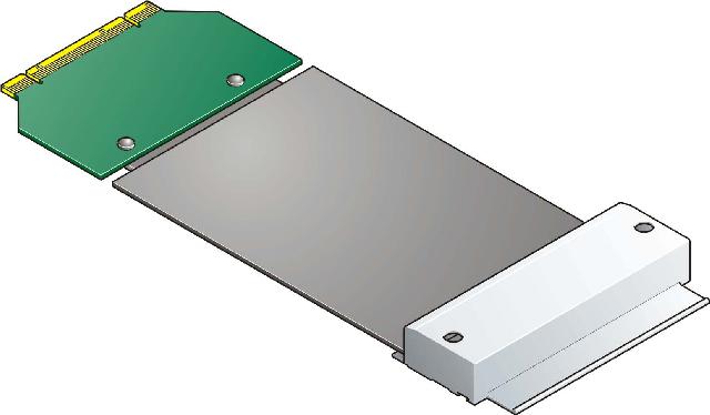
Figure 1-13 shows a U160/U320 loopback module.
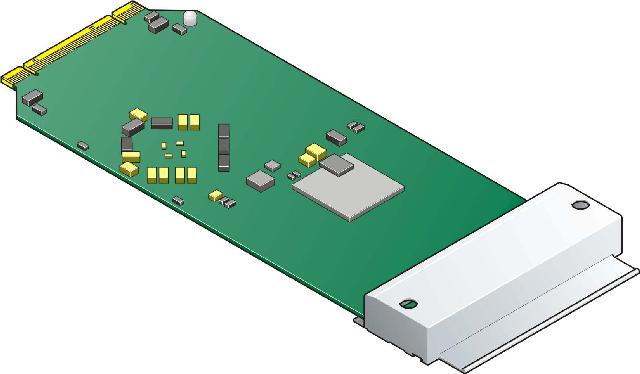
Figure 1-14 shows a U160 loopback module.
One cooling plug-in module is mounted in the rear of the system. Optionally, a second cooling module can be fitted to provide greater redundancy. The cooling modules connect to the backplane for power and status signal connections. The modules pull air from a plenum behind the drive backplane and exhaust the warm air at the rear of the enclosure. Figure 1-15 shows a cooling module.
In a redundant configuration, the modules operate together; if one fails, the other maintains adequate cooling to the system while the faulty unit is replaced.
| Caution: Do not remove a module unless a replacement can be immediately added. This is particularly important in a single-cooling module system, which will very quickly overheat unless a properly functioning cooling module is installed. |
Dummy carrier modules are provided for installation in all unused drive bays. They are designed as integral drive module front caps with handles and must be installed in all unused drive bays to maintain a balanced airflow.
Blank modules must be fitted in all vacant bays at the rear of the enclosure to maintain airflow and ensure correct operation. Blank modules are available for the cooling module bays and the power supply module bays.
A bay is defined as the space required to house a single module. In the front of the enclosure, this is the space required by a single 1.0-inch high 3.5-inch disk drive in its carrier module. In the rear of the enclosure, this is the space required by a single PSU, I/O, or cooling module.
The SGI TP900 system has 8 drive bays in the front of the enclosure—2 rows of 4 bays. A front bay is identified by a row/column fraction. Rows are numbered 1 to 2 from top to bottom, and columns are numbered 1 to 4 from left to right, viewed from the front. For example, drive 1/2 refers to the bay located in row 1 (top) and column 2 (second from the left).
Figure 1-16 shows the numbering convention for the drive modules.
The SGI TP900 system has 6 module bays at the rear—2 rows of 3 bays. A rear bay is identified by a row/column fraction. Rows are numbered 1 to 2 from top to bottom, and columns are numbered 1 to 3 from right to left, viewed from the rear. For example, module 2/3 refers to the bay located in row 2 (bottom) and column 3 (third from the right).
Figure 1-17 shows the location and numbering convention for the rear-bay modules.