Installation of the SGI Media Server includes configuring it to work with the following types of external devices:
Devices that control the SGI Media Server. These devices include the following:
Devices that the SGI Media Server controls. These include most broadcast VTRs using the Sony-compatible RS-422 control protocol.
Devices through which media is played or recorded. These devices include PCI-VIDAUD-MSB-B cards for digital video playback and recording with DVCPRO 25, DVCPRO 50, DVCAM, DV (16-bit/48 Khz audio only), or MPEG-2 compression format.
Auxiliary devices, such as your timecode readers.
This chapter explains installing and configuring these devices in the following sections:
The Sony ( P2) protocol is partially supported by Video Server Technology (VST) so that the server can be controlled by standard VTR controllers. The configuration information makes the server behave similar to a video tape deck.
 | Note: P2 is an alternate name for the Sony protocol. For the remainder of the chapter, the term “Sony” represents both Sony and P2. |
The following sections describe how to configure the server to work with the Sony protocol:
“Changing the Clip Loaded in a Sony Controlled Logical Unit”

Caution: Opening a unit owned by a Sony port using MVCP commands (for example, UOPN) causes unpredictable behavior and is unsupported.
The SGI Media Server does not currently support the entire Sony protocol specification. It does not support the following:
Video output parameter selection
Audio output parameter selection
Audio split editing
Insert editing for anything less than all video/audio tracks
+/-15% playback/recording/editing
Note: VAR_FORWARD and VAR_REVERSE are fully implemented.
To configure Sony protocol control ports, follow these steps:
As root, use the following command to verify that the vst_eoe.sw.sony subsystem is installed:
# /usr/vtr/bin/vtrswinfo -subsys -short
 Installed software:
vst_eoe (1279037220)
    vst_eoe.man.base (1279037220)
    vst_eoe.man.ftpd (1279037220)
    vst_eoe.man.relnotes (1279037220)
    vst_eoe.man.tools (1279037220)
    vst_eoe.sw.base (1279037220)
    vst_eoe.sw.clipmirror (1279037220)
    vst_eoe.sw.diaquest (1279037220)
    vst_eoe.sw.ftpd (1279037220)
    vst_eoe.sw.little-red (1279037220)
    vst_eoe.sw.louth (1279037220)
    vst_eoe.sw.merlin (1279037220)
    vst_eoe.sw.merlin_fw (1279037220)
    vst_eoe.sw.mfcodec (1279037220)
    vst_eoe.sw.mpeg (1279037220)
    vst_eoe.sw.sony (1279037220)
    vst_eoe.sw.tools (1279037220)
If necessary, install the Sony subsystem.
Cable the controlling device to the SGI Media Server. For more information about cabling an RS-422 device to a server, see “RS-232 and RS-422 Cabling”.
For each Sony device controlled by the SGI Media Server, enter a line in file /usr/vtr/config/control-in.conf. See “Configuring the SGI Media Server for Control by Remote Devices ” in Chapter 3 for instructions.
Edit the control defaults file for each Sony control port as needed.
The directory /usr/vtr/config/system_defaults contains files specifying the default control settings for system-wide resources, including the control processors managing any Sony protocol control ports.
Put control settings that apply to all Sony control ports in vtr.
Put control settings that are limited to specific control ports in vtr_port, where port is the server serial port number to which the controlling device is attached; for example, vtr_1, vtr_2, and so on.
The following controls are supported by the Sony control module:
See the vst-controls(5) man page for more information concerning the use and default values of these controls.
An application can change these controls dynamically with the MVCP SSET command; they can also be queried using the MVCP SGET command. For example:
SSET vtr_1 vtr.control.clip.name new-clip
This example creates the clip new-clip, if it does not already exist, and loads it onto the units controlled by the device attached to serial port 1.
Note: The setting for vtr.control.output.idle_mode overrides the setting for vtr.media.output.idle_mode of the underlying device. Make sure that the EDIT-ON/EE-ON delay time for your edit controller matches the delay time set by VST controls.
The Sony deck control protocol was originally developed to control VTRs, thus it has no facility for clip management operations including the loading and unloading of clips. The control vtr.control.clip.name can be set to change the clip currently loaded.
The GUI application mcclips (see “The Clip Manager” in Appendix A for more information on mcclips) enables you to load and unload clips on ports controlled by the Sony protocol. To load a clip, for example, follow these steps:
Select a clip.
Select File > Load On Port.
You can also create a new clip on a port:
Select a clip.
Select File > Create On Port.
An application can load a new or existing clip onto the units controlled by a Sony protocol device by using the MVCP SSET command to set the value of vtr.control.clip.name (see the vst-controls(5) man page).
The SGI Media Server provides frame-accurate control for a VTR or VTR-like device that supports the industry-standard Sony compatible VTR RS-422 control protocol. The VTR can be controlled interactively through a user interface or through an application for frame-accurate captures and laydowns of clips. To configure the SGI Media Server to control a VTR, follow these steps:
As root, enter the following to verify that the vst_eoe.sw.diaquest subsystem is installed:
# /usr/vtr/bin/vtrswinfo -subsys -short

 Installed software:
 vst_eoe (1279037220)
    vst_eoe.man.base (1279037220)
    vst_eoe.man.ftpd (1279037220)
    vst_eoe.man.relnotes (1279037220)
    vst_eoe.man.tools (1279037220)
    vst_eoe.sw.base (1279037220)
    vst_eoe.sw.clipmirror (1279037220)
    vst_eoe.sw.diaquest (1279037220)
    vst_eoe.sw.ftpd (1279037220)
    vst_eoe.sw.little-red (1279037220)
    vst_eoe.sw.louth (1279037220)
    vst_eoe.sw.merlin (1279037220)
    vst_eoe.sw.merlin_fw (1279037220)
    vst_eoe.sw.mfcodec (1279037220)
    vst_eoe.sw.mpeg (1279037220)
    vst_eoe.sw.sony (1279037220)
    vst_eoe.sw.tools (1279037220)
If necessary, install the Diaquest subsystem.
Cable the SGI Media Server to the VTR. For more information about cabling an RS-442 device to an SGI Media Server, see “RS-232 and RS-422 Cabling”.
For each Sony device controlled by the SGI Media Server, enter a line in file /usr/vtr/config/control-out.conf. See “Configuring the SGI Media Server to Control Other Devices ” in Chapter 3 for instructions.
The following example shows the control-out.conf configuration line for a VTR connected to serial port 3:
sony rs422 3 38400 1
Edit the control defaults file as needed.
The directory /usr/vtr/config/device-defaults contains files specifying the default control settings for VST devices, including external VTRs controlled by the SGI Media Server.
Put control settings that apply to all controlled VTRs control ports in dq.
Put control settings that are limited to a specific controlled VTR in file dq_port, where dq_0 is for the first controlled VTR in file control-out.conf, dq_1 is for the second controlled VTR in file control-out.conf, and so on.
The following are the only controls supported by the Diaquest VTR control module:
-
To guarantee frame-accurate control, the control vtr.media.video.sync_port must be set to the name of the SGI Media Server video port that is connected to the VTR. The application mcpanel does this automatically, but other applications must ensure that the control is set correctly. For example, the following entry instructs the system to use the first serial connection defined in file control-out.conf and to use MFCODEC_1 instead of MFCODEC_0 as the related video I/O port:
mcpanel -D dq_0 -p MFCODEC_1
If the same SGI Media Server video port is always used with the VTR, you can set the value of vtr.media.video.sync_port to the name of the video port in the appropriate dq_port device defaults file. However, if the controlled VTR might be connected to different SGI Media Server video ports at different times, set the control using the MVCP SET command. For example, before performing a frame-accurate capture from the controlled VTR to the MFCODEC_2 video port, set the following control:
SET dq-unit-name MED vtr.media.video.sync_port MFCODEC_2
For information on the controls, see the vst-controls(5) man page.
Put the VTR into remote (or slave) mode.
Repeat all these steps for as many VTRs as you wish to control and as are connected to the SGI Media Server.
The Video Disk Communications Protocol ( VDCP) provides full-featured control of the SGI Media Server using an RS-422 or TCP/IP connection. The Harris Automation ADC100 controller is such a controller. Connected to the SGI Media Server, a VDCP processor supports the following:
Back-to-back play and record (subject to restrictions imposed by the video I/O port capabilities)
Control of multiple video (signal) ports from a single communications (control) port
Caution: Do not open any units (using the MVCP command UOPN) belonging to a VDCP control protocol processor in order to control them.
This section consists of these subsections:
Table 7-1 summarizes the VDCP commands that the SGI Media Server supports.
Table 7-1. VDCP Commands Supported by the SGI Media Server
Command Type | Commands |
|---|---|
System | Delete Protect ID |
Immediate | Stop |
Reset/Select | Reset Std. Time |
Sense Request | Open Port |
An ADC100 Harris Automation controller is connected to the SGI Media Server using one or two serial ports per the video port to be controlled. If you want to play and record at the same time, two serial port connections are required, unless you are using VDCP multiport command support.
Follow these steps to connect and configure an ADC100 Harris Automation controller:
Cable the automation controller to the SGI Media Server. For more information about cabling an RS-442 device to the SGI Media Server, see “RS-232 and RS-422 Cabling”.
Configure the automation controller. The information in Table 7-2 specifies how to configure a Harris Automation ADC100 to control the SGI Media Server. If you are using another automation controller that uses VDCP, you might need to configure that controller in a similar way.
Configure each communications port that controls one or more video ports to use the standard VDCP.
Table 7-2. Harris Automation Device Parameters
Device Parameter
Setting
VIDEO INPUT PORT IN DISK
Video port number (corresponds to signal configuration line in file control-in.conf)
VIDEO OUTPUT PORT IN DISK
Video port number (corresponds to signal configuration line in file control-in.conf)
UPDATE EVENT DURATIONS FROM DISK
Enabled only on one port for each server
CONFIGURE INSTANT PLAY PREROLLS
Enabled, 0 seconds 4 frames
NUMBER (=) OF FRAMES TO SEND PLAY EARLY
3 frames (DVCPRO)
ENABLE BACK TO BACK PLAY
3 frames (DVCPRO)
ENABLE BACK TO BACK RECORD
3 frames (DVCPRO)
DISK HAS ARCHIVE
Enabled if an archival system is available; otherwise disabled
BACKUP PLAY FROM ARCHIVE SUPPORTED
Disabled
CACHE RECORD DISK SERIAL COMM. PORT NUMBER
0
For each Harris Automation communications port connected to a serial port, include a control port configuration line in the file /usr/vtr/config/control-in.conf. See section “Control Port Configuration Line” in Chapter 3 for configuration instructions and examples and section “RS-232 and RS-422 Cabling” for cabling instructions.
For each video port to be controlled through VDCP, include a signal port configuration line like that described in “Control Port Configuration Line” in Chapter 3.
Example 7-1 shows the control-in.conf file for a configuration where VDCP is used to control four playout codecs and two input codecs. The Harris Automation communications ports that controls the playout codecs are connected to the SGI Media Server serial ports 3 through 6 and control MFCODEC_2 through MFCODEC_5, respectively. The communications ports controlling the ingest codecs are connected to serial ports 7 and 8 and control MFCODEC_0 and MFCODEC_1, respectively. Note that a “–” prefix denotes an input signal port. Both ingest ports use an input latency of 6 frames.
| Note: The records containing the louth entries are using a legacy name required for this specific purpose. |
Example 7-1. Configuration File Specifications for VDCP Port Control
louth rs422 3 38400 1 3 29.97 louth rs422 4 38400 1 4 29.97 louth rs422 5 38400 1 5 29.97 louth rs422 6 38400 1 6 29.97 louth rs422 7 38400 1 -1 29.97 clips=path1/* louth rs422 8 38400 1 -2 29.97 clips=path2/* signal 1 MFCODEC_0 signal 2 MFCODEC_1 signal 3 MFCODEC_2 signal 4 MFCODEC_3 signal 5 MFCODEC_4 signal 6 MFCODEC_5 |
The configuration records contain an additional optional field, the clip pathname prefix. By default, ingested clip content is placed in directory /usr/vtr/clips. The clip pathname prefix field permits you to specify an arbitrary and relative (relative to /usr/vtr/clips) prefix for the clip path.
As shown in Example 7-1, ports 7 and 8, corresponding to MFCODEC_0 and MFCODEC_1, will have their ingested clip content placed in directories /usr/vtr/clips/path1 and /usr/vtr/clips/path2, respectively. MFCODEC_2 and MFCODEC_3, if used for ingest purposes, will both use the directory /usr/vtr/clips as the content ingest path.
The SGI Media Server supports the Miranda Little Red and Horita PR-232 timecode. Their readers translate LTC to RS-232 timecode. Either of these devices provides a frame-accurate time reference to an external timecode generator. With such a reader attached, the SGI Media Server operations can then be synchronized with other studio equipment or with scheduled live or downlink feeds.
The timecode signal connected to the SGI Media Server is used as the reference for triggering timed-based commands for playback and recording. Frame accuracy is guaranteed within the limits defined by the specifications for the SGI Media Server.
The time-of-day signal is also used to slave the time-of-day maintained by the IRIX operating system. The time-of-day is typically maintained within one millisecond of the input time signal.
To install a timecode reader and configure the SGI Media Server for it, follow these steps:
Connect the timecode reader's serial port to the desired RS-232 port on the SGI Media Server.
Install vst_eoe.sw.little-red.
Include a control port configuration line in the file /usr/vtr/config/control-in.conf. See “Signal Configuration Line” in Chapter 3 for more information. Note the following:
For timecode input, the signal port field (“signalport” in Chapter 3) of the configuration line specifies the time channel number, which must be 1 for this release of the SGI Media Server.
Both the Miranda Little Red and Horita PR-232 timecode readers connect at a serial port speed of 9600 bits per second with no parity.
The following example shows the control-in.conf file for a Horita PR-232 connected to serial port 3:
hsip rs232 3 9600 0 1 29.97
This example shows a Miranda Little Red in a 625/50 configuration:
little-red rs232 3 9600 0 1 25
Add a line for each device to control-in.conf to configure the SGI Media Server to work with Horita and the Miranda Little Red timecode readers. The following is an example:
hsip rs232 3 9600 0 1 29.97
little-red rs232 2 9600 0 1 29.97
The format of the configuration line is explained in “Configuring the SGI Media Server for Control by Remote Devices ” in Chapter 3.
The vtr.time.offset control specifies the offset (in nanoseconds) between the actual timebase and the decoded input timecode. This offset accounts for delays in the timecode reader, in the serial communications with VST, and in VST time processing. Use the SSET command to change the value, or set this value in /usr/vtr/config/system-defaults/main. The following is an example for the Little Red:
SSET main vtr.time.offset -27000000
See http://www.miranda.com/pdf/manual for documentation on the Little Red device and http://www.horita.com for information on the PR-232.
This section gives an overview of cabling an RS-422 connector between a Harris Automation controller and the XIO DB-9 connector on the SGI Media Server. Figure 7-1 shows the pinouts for the RS-232 and RS-422 protocols.
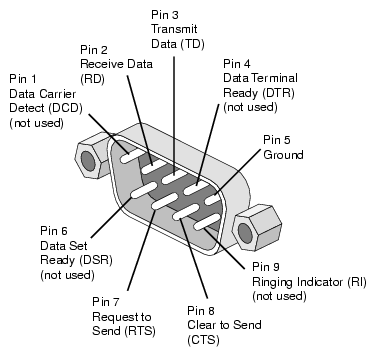
Table 7-3 describes the pin assignments for the RS-232 and RS-422 protocols.
Table 7-3. DB-9 Pin Assignments
Pin | RS-232 Mode | RS-422 Mode |
|---|---|---|
1 | DATA CARRIER DETECT (DCD) | RESERVED |
2 | RECEIVE DATA (RXD) | RECEIVE DATA (RXD) |
3 | TRANSMIT DATA (TXD) | TRANSMIT DATA (TXD) |
4 | DATA TERMINAL READY (DTR) | TRANSMIT DATA+ (TXD+) |
5 | GROUND | SIGNAL GROUND |
6 | DATA SET READY (DSR) | RECEIVE DATA+ (RXD+) |
7 | REQUEST TO SEND (RTS) | OUTPUT HANDSHAKE (HSKo) |
8 | CLEAR TO SEND (CTS) | INPUT HANDSHAKE (HSKi) |
9 | NOT CONNECTED | RESERVED |
Proper pinouts for passing RS-422 input from Mini-Din connectors to DB-9 connectors are described in the following tables. The Mini-Din connectors are those found on the Menet board. The Menet board can be identified by its six serial ports and four Ethernet ports. There are also notes for RJ12/16 and RJ45 connectors.
A proper adapter from Mini-Din to DB-9 uses the configuration shown in Table 7-4.
Table 7-4. Configuration for a Mini-Din to DB-9 Adapter
Male 8-pin Mini-Din | Female DB-9 |
|---|---|
3 (TX-) | 8 (RX-) |
4 (GND) | 1 (GND) |
5 (RX-) | 2 (TX-) |
6 (TX+) | 3 (RX+) |
8 (RX+) | 7 (TX+) |
A proper adapter from DB-9 to RJ12/16 may be needed. For a Harris Automation controller, Table 7-5 shows how this adapter should look.
Table 7-5. Adapter for Harris Automation Controller (DB-9 to RJ12/16)
DB-9 Pin (Male/Female) | Signal | RJ12/16 6-Pin |
|---|---|---|
Pin 3 | TXB+ | Pin 1 |
Pin 8 | TXA- | Pin 2 |
Pin 2 | RXA- | Pin 2 |
Pin 7 | RXB+ | Pin 4 |
Pin 4 | TX Shield | NC |
Pin 6 | RX Shield | NC |
Table 7-6 shows the pin assignments for an RS-422 serial port to an RJ-45 cable connector.
Table 7-6. Pin Assignments—RS-422 Serial Port to an RJ-45 Cable Connector
Connector | Green Pin | Red | Orange Pin | Black Pin |
|
|---|---|---|---|---|---|
Origin 300 DB-9 Male | 4 (TX+) | 3 (TX-) | 6 (RX+) | 2 (RX-) | 7 (HSKo) 8 (HSKi) 5 (GND) |
XIO MENET/MSER Board with Macintosh Mini-Din-8 to DB-9 Female Adapter | 4 (TX+) | 5 (TX-) | 8 (RX+) | 9 (RX-) |
|
Sony (Panasonic AG-A850 or Buf RM-4000) controller DB-9 Female (Master/DCE) | 7 (RXb) | 2 (RXa) | 3 (TXb) | 8 (TXa) |
|
Sony VTR DB-9 Female (Slave/DTE) | 3 (TXb) | 8 (TXa) | 7 (RXb) | 2 (RXa) |
|
Notes:
These pinouts are valid between an Origin system and a system not an Origin. For peer-to-peer Origin communications, configure ports as RS-232 and use a standard modem/null-modem cable. For peer-to-peer Sony communications, straight-through cables are required. Hence, they both must be slave or both be master.
SGI P/N# 018-0650-001 6-inch Mini-Din 8 to DB-9 male adapter described in the XIO MENET/MSER Board Installation Instructions cannot be used for RS-422 because pin 8 (RX+ on the Mini-Din 8 end) has no corresponding pin at the DB-9 end.