This chapter describes the power, rack space, PCI, and video/audio connections required to install and set up an SGI Media Server. The following sections detail these requirements:
This chapter describes setting up your system in the following sections:
Power requirements for the Origin 350 base platform supporting the SGI Media Server are shown in Table 2-1. It includes the power requirements for the 2U-high PCI-X expansion module also.
Table 2-1. Power Requirements for the SGI Media Server Base Unit
Specification | Value |
|---|---|
Input volts | 110 or 220 volts, 20 amp universal auto-switching power supply |
Power bay output | 640 watts DC (3.3/5/12v) |
Cooling | N+1 redundant cooling |
 | Note: A power redundancy option is available. |
Power bay requirements for the 4U-high PCI expansion module are shown in Table 2-2.
Table 2-2. Power Requirements for the PCI Expansion Module Power Bay
Specification | Value |
|---|---|
Input volts | 110 or 220 volts. The power bays are not universal and do not autoswitch. The default power bay has two offline switcher (OLS) power supplies. They should be in slots 4 and 5 in the power bay. One power bay can drive six I/O bricks with power. Up to six OLSs can be installed in one power bay. A power bay supplies AC voltage and monitors and controls the peripheral I/O brick power units. |
Power output | Each distributed power supply inputs single-phase AC power and can output a maximum of 950 watts at 48 VDC. The outputs are bussed together to provide a maximum of 3,800 watts of available peak power in an N+1 redundant configuration. This means there is one additional 950 watt power supply for reserve. The reserve power supply is ready-standby and will power the system in case of failure. |
Cooling | N+1 redundant cooling units. A minimum of two power supplies must be present. |
Table 2-3 shows the power and size specifications for external RAID storage systems.
Table 2-3. Power and Size Specifications for the External RAID Storage System
Specification | Value |
|---|---|
Input Volts | Dual internal rack power distribution to enclosures, single phase, 250 VAC (180 minimum, 257 maximum), 50/60 Hz, 16A (25A circuit breakers) |
Dimensions | 13.34 cm x 44.45 cm x 50.0 cm (5.25” x 17.5” x 19.68”) for height, width, and depth, respectively |
Weight | Approximately 35 kg (77 lbs) fully loaded, 9 kg (19 lbs) empty |
A 2-channel SGI Media Server requires three standard rack units and an 8-channel SGI Media Server requires seven rack units. The SGI Media Server occupies a standard 19-inch rack. In addition, each external SGI TP900 disk array requires 2 rack units, and each SGI TP9100 disk array requires 3 rack units each and resides in a standard 19-inch rack.
The following sections show the space requirements for sample configurations for the SGI Media Server.
Table 2-4 shows the rack space requirements for a two-channel Model 325 with TP900 storage.
Table 2-4. Two-Channel Model 325 Space Requirements
Component | Rack Space (U) |
|---|---|
Origin 300 or Origin 350 (2-CPU) with 2 PCI-VIDAUD-MSB-B cards | 2 |
1 MSB-REARPANEL-B panel | 1 |
RM 610 disk array | 2 |
Table 2-5 shows the rack space requirements for a four-channel Model 345 with TP900 storage.
Table 2-5. Four-Channel Model 345 Space Requirements
Component | Rack Space (U) |
|---|---|
Origin 350 (4-CPU) with 2 PCI-VIDAUD-MSB-B cards | 2 |
PCI expansion module with 2 PCI-VIDAUD-MSB-B cards | 2 |
2 MSB-REARPANEL-B panels | 2 |
RM 610 disk array | 2 |
Table 2-6 shows the rack space requirements for a six-channel Model 365 with TP9100 storage.
Table 2-6. Six-Channel Model 365 Space Requirements
Component | Rack Space (U) |
|---|---|
Origin 350 (4-CPU) with 2 PCI-VIDAUD-MSB-B cards | 2 |
Compute expansion module | 2 |
PCI expansion module with 4 PCI-VIDAUD-MSB-B cards | 2 |
3 MSB-REARPANEL-B panels | 3 |
1 TP9100-2G FC-AL RAID disk array | 3 |
Table 2-7 shows the rack space requirements for an eight-channel Model 385 with TP9100 storage.
Table 2-7. Eight-Channel Model 385 Space Requirements
Component | Rack Space (U) |
|---|---|
Origin 300 or Origin 350 (4-CPU) with 2 PCI-VIDAUD-MSB-B cards | 2 |
PCI expansion module with 6 PCI-VIDAUD-MSB-B cards | 4 |
4 MSB-REARPANEL-B panels | 4 |
1 TP9100-2G FC-AL RAID disk array | 3 |
Power bay | 3 |
This section presents general requirements for the PCI bus and sample configurations for the SGI Media Server.
For optimal performance the PCI video/audio cards ( PCI-VIDAUD-MSB-B cards), storage, and networking cards should not be mixed with cards of different types while sharing the same bus. Table 2-8 outlines supported bus speeds for each type of add-on card.
Note that the table uses the acronym FC HBA for Fibre Channel host bus adapter.
Table 2-8. Supported Bus Speeds for Optimal Add-On Cards
Add-On Cards | 33Mhz | 66Mhz | 100Mhz |
|---|---|---|---|
Gigabit Ethernet, Tigon-2 (eg n) | X | X |
|
Gigabit Ethernet, Tigon-3(tg n) | X | X | X |
1-Gigabit single-port FC HBA with PCI | X | X |
|
2-Gigabit single-port FC HBA with PCI | X | X |
|
2-Gigabit dual-port FC HBA with PCI or PCI-X |
| X | X |
PCI-VIAUD-MSB-B card | X |
|
|
Serial I/O card | X |
|
|
Cards that support only 33Mhz bus speed will cause the PCI bus to lock to 33Mhz. This can degrade performance of networking and storage cards that support 66Mhz bus speeds or higher.
In the section “Recommended Card Layouts”, specific card layouts are recommended. Some optional/alternative configuration recommendations are also made. The following is a list of general guidelines for card placement on an SGI Media Server:
Do not use cards of different types on the same bus. However, in fully configured systems this may not be possible.
PCI-VIDAUD-MSB-B boards are always to be put in the specific slots shown in section “Recommended Card Layouts”.
Never mix a PCI-VIDAUD-MSB-B card with networking or Fibre Channel/SCSI disk HBA cards.
PCI-VIDAUD-MSB-B cards may share the same bus with serial boards, if necessary.
Serial boards may share the same bus with Gigabit Ethernet cards. However, there will be some loss of networking performance.
Keep disk and networking cards on separate buses. However, they can be put on the same bus but there may be some overall degradation in both disk and network performance.
Note: SGI does not support configurations that share serial boards with Fibre Channel HBAs on the same bus.
The tables in this section recommend card layouts for the SGI Media Server infrastructure. They represent only standard minimum and maximum configuration options.
The following two conventions are used in the tables:
Optional slot layout possibilities are in parentheses.
The descriptors “best choice” and “last choice” are used for serial cards to indicate card placement priority, where “last choice” indicates that you only use this bus/slot if no other slots are available.
Table 2-9 shows the layout of the three internal PCI slots available on the Origin 350. The Origin 350 also provides a console port (serial I/O) and two additional integrated serial ports that can be used for VDCP control of two PCI-VIDAUD-MSB-B boards. The integrated UltraSCSI interface can be used with the TP900 (if configured). A primary network interface (TX-1000) is also provided.
Table 2-9. Origin 350 Internal PCI Slot Layout
Bus | Slot | Recommended Card Layout for Internal Slots Module (001c01) | Xtalk | Slot |
|---|---|---|---|---|
2 | 1 | PCI-VIDAUD-MSB-B card1 | 15 | 1 |
2 | 2 | PCI-VIDAUD-MSB-B card2 | 15 | 2 |
1 | 1 | (Gigabit Ethernet)(33Mhz-only cards—last choice)1 | 15 | 1 |
1. See the introductory text for section “Recommended Card Layouts” for conventions used in the table.
For both Model 345 and Model 365, Table 2-9 shows the internal PCI slot layout for the Origin 350 base compute module. The base compute module houses two video cards.
For a four-channel Model 345 system, place the two additional video cards on bus 1 of the PCI expansion module (PX2U).
For a six-channel Model 365 system, place the additional four video cards on bus 1 and bus 2 of the compute expansion module.
Table 2-10 shows the recommended layout for the PE brick on SGI Media Server configurations for the Origin 350 base unit.
The bus and slot information is printed on back of the PE brick just above each slot. The xtalk/slot numbers are available by using the command vtrhwinfo. Each PCI-VIDAUD-MSB-B board will report its xtalk/slot number and the table in this section can be used to find the appropriate bus/slot number. This applies for all other cards as well.
Table 2-10. PE Brick Layout for Origin 350 Systems
Bus | Slot | Recommended Card Layout for PE Brick Module (001p02) | Xtalk | Slot |
|---|---|---|---|---|
1 | 1 | (Gigabit Ethernet)1 | 9 | 1 |
1 | 2 | (Serial--last choice)1 | 9 | 2 |
2 | 1 | Fibre Channel | 8 | 1 |
2 | 2 | (Fibre Channel)1 | 8 | 2 |
3 | 1 | PCI-VIDAUD-MSB-B card3 | 15 | 1 |
3 | 2 | PCI-VIDAUD-MSB-B card4 | 15 | 2 |
4 | 1 | PCI-VIDAUD-MSB-B card5 | 14 | 1 |
4 | 2 | PCI-VIDAUD-MSB-B card6 | 14 | 2 |
5 | 1 | PCI-VIDAUD-MSB-B card7 (Serial)1 | 12 | 1 |
5 | 2 | PCI-VIDAUD-MSB-B card8 (Serial)1 | 12 | 2 |
6 | 1 | Serial—best choice1 | 13 | 1 |
6 | 2 | Serial—best choice1 | 13 | 2 |
1. See the introductory text for section “Recommended Card Layouts” for conventions used in this table.
The SGI Media Server can contain up to eight channels of video I/O, employing the SGI PCI-VIDAUD-MSB-B card. Connections to the card are made through the MSB-REARPANEL-B component. This section provides connection and configuration information for the rear panel and the audio/video card.
| Note: References to PCI-VIDAUD-MSB-B cards in this section also apply to PCI-VIDAUD-MSB-C, PCI-VIDAUD-MSB-IMX, and PCI-VIDAUD-MSB-IMX-C cards. |
PCI-VIDAUD-MSB-B cards are half-size, 64-bit, 33MHz, 3.3V PCI cards. The cards, along with the VST software, provide encoding and decoding of the following video formats:
The card supports the following audio I/O types:
AES/EBU
Embedded
Analog
The audio and video connections to the card are made through the rear panel of the SGI Media Server. The panel and connections are described in the following subsections.
The MSB-REARPANEL-B provides the physical audio and video connections to the SGI Media Server. A rackmounted unit supports up to two video/audio cards (channels) in the server. Each rear panel has two sets of video and audio connectors—one set for each of two audio/video cards (PCI-VIDAUD-MSB-B). Figure 2-1 shows the left-half, front view of the rear panel and shows all but one SDI video connector. The right half of the rear panel is identical to the left half with matching connectors and labeling conventions.
| Note: The rackmounted rear panel requires a 19-inch connector break-out-box. |
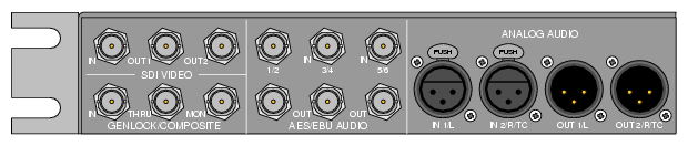
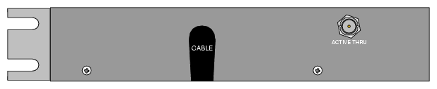
Figure 2-2 depicts the left-half, rear view and shows a single ACTIVE THRU SDI connector. As with the front of the panel, the rear halves are identical.
The MSB-REARPANEL provides SDI and GENLOCK/COMPOSITE video connectors.
Table 2-11 provides a description of each SDI video connector.
Table 2-11. SDI Video Connectors
Connector | Description |
|---|---|
IN | This connector is the video input for the PCI-VIDAUD-MSB-B card. The input may contain a maximum eight channels of embedded digital audio conforming with the SMPTE 272M standard. |
OUT1 | This connector is video Output 1 for the PCI-VIDAUD-MSB card. The output may contain a maximum eight channels of embedded digital audio conforming with the SMPTE 272M standard. |
OUT2 | This connector is a second video output. The output may contain a maximum eight channels of embedded digital audio conforming with the SMPTE 272M standard |
ACTIVE THRU | This connector is located on the backside of the rear panel. This connector is an active-loopthrough video output of the input. The active-loopthrough mode does not process the video through the PCI-VIDAUD-MSB-B card and the video is only reclocked within the MSB-REARPANEL-B before output. |
| Note: All SDI video complies with SMPTE 259M specifications. |
Table 2-12 describes the GENLOCK/COMPOSITE connectors.
Table 2-12. GENLOCK/COMPOSITE Connectors
Connector | Description |
|---|---|
IN | This connector is the Genlock video input for the PCI-VIDAUD-MSB-B card. This composite analog signal should contain either NTSC or PAL Blackburst, generated by a standard video sync signal source. |
THRU | This connector is an active loopthrough output of the Genlock input. This connector may be terminated if desired. A maximum of four loopthroughs are allowed. |
MON | This connector is an analog duplicate of the SDI video output of the PCI-VIDAUD-MSB-B card. The output supplies a monitor-quality signal not designed for broadcast. |
The MSB-REARPANEL rear panel provides AES/EBU and analog connectors. Their capabilities are described in the following subsections.
Table 2-13 describes the AES/EBU audio input connectors.
Table 2-13. AES/EBU Audio Input Connectors
Connector | Description |
|---|---|
1/2 | This connector is an AES/EBU digital audio input for channels 1 and 2 of the PCI-VIDAUD-MSB-B card. The input accepts two discrete channels of digital audio conforming to the SMPTE 276M standard. |
3/4 | This connector is an AES/EBU digital audio input for channels 3 and 4 of the PCI-VIDAUD-MSB-B card. The input accepts two discrete channels of digital audio conforming to the SMPTE 276M standard. |
5/6 | This connector is an AES/EBU digital audio input for channels 5 and 6 of the PCI-VIDAUD-MSB-B card. The input accepts two discrete channels of digital audio conforming to the SMPTE 276M standard. |
Table 2-14 describes the AES/EBU audio output connectors.
Table 2-14. AES/EBU Audio Output Connectors
Connector | Description |
|---|---|
1/2 | This connector is an AES/EBU digital audio output for channels 1 and 2 of the PCI-VIDAUD-MSB-B card. The output supplies two discrete channels of digital audio conforming to the SMPTE 276M standard. |
3/4 | This connector is an AES/EBU digital audio output for channels 3 and 4 of the PCI-VIDAUD-MSB-B card. The output supplies two discrete channels of digital audio conforming to the SMPTE 276M standard. |
5/6 | This connector is an AES/EBU digital audio output for channels 5 and 6 of the PCI-VIDAUD-MSB-B card. The output supplies two discrete channels of digital audio conforming to the SMPTE 276M standard. |
Table 2-15 describes the analog audio connectors.
Table 2-15. Analog Audio Connector