This chapter gives information about the system BIOS and tells how to configure the system by changing the settings of the BIOS parameters.
When you receive the system, it will already have been configured by SGI. You do not need to run Setup when starting the computer unless you get a Run Setup message.
The Setup program loads configuration values into the battery-backed nonvolatile memory called CMOS RAM. This memory area is not part of the system RAM.
 | Note: If you repeatedly receive Run Setup messages, the battery may be bad. In this case, the system cannot retain configuration values in CMOS. Ask a qualified technician for assistance. |
Before you run Setup, make sure that you have saved all open files. The system reboots immediately after you exit Setup.
To enter Setup, simultaneously press the key combination Ctrl+Alt+Esc.
| Note: To enter Setup, you must press Ctrl+Alt+Esc while the system is booting. This key combination does not work at any other time. |
The system supports two Setup utility levels: Basic and Advanced.
If you are an advanced user, you may want to check the detailed configuration of your system. Detailed system configurations are contained in the Advanced Level. To view the Advanced Level, press F8 while viewing the main menu.
Press the up and down arrow keys to move around the Setup Utility screen.
Press the Page Up, Page Down keys to move to the next page or to return to the previous page if the Setup screen has more than one page available.
Use the left and right arrow keys to select the options if they are available.
Press Esc to return to the main menu.
| Note: The figures in this chapter show the Setup screens. A parameter with an asterisk (*) indicates that the parameter appears only when you are in the Advanced Level. These asterisks are only shown in the figures in this guide; they do not appear on-screen. Also, grayed items on the screens have fixed settings and are not user-configurable. |
Figure 3-1 shows the Basic Setup Utility screen.
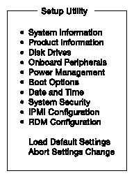
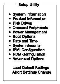
Figure 3-2 shows the Advanced Setup Utility screen.
The screen shown in Figure 3-3 appears if you select System Information from the main menu.
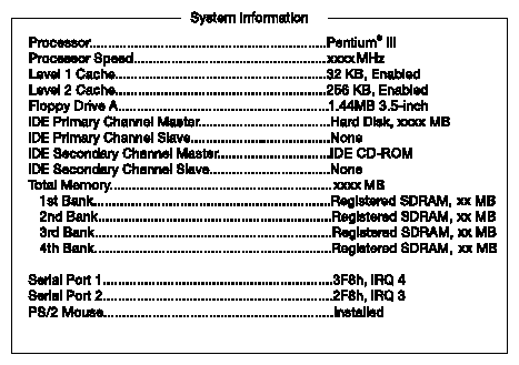
Table 3-1 describes the System Information parameters.
Table 3-1. System Information Parameters
Parameter | Description |
|---|---|
Processor | Type of processors currently installed in your system. |
Processor speed | Clock speed of the processors currently installed in your system. |
Level 1 cache size | Total amount of first-level cache (high-speed memory integrated into the CPU). |
Level 2 cache size | Total amount of second-level cache (a larger block of memory, also integrated into the CPU). |
Floppy drive A and B | System's current diskette drive A and B settings. |
IDE primary channel master | Current configuration of the IDE device connected to the master port of the primary IDE channel. |
IDE primary channel slave | Current configuration of the IDE device connected to the slave port of the primary IDE channel. |
IDE secondary channel master | Current configuration of the IDE device connected to the master port of the secondary IDE channel. |
IDE secondary channel slave | Current configuration of the IDE device connected to the slave port of the secondary IDE channel. |
Total memory | Total amount of onboard main memory. The memory size is automatically detected by BIOS during the POST. If you install additional memory, the system automatically adjusts this parameter to display the new memory size. |
1st/2nd/3rd/4th bank | Type and size of DRAM installed in DIMM sockets 1, 2, 3, and 4 respectively. The None setting indicates that there is no DRAM installed. |
Serial port 1 | Serial port 1 address and IRQ setting. |
Serial port 2 | Serial port 2 address and IRQ setting. |
PS/2 mouse | Pointing device installation settings. Displays None if no pointing device is installed. |
The Product Information screen contains the general data about the system, such as the product name, serial number, BIOS version, etc. This information is necessary for troubleshooting (and may be required when asking for technical support).
Figure 3-4 shows the Product Information screen.
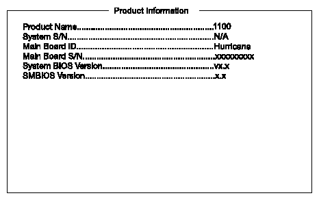
Table 3-2 describes the Product Information parameters.
Table 3-2. Product Information Parameters
Parameter | Description |
|---|---|
Product name | Official name of the system |
System S/N | System's serial number |
Main board ID | Identification number of the main board |
Main board S/N | Serial number of the main board |
System BIOS version | Version of the BIOS utility |
SMBIOS version | Version of the SMBIOS |
Select Disk Drives to input configuration values for floppy disk drives and IDE disk drives.
Figure 3-5 shows the Disk Drives screen.
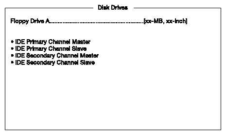
Table 3-3 describes the Disk Drives parameters. Settings in boldface are the default and suggested parameter settings.
Table 3-3. Disk Drives Parameter
Parameter | Description | Option |
|---|---|---|
Floppy drive A and B | Selects the floppy disk drive type | 1.44 MB, 3.5-inch None 360 KB, 5.25-inch 1.2 MB, 5.25-inch 720 KB, 3.5-inch 2.88 MB, 3.5-inch |
The screen shown in Figure 3-6 appears if you select the IDE Primary Channel Master parameter.

| Note: A parameter with an asterisk (*) indicates that the parameter appears only when you are in the Advanced Level. See “Entering Setup” for information about how to view the Advanced Level. |
Table 3-4 describes the IDE Drive parameters. Settings in boldface are the default and suggested parameter settings.
Table 3-4. IDE Drive Parameters
Parameter | Description | Option |
|---|---|---|
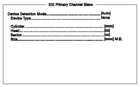
Device detection mode | Lets you specify the type of hard disk installed in your system. If you want BIOS to automatically configure your hard disk, select Auto. If you know your hard disk type, you can enter the setting manually. | Auto User None |
Device type | Indicates a hard disk type device. |
|
Cylinder | Specifies the number of cylinders of your hard disk, and is automatically set depending on your Type parameter setting. | User input |
Head | Specifies the number of heads of your hard disk, and is automatically set depending on your Type parameter setting. | User input |
Sector | Specifies the number of sectors of your hard disk, and is automatically set depending on your Type parameter setting. | User input |
Size | Specifies the size of your hard disk, in MB. | User input |
Hard disk LBA mode | This enhanced IDE feature allows the system to use a hard disk with a capacity of more than 528 MB. This is made possible through Logical Block Address (LBA) mode translation. LBA is now a standard feature of current IDE hard disks because it can support capacities larger than 528 MB. Note that if your HDD is formatted with LBA On, it cannot boot with LBA Off. | Auto Disabled |
Hard disk block mode | This function enhances disk performance depending on the hard disk in use. If you set this parameter to Auto, the BIOS utility automatically detects if the installed hard disk drive supports the lock mode function. If supported, it allows data transfer in blocks (multiple sectors) at a rate of 256 bytes per cycle. To disregard the feature, change the setting to Disabled. This parameter appears only when you are in the Advanced Level. | Auto Disabled |
Hard disk 32-bit access | Enabling this parameter improves system performance by allowing the use of the 32-bit hard disk access. This enhanced IDE feature works only with certain operating systems. This parameter appears only when you are in the Advanced Level. | Enabled Disabled |
Advanced PIO mode | When set to Auto, the BIOS utility automatically detects if the installed hard disk supports the function. If supported, it allows for faster data recovery and read/write timing that reduces hard disk activity time. This results in better hard disk performance. To disregard the feature, change the setting to Disabled. This parameter appears only when you are in the Advanced Level. | Auto |
DMA transfer mode | The Ultra DMA and Multi-DMA modes enhance hard disk performance by increasing the transfer rate. However, besides enabling these features in the BIOS Setup, both the Ultra DMA and Multi-DMA modes require the DMA driver to be loaded. This parameter appears only when you are in the Advanced Level. | Auto Multi word mode 0, 1, 2 Ultra Mode 0, 1, 2, 3, 4 Disabled |
The screen shown in Figure 3-7 appears if you select the IDE Primary Channel Slave parameter. The parameters are the same as those described in Table 3-4.
The IDE Secondary Channel Master and IDE Secondary Channel Slave screens are similar to those shown in Figures 3-6 and 3-7, and the parameters are the same as those described in Table 3-4.
The Onboard Peripherals screen in Figure 3-8 allows you to configure the onboard communication ports and the onboard devices.
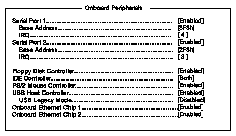
Table 3-5 describes the Onboard Peripherals parameters. Settings in boldface are the default and suggested parameter settings.
Table 3-5. Onboard Peripherals Parameters
Parameter | Description | Option |
|---|---|---|
Serial port 1 | Enables or disables serial port 1. | Enabled Disabled |
Base address | Sets the I/O base address of serial port 1. | 3F8h 2F8h 3E8h 2E8h |
IRQ | Sets the IRQ (interrupt request) channel of serial port 1. | 4 11 |
Serial port 2 | Enables or disables serial port 2. | Enabled Disabled |
Base address | Sets the I/O base address of serial port 2. | 2F8h 3F8h 3E8h 2E8h |
IRQ | Sets the IRQ (interrupt request) channel of serial port 2. | 3 10 |
Floppy disk controller | Enables or disables the onboard floppy disk controller. | Enabled Disabled |
IDE controller | Enables or disables the onboard IDE controller. | Both Primary Disabled |
PS/2 mouse controller | Enables or disables the onboard PS/2 mouse controller. | Enabled Disabled |
USB host controller | Enables or disables the onboard USB controller. | Enabled Disabled |
USB legacy mode | When enabled, allows you to use a USB keyboard in DOS. | Disabled Enabled |
Onboard Ethernet chip 1 | Enables or disables the first onboard network feature. | Enabled Disabled |
Onboard Ethernet chip 2 | Enables or disables the second onboard network feature. | Enabled Disabled |
The Power Management screen allows you to configure the system power management features. Figure 3-9 shows the Power Management parameters and their default settings.
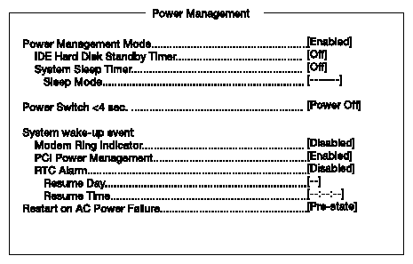
Table 3-6 describes the Power Management parameters. Settings in boldface are the default and suggested parameter settings.
Table 3-6. Power Management Parameters
Parameter | Description | Option |
|---|---|---|
Power management mode | Allows you to reduce power consumption. When this parameter is set to Enabled, you can configure the IDE hard disk and system timers. Setting it to Disabled deactivates the power-management feature and its timers. | Enabled Disabled |
IDE hard disk standby timer | Allows the hard disk to enter standby mode after inactivity of 1 to 15 minutes, depending on your setting. When you access the hard disk again, allow 3 to 5 seconds (depending on the hard disk) for the disk to return to normal speed. Set this parameter to Off if your hard disk does not support this function. | Off 1 - 15 minutes |
System sleep timer | This parameter sets the system to the lowest power-saving mode after a specified period of inactivity. Any keyboard or mouse action or any activity detected from the IRQ channels resumes system operation. | Off 2 - 120 minutes |
Sleep mode | Lets you specify the power-saving mode that the system will enter after a specified period of inactivity. This parameter becomes configurable only if the system sleep timer is on. Any keyboard or mouse action, or any enabled monitored activities occurring through the IRQ channels, resume system operation. | Standby Suspend |
Power switch < 4 sec. | When set to Power Off, the system automatically turns off when the power switch is pressed for fewer than 4 seconds. When set to Suspend, the system enters the suspend mode when the power switch is pressed for fewer than 4 seconds. | Power off Suspend |
System wake-up event | The system wake-up event allows the system to resume operation when the modem ring indicator is enabled. |
|
Modem ring indicator | When set to Enabled, any fax/modem activity wakes up the system from suspend mode. | Disabled Enabled |
PCI power management | Enables or disables the PCI power management function. | Enabled Disabled |
RTC alarm | Allows you to set a certain time on a certain day to wake up your system from suspend mode. | Disabled Enabled |
Resume day | If RTC alarm is enabled, the system will resume operation on the day indicated here. | User input |
Resume time | If RTC alarm is enabled, the system will resume operation at the time indicated here. | User input |
Restart on AC power failure | Reboots the system when a power failure occurs. If disabled, the system does not automatically reboot from a power failure. | Pre-state Enabled Disabled |
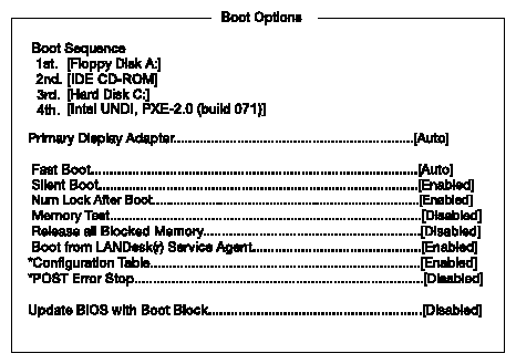
The Boot Options selection allows you to specify your preferred settings for bootup. The screen shown in Figure 3-10 appears if you select Boot Options from the main menu.
| Note: A parameter with an asterisk (*) indicates that the parameter appears only when you are in the Advanced Level. See “Entering Setup” for information about how to view the Advanced Level. |
Table 3-7 describes the Boot Options parameters. Settings in boldface are the default and suggested parameter settings.
Table 3-7. Boot Options Parameters
Parameter | Description | Option |
|---|---|---|
Boot sequence | This parameter allows you to specify the boot search sequence during POST. 1st. The system checks this drive first. 2nd. If the system is unable to boot from the 1st drive, it tries this drive. 3rd. If the system is unable to boot from the 1st and 2nd drives, it next tries this drive. 4th. If the system is unable to boot from the 1st, 2nd, and 3rd drives, it next tries this drive. BIOS will display an error message if all of the drives specified are not bootable. |
|
Primary display adapter | Lets you activate the onboard video controller as your primary display adapter, or automatically disable it if BIOS detects that a video card is installed in your system. | Onboard Auto |
Fast boot | Allows the system to boot faster by skipping some POST routines. | Disabled Auto |
Silent boot | Enables or disables the Silent boot function. When set to Enabled, BIOS is in graphical mode and displays only an identification logo during POST and while booting. After booting, the screen displays the operating system prompt (such as DOS) or logo (such as Windows NT). If any error occurs while booting, the system automatically switches to the text mode. Even if your setting is Enabled, you may also switch to the text mode while booting by pressing the Delete key when you see the “Press DELETE key to enter Setup” message on the screen. When set to Disabled, BIOS is in the conventional text mode in which you see the system initialization details on the screen. | Enabled Disabled |
Num Lock after boot | Activates the Num Lock function upon booting. | Enabled Disabled |
Memory test | When set to Enabled, this parameter allows the system to perform a RAM test during the POST routine. When set to Disabled, the system detects only the memory size and bypasses the test routine. | Disabled Enabled |
Release all blocked memory | When set to Enabled, this parameter allows the system to bypass testing any defective memory banks detected earlier. | Disabled Enabled |
Boot from LANDesk service agent | When set to Enabled, the system boots from a LANDesk service agent network instead of your desktop system. The LANDesk service agent is IEEE standards-based code that intervenes in the boot process. See your LANDesk manual for more information. When set to Disabled, the system boots from the drive specified in the Boot sequence parameter. | Enabled Disabled |
Configuration table | Displays preboot system configuration table when enabled. | Enabled Disabled |
Post error stop | When enabled, the system automatically stops when an error occurs during POST. Press F1 to continue. If disabled, the system does not stop even when an error occurs during the POST. | Disabled Enabled |
Update BIOS with boot block | When enabled, it automatically flashes (i.e., reprograms) the BIOS file from the hard disk drive if the system fails to boot. | Disabled Enabled |
The real-time clock keeps the system date and time. After setting the date and time, you do not need to enter them every time you turn on the system. As long as the internal battery remains good (approximately seven years) and connected, the clock continues to keep the date and time accurately even when the system power is off. Figure 3-11 shows the Date and Time screens.
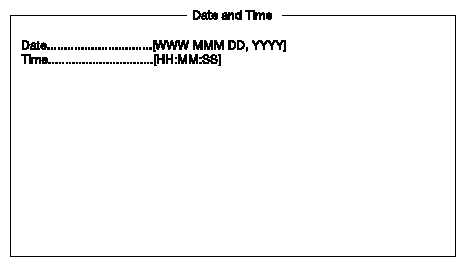
Table 3-8 describes the Date and Time parameters.
Table 3-8. Date and Time Parameters
Parameter | Description |
|---|---|
Date | Sets the date following the weekday-month-day-year format. Valid values for weekday, month, day, and year are: Weekday: Sun, Mon, Tue, Wed, Thu, Fri, Sat Month: Jan, Feb, Mar, Apr, May, Jun, Jul, Aug, Sep, Oct, Nov, Dec Day: 1 to 31 Year: 1980 to 2079 |
Time | Sets the time following the hour-minute-second format. Valid values for hour, minute, and second are: Hour: 00 to 23 Minute: 00 to 59 Second: 00 to 59 |
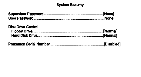
The Setup program has a number of security features to prevent unauthorized access to the system and its data. Figure 3-12 shows the screen that appears if you select System Security from the Setup Utility screen.
The supervisor password prevents unauthorized access to the BIOS utility.
| Note: The supervisor password should be modified only by trained service personnel, or by a system administrator. |
To set or change a password, follow these steps:
Make sure that jumper JP8 is set to 1-2 (bypass password). Changing the jumper setting requires that the chassis be opened. This task should therefore be performed only by trained service personnel, and is detailed in the SGI 1100 Server Maintenance and Upgrades Guide (007-4047-001).
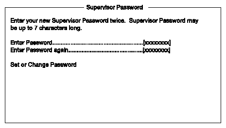
Note: You cannot enter the BIOS utility if a Setup password does not exist and jumper JP8 is set to 2-3 (password check enabled). By default, jumper JP8 is set to 1-2 (bypass password). Enable the Supervisor Password parameter in the System Security menu by pressing the left or right arrow keys. The Supervisor Password window shown in Figure 3-13 appears.
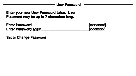
Type a password in the Enter Password field. The password may consist of as many as seven characters.
Press the Enter key. Retype your password in the Enter Password field to verify your first entry.
Highlight Set or Change Password and press the Enter key.
Press the Esc key to return to the System Security menu and then press the Esc key again to exit Setup. The Exit Setup screen, shown in Figure 3-14, appears.
Select Yes to save your settings and exit the Setup utility. Your password will be saved to CMOS.

For the password to take effect, jumper JP8 must be set to 2-3 (check password). Changing the jumper setting requires that the chassis be opened. This task should therefore be performed only by trained service personnel, and is detailed in the SGI 1100 Server Maintenance and Upgrades Guide (007-4047-001).
The next time you want to enter the BIOS utility, you must key in your supervisor password.
To remove your supervisor password, follow these steps:
Disable the Supervisor Password parameter in the System Security menu by pressing the left or right arrow key to select None.
Press the Esc key to return to the System Security menu and then press the Esc key again to exit Setup. The Exit Setup screen, shown in Figure 3-15, appears.
Select Yes to save your settings and exit Setup. Your previous password will be removed from CMOS.
Note: When removing the supervisor password, it is important that jumper JP8 ne set to 1-2 (bypass password). This is because you cannot access Setup if a supervisor password does not exist and jumper JP8 is set to 2-3 (check password). Changing the jumper setting should be performed only by trained service personnel.
If you forget your supervisor password, the password security feature can be bypassed by changing the setting of jumper JP8 to 1-2 (bypass password). Changing the jumper setting requires that the chassis be opened. This task should therefore be performed only by trained service personnel, and is detailed in the SGI 1100 Server Maintenance and Upgrades Guide (007-4047-001).
The User Password secures your system against unauthorized use. Once you set this password, you have to type it whenever you boot the system. To set this password, enter the Setup utility, select System Security, and then highlight the User Password parameter. See Figure 3-16, and follow the same procedure as for setting the “Supervisor Password”.
| Note: The user password should be modified only by trained service personnel, or by a system administrator. |
| Note: Jumper JP8 must be set to 2-3 to enable the user password. Changing the jumper setting requires that the chassis be opened. This task should therefore be performed only by trained service personnel, and is detailed in the SGI 1100 Server Maintenance and Upgrades Guide (007-4047-001). |
The Disk Drive Control features allow you to control the floppy drive or the hard disk drive boot function to prevent loading operating systems or other programs from a certain drive while the other drives are operational (under DOS mode only).
To change the Disk Drive Control settings, highlight the Floppy Drive or the Hard Disk Drive parameter in the System Security menu. Figure 3-17 shows the System Security screen. Press the left or right arrow keys to select one of the three settings described in Table 3-9.
Table 3-9 describes the Disk Drive Control settings.
Setting | Description |
|---|---|
Normal | Floppy drive or hard disk drive functions normally. |
Write protect all sectors | Disables the write function on all sectors. |
Write protect boot sector | Disables the write function only on the boot sector. |
The Pentium III processor incorporates an individual serial number in each chip that can identify individual CPUs. When enabled, CPUs can be identified by processor serial number. Disable this parameter to deactivate this feature.
To enable or disable the Processor Serial Number parameter, highlight it in the System Security menu. Figure 3-17 shows the System Security screen. Press the left or right arrow key to select the desired setting.
The system event log enables you to record and monitor events that occur in your system, such as system temperature changes, fan stops, and others. This feature also allows you to specify the appropriate settings for your system's event handling.
Figure 3-18 shows the IPMI Configuration screen.
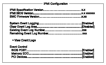
Table 3-10 describes the IPMI configuration parameters. Settings in boldface are the default and suggested parameter settings.
Table 3-10. IPMI Configuration Parameters
Parameter | Description | Option |
|---|---|---|
IPMI specification version | Specifies the version of Intelligent Platform Management Interface (IPMI). |
|
IPMI BIOS version | Shows the version of IPMI BIOS. |
|
Specifies the version of BaseBoard Management Controller (BMC) firmware. |
| |
System event logging | Enables or disables the event logging function of your system. | Enabled Disabled |
Clear event log area | Clears the event log whenever the event log area is full. | Disabled Enabled |
Existing event log number | Number of events currently located in the event log area. |
|
Remaining event log number | Number of spaces that are still available for logging system events. |
|
View event logs | Opens the system event log file for viewing. |
|
Event control |
|
|
BIOS POST | BIOS checks for bad processors and memory modules during POST. When this parameter is enabled, BIOS will stop POST operation whenever it finds a bad processor or memory. Otherwise, if disabled, the system continues running. | Enabled Disabled |
Memory ECC | ECC or error-correcting code tests the accuracy of data as it passes in and out of memory. This parameter enables or disables the monitoring of this function. | Enabled Disabled |
PCI devices | PCI or Peripheral Component Interconnect is a 32-bit bus that supports a 64-bit extension for new processors, such as the Pentium III. It can run at clock speeds of 33 or 66 MHz. This parameter monitors the activity of this bus when set to Enabled. | Enabled Disabled |
Figure 3-19 shows the RDM Configuration screen.
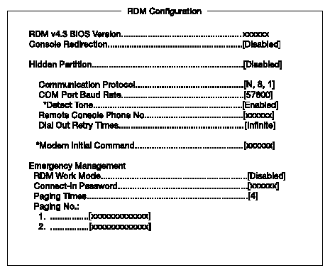
| Note: A parameter with an asterisk (*) indicates that the parameter appears only when you are in the Advanced Level. See “Entering Setup” for information about how to view the Advanced Level. |
Table 3-11 describes the RDM Configuration parameters. Settings in boldface are the default and suggested parameter settings.
Table 3-11. RDM Configuration Parameters
Parameter | Description | Option |
|---|---|---|
RDM 4.3 BIOS version | Shows the version number of the RDM BIOS. |
|
Console redirection | This parameter lets you enable or disable the connection to the RDM manager station. If enabled and conditions are met, the RDM-enabled server automatically dials the RDM manager station using the phone number specified in the remote Console phone no. parameter when the server reboots. Once the connection is established, both the RDM server and RDM manager station display the same screen that enables the RDM manager station to function the same as the server console. Setting this to Disabled deactivates the RDM manager station. | Disabled Enabled |
Hidden partition | If you want the hidden partition to become accessible, set this parameter to Enabled. When enabled, the server boots to the hidden partition. | Disabled Enabled |
Communication protocol | This parameter specifies the parity, stop bits, and data length for the COM port to be used for the RDM connection. This is fixed at N (none), 8, or 1 and is non-configurable. | N, 8, or 1 |
COM port baud rate | This parameter lets you set the transfer rate of the COM port for the RDM connection. The parameter setting depends on your modem specification; therefore, before you change the setting of this parameter, check your modem user guide. | 9600 57600 |
*Detect tone | When enabled, RDM checks for the existence of the telephone tone before it dials out. When disabled, RDM proceeds with the dialing process without checking for the telephone tone. This parameter appears only when you are in the Advanced Level. | Enabled Disabled |
Remote console phone no. | This parameter allows you to set the phone number of the RDM manager station that the RDM module must dial once RDM is activated and the remote console is enabled. To set it, simply highlight the parameter and enter the remote console phone number. If the remote console phone number is using an extension line, then you must enter six commas (,) after the phone number and before the extension number, if any. When entering the extension number, we recommend that you insert a comma after each number. The commas specify delay. If this parameter is left blank, the Remote Console calling function is disregarded. | User input |
Dial out retry times | This parameter lets you specify the maximum number of times the RDM server must retry to connect to the RDM manager station once the server fails and RDM is activated. If the server has completed the specified number of tries and the connection still fails, the server bypasses RDM and goes into normal mode. | 2 4 8 Infinite |
*Modem initial command | Some modems require specific commands for initialization. This parameter allows you to specify the required command to enable your system to support special types of modems. If you do not specify any command, BIOS uses the default method to initialize the modem. Note: Specify an initialization command only when you receive a Modem Initial Command Fail error message. Otherwise, leave this parameter blank. This parameter appears only when you are in the Advanced Level. | User input |
Emergency management |
|
| Note: To avoid damaging the system, do not change any settings in the Advanced Options screen if you are not a qualified technician. |
Figure 3-20 shows the Advanced Options parameters.
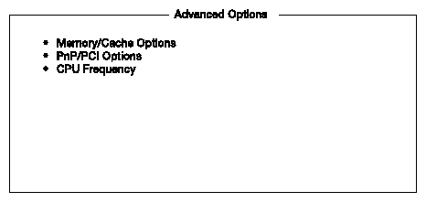
The Memory/Cache Options screen in Figure 3-21 allows you to configure the advanced system memory functions.
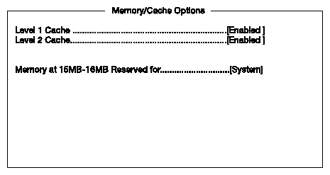
Table 3-12 describes the Memory/Cache Options parameters. Settings in boldface are the default and suggested parameter settings.
Table 3-12. Memory/Cache Options Parameters
Parameter | Description | Option |
|---|---|---|
Level 1 cache | Enables or disables the first-level or internal memory, that is, the memory integrated into the CPU. | Enabled Disabled |
Level 2 cache | Enables or disables the second-level cache memory which is incorporated in the CPU module. | Enabled Disabled |
Memory at 15 MB - 16 MB reserved for | To prevent memory address conflicts between the system and expansion boards, reserve this memory range for the use of either the system or an expansion board. | System Add-on card |
The PnP/PCI Options screen in Figure 3-22 allows you to specify the settings for your PCI devices.

Table 3-13 describes the PnP/PCI Options parameters. Settings in boldface are the default and suggested parameter settings
Table 3-13. PnP/PCI Options Parameters
Parameter | Description | Option |
|---|---|---|
PCI IRQ setting | Select Auto to let BIOS automatically configure the plug-and-play (PnP) devices installed on your system; otherwise, select Manual. Note: See your manual for technical information about the PCI card. | Auto Manual |
PCI slot 1 | When you set the PCI IRQ setting parameter to Auto, this parameter specifies the auto-assigned interrupt for the PCI device. If you set the PCI IRQ setting parameter to Manual, you need to specify the interrupt that you want to assign for the PCI device installed in your system. | User input |
Onboard VGA | Allows you to manually assign the interrupt for the onboard VGA when the PCI IRQ setting parameter is set to Manual. This parameter is grayed and not user-configurable when the PCI IRQ setting is set to Auto. | User input |
Onboard LAN | When you set the PCI IRQ setting parameter to Auto, this parameter specifies the auto-assigned interrupt for the onboard LAN. If you set the PCI IRQ setting parameter to Manual, you need to specify the interrupt that you want to assign for the onboard LAN installed in your system. | User input |
USB host controller | Allows you to manually assign the interrupt for the USB host controller when the PCI IRQ setting parameter is set to Manual. This parameter is grayed and not user-configurable when the PCI IRQ setting is set to Auto. | User input |
PCI IRQ sharing | Setting this parameter to Yes allows you to assign the same IRQ to two different devices. To disable the feature, select No. Note: If no IRQs are available to assign for the remaining device function, it is recommended that you enable this parameter. | Yes No |
VGA palette snoop | This parameter permits you to use the palette snooping feature if you installed more than one VGA card in the system. The VGA palette snoop function allows the control palette register (CPR) to manage and update the VGA RAMDAC (Digital Analog Converter, a color data storage) of each VGA card installed in the system. The snooping process lets the CPR send a signal to all the VGA cards so that they can update their individual RAMDACs. The signal goes through the cards continuously until all RAMDAC data has been updated. This allows the display of multiple images on the screen. Note: Some VGA cards have required settings for this feature. Check your VGA card manual before setting this parameter. | Disabled Enabled |
Plug and play OS | When this parameter is set to Yes, BIOS initializes only PnP boot devices such as SCSI cards. When set to No, BIOS initializes all PnP boot and non-boot devices such as sound cards. Note: Set this parameter to Yes only if you are using a plug-and-play-aware operating system, such as Windows 2000. | Yes No |
Reset resource assignments | Set this parameter to Yes to avoid IRQ conflicts when installing non-PnP or PnP ISA cards. This clears all resource assignments and allows BIOS to reassign resources to all installed PnP devices the next time the system boots. After clearing the resource data, the parameter resets to No. | No Yes |
The CPU Frequency screen in Figure 3-23 displays your CPU's speed and bus frequency.
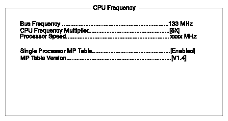
Table 3-14 describes the CPU Frequency parameters. Settings in boldface are the default and suggested parameter settings.
Table 3-14. CPU Frequency Parameters
Parameter | Description | Option |
|---|---|---|
Bus frequency | The bus frequency refers to the speed by which data is transferred between internal computer components and the CPU (sometimes called Front Side Bus, or FSB). Clock speeds are expressed in megahertz (MHz), with 1 MHz being equal to 1 million cycles per second. A fast bus allows data to be transferred faster, which makes applications run faster. | Options |
CPU frequency multiple | This column shows the CPU core/bus ratio of your system. This ratio determines the clock speed of the CPU core as a multiple of the bus speed. System BIOS automatically detects CPU frequency multiple. | 3X, 3.5X, 4X, 4.5X, 5X, 5.5X, 6X, 6.5X, 7X, 7.5X, 8X |
Processor speed | The processor speed is the bus frequency multiplied by the CPU frequency multiple, and is set automatically by BIOS. The faster the clock, the more instructions the CPU can execute per second. When two CPUs are installed, they will both run at the same frequency. |
|
Single processor MP table | Enabling this parameter allows BIOS to create a multiprocessor (MP) table for Windows NT use. In a single-processor system running Windows NT, you may disable this parameter to enhance system performance. If you install another CPU for a dual system, enable this parameter and then re-install Windows NT. In cases when this parameter is enabled before installing Windows NT in a single-processor system, you may upgrade to a multiprocessor system without reinstalling Windows NT. | Enabled Disabled |
MP table version | Version number of the MP table. |
|
Use this option to load the default settings for the optimized system configuration. When you load the default settings, some of the parameters are grayed-out with their fixed settings. These grayed parameters are not user-configurable.
The dialog box in Figure 3-24 appears when you select Load Default Settings from the main menu.

Select Yes to load the default settings.
Select No to ignore the message and return to the BIOS utility.
Use this option to disregard your changes to the BIOS and reload your previous settings. The dialog box in Figure 3-25 appears when you select Abort Settings Change from the main menu.

Select Yes to disregard your changes and reload your previous settings. After reload, the main menu appears on the screen.
Select No to ignore the message and return to the BIOS utility.
Examine the system configuration values. When you are satisfied that all the values are correct, write them down. Store the recorded values in a safe place. In the future, if the battery loses power or the CMOS chip is damaged, you will know what values to enter when you rerun Setup.
Press the Esc key to exit Setup. The dialog box shown in Figure 3-26 appears.

Use the arrow keys to select your response. Press the Enter key.
If you made any changes to the Setup utility, the dialog box shown in Figure 3-27 is displayed.
Use the arrow keys to select your response. Select Yes to save the changes in CMOS. Select No to retain the previous configuration values. Press the Enter key to exit.