The SGI 1100 is a 1U, high-density, rackmountable, PCI bus-based dual-processor system built on an extended ATX baseboard. The system is fully compatible with Linux, Windows NT 4.0 and Windows 2000 Advanced Server operating systems.
This chapter describes the main features of the SGI 1100 server, and provides setup information in the following sections:
Remove the server from the packaging container and check that the following items are included:
SGI 1100 system
SGI 1100 Server Quick Start Guide
SGI 1100 Server Documentation CD
Resource CD (contains device drivers)
Rack mount kit
Inspect the above items for evidence of mishandling during transit. If the contents appear damaged, file a damage claim with the carrier immediately.
Save the boxes and packing materials for future use.
The SGI 1100 server is designed to be mounted in a standard 19-inch rack. For instructions on mounting the SGI 1100 server in a 19-inch rack, see Chapter 2, “Rack Mounting Instructions”.
Table 1-1 shows the physical and environmental specifications for the SGI 1100 server system.
Table 1-1. SGI 1100 Server Physical and Environmental Specifications
Height | 1u (1.75 in., 4.45 cm) |
Width | 19.0 in. (48.25 cm) |
Depth | 21.2 in. (53.85 cm) |
Weight | 24.2 lbs. (11 kg), maximum configuration |
Temperature | +5 °C (41 °F) to +35 °C (+95 °F) (operating) |
Humidity | 20% - 80% RH, non-condensing |
Vibration: Operating (unpacked) Non-operating (packed) |
5 - 16.2 Hz: 0.38 mm (peak to peak) 5 - 27.1 Hz: 0.60 G |
The server power supply is rated for a maximum of 200W DC output. Maximum AC input power consumption is approximately 307W. Consider the following:
Using 110V AC power, a fully loaded system can consume up to 2.80A.
Using 220V AC power, a fully loaded system can consume up to 1.40A.
The deployment of ultra-dense 1U servers represents a significant power requirement. A simple formula to calculate server power requirements for an installation is:
(Number of servers) x (307W) = maximum power requirements for servers
The server has the following cooling systems:
Fan wall with three internal swappable fans
Fan-sink for each of two CPUs
One internal power supply fan
Two rear blowers
A fully configured SGI 1100 server under maximum workload can produce approximately 1047 Btu/hr. Air temperature measurements around the server may vary as much as 25 ˚C (45 ˚F) from front to back. Deployment of multiple ultra-dense servers will produce a significant amount of heat. For example, 36 servers under maximum workload can generate as much as 37,692 Btu/hr.
The server operates reliably within normal office environments. Select a site that meets these criteria:
Near a properly earthed, grounded, three-pronged power outlet, as follows:
In the U.S. and Canada: a NEMA 5-15R outlet for 100-120 V or a NEMA 6-15R outlet for 200-240 V.
In other geographic areas: a properly earthed, grounded outlet in accordance with the local electrical authorities and electrical codes of the region.
Clean and relatively free of excess dust.
Well-ventilated and away from sources of heat, with the ventilation openings on the server kept free of obstructions.
Away from sources of vibration or physical shock.
Isolated from strong electromagnetic fields and line noise caused by electrical devices such as elevators, copy machines, air conditioners, large fans, large electric motors, radio and TV transmitters, and high-frequency security devices.
Access space provided so the server power cords can be unplugged from the power supply or the wall outlet. This is the only way to remove AC power from the server.
Clearance provided for cooling and airflow.

Caution: In regions that are susceptible to electrical storms, it is recommended that you plug your system into a surge suppressor and disconnect any telecommunication lines during electrical storms.
This section describes the front controls and indicators of the SGI 1100 server as shown in Figure 1-1.
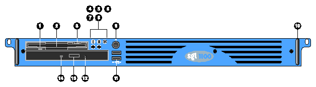
Table 1-2 describes the front controls and indicators that are indicated in Figure 1-1.
Table 1-2. Front Controls and Indicators
No. | Item |
|---|---|
1 | Slim-type floppy disk drive LED |
2 | Slim-type floppy disk drive |
3 | Slim-type floppy disk drive eject button |
4 | Event LED |
5 | Hard disk drive access LED |
6 | Power LED |
7 | LAN 2 access LED |
8 | LAN 1 access LED |
9 | Power button |
10 | Metal handle |
11 | USB ports (2 ports) |
12 | Slim-type CD-ROM drive emergency eject hole |
13 | Slim-type CD-ROM drive eject button |
14 | Slim-type CD-ROM drive LED |
The general event LED indicates the following occurrences:
Temperature, voltage, system fan, redundant power supply, or fuse events.
CPU IERR and Thermtrip error.
System fan or power supply unplug.
Uncorrectable memory error (multiple ECC errors).
PCI PERR or SERR error.
If all of the preceding events recover, the Baseboard Management Controller (BMC) should turn off the LED.
 | Note: The BMC will not turn on the general event LED for BIOS POST, PCI hot plug, and correctable memory error events. |
This section describes the rear panel I/O ports and other features as shown in Figure 1-2.

Table 1-3 describes the rear panel I/O ports and features that are indicated in Figure 1-2.
Table 1-3. Rear Panel I/O Ports and Features
No. | Item |
|---|---|
1 | AC power input |
2 | Ventilation |
3 | Serial port 2 |
4 | PS/2 mouse port |
5 | Ventilation |
6 | Ventilation |
7 | Add-on card bracket |
8 | LAN 2 port (RJ-45) |
9 | LAN 1 port (RJ-45) |
10 | USB ports (2 ports) |
11 | VGA port |
12 | Serial port 1 |
13 | PS/2 keyboard port |
The SGI 1100 Server may be used with a VGA monitor, a keyboard (PS/2 or USB), and a mouse (PS/2 or USB). Once the system is configured, it may also be used with no console device.
The various connections are described in “Rear Panel I/O Ports and Features”.
After making sure that you have set up the system properly and connected all the required cables, you may now power on the system by pressing the power button.
The system will start and display a welcome message. After that, a series of power-on self-test (POST) messages appear. The POST messages indicate if the system is running well or not.
| Note: If the system does not turn on or boot after pressing the power button, see the next section for the possible causes of the boot failure. |
Aside from the self-test messages, you can determine if the system is in good condition by checking if the following occur:
Power indicator LED on the front bezel lights up (green).
Num Lock, Scroll Lock, and Caps Lock LED indicators on the keyboard flash briefly.
If the system does not boot after you have applied power, check the following factors that might have caused the boot failure.
The external power cable may be loosely connected.
Check the power cable connection from the power source to the power socket on the rear panel. Make sure that each cable is properly connected to each power supply.No power comes from the grounded power outlet.
Ask an electrician to check your power outlet.Note: If you have performed the preceding actions and the system still fails to boot, ask your dealer or a qualified technician for assistance.
IPMI is an open standard hardware manageability interface specification. It provides an architecture that defines how unique devices can all communicate with the CPU in a standard way.
With IPMI, the CPU only communicates one event to the IPMI event log. The CPU only “asks” what has changed since the last time it asked. Every device communicates directly, through IPMI, to the event log, which is used to record, in a consistent way, all status events for the unique device. This simplifies the agent-handling routine. The system only needs a single agent, and it does not need to be changed when you change from five devices to manage, for example, to six. And the system does not need to change the way the CPU checks the event log when a new device is added to the system; it always checks in the same way, whether there is one device or 100 devices. With IPMI, use of the CPU is minimized, so overall system performance improves.
The following are the four elements of IPMI, each of which is described in the sections that follow:
Intelligent Platform Management Interface
Intelligent Platform Management Bus
Intelligent Chassis Management Bus
Baseboard Management Controller
IPMI is the specification for the management controller command sets, including command sets for sensors, event logs, and sensor data record access. It is also the specification for the data formats, including sensor data records, event log entries, and FRU inventory information. IPMI is also the name used for the overall standardization effort.
IPMB is the I2C-based, multi-master bus used for intra-chassis communication with “satellite” management controllers. Here sensor devices and cards with IPMI bus access can be added to the IPMI standard.