This chapter includes the following sections:
This section introduces the following basic concepts and requirements of the Remote Volume Mirroring feature:
The Remote Volume Mirroring premium feature is used for online, real-time replication of data between storage arrays over a remote distance. In the event of a disaster or catastrophic failure at one storage array, you can promote a second storage array to take over responsibility for computing services.
This section introduces you to primary, secondary, and mirror repository volumes, and describes how they interact to replicate data between storage arrays using the Remote Volume Mirroring feature.
When you create a remote volume mirror, a mirrored volume pair is created and consists of a primary volume at a primary storage array and a secondary volume at a secondary storage array. A stan dar d volume may only be included in one mirrored volume pair. There can be up to 8 defined mirrors on a SGI TP9400 storage array and up to 32 defined mirrors on a SGI TP9500 storage array.
The primary volume is the volume that accepts host I/O and stores application data. When the mirror relationship is first created, data from the primary volume is copied in its entirety to the secondary volume. This process is known as a full synchronization and is directed by the controller owner of the primary volume. During a full synchronization, the primary volu me remains fully ac cessible for all normal I/O operations.
The controller owner of the primary volume initiates remote writes to the secondary volume to keep the data on the two volumes synchronized. Whenever the data on the primary volume and the secondary volume becomes unsynchronized, the controller owner of the primary volume initiates a full synchronization.
The secondary volume maintains a mirror (or copy) of the data on its associated primary volume. The controller ow ner of the secondary volume receives remote writes from the primary volume controller owner, but will not accept host read or write requests.
The secon dary volume remains unavailable to host applications while mirroring is underway. In the event of a disaster or catastrophic failure of the primary site, a role reversal can be performed to promote the secondary volume to a primary role. Hosts will then be able to access the newly promoted volume and business operations can continue.
Figure 3-1 shows the primary and secondary volumes displayed in the Array Management window for the primary storage array and the secondary storage array.
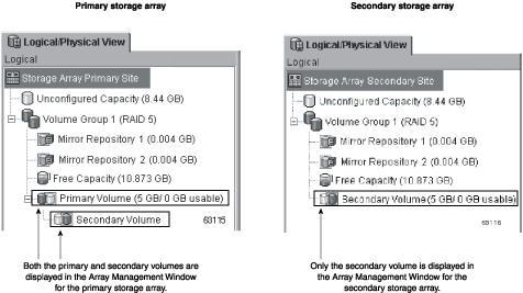
A mirror repository volume is a special volume in the storage array created as a resource for the controller owner of the primary volume in a Remote Volume Mirror. The controller stores mirroring information on this volume, including information about remote writes that are not yet complete. The controller can use this information to recover from contr oller resets and accidental powering-down of storage arrays.
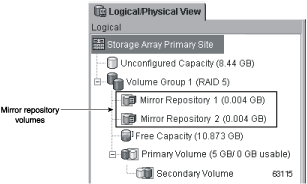
When you activate the Remote Volume Mirroring premium feature on the storage array, you create two mirror repository volumes, one for each controller in the storage array. An individual mirror repository volume is not needed for each Remote Volume Mirror.
When you create the mirror repository volumes, you specify the location of the volumes. You can either use existing free capacity or you can create a volume group for the volumes from unconfigured capacity and then specify the RAID level.
Figure 3-2 shows the mirror repository volumes displayed in the Array Management window for the primary storage array.
Because of the critical nature of the data being stored, the RA ID level of mirror repository volumes must not be RAID 0 (for data striping). The required size of each vol ume is 4 MB, or 8 MB total for both mirror repository volumes of a dual controller array.
Prior to creating a mirror relati onship, the Remote Volume Mirroring premium feature must be enabled on both the primary and secondary storage arrays. A secondary volume candidate must be created on the secondary site if one does not already exist and must be a standard volume of equal or greater capacity than the associated primary volume.
When secondary vol ume candidates are available, a mirror relationship can be established in the storage management software by identifying the storage array containing the primary volume and the storage array containing the secondary volume.
When the mirror relationship is first created, a full synchronization automatically occurs, with data from the primary volume copied in its entirety to the secondary volume. For more information on creating mirror relationships, see “Creating Mirror Relationships”.
Data replication between the primary volume and the secondary volume is managed by the controllers and is transparent to host machines and applications. This section describes how data is replicated between storage arrays participating in Remote Volume Mirroring and the actions taken by the controller owner of the primary volume if a link interruption occurs between storage arrays.
When the controller owner of the primary volume receives a write request from a host, the controller first logs information about the write to a mirror repository volume, then writes the data to the primary volume. The controller then initiates a remote write operation to copy the affected data blocks to the secondary volume at the secondary storage array.
After the host write request has been written to the primary volume and the data has been successfully copied to the secondary volume, the controller removes the log record on the mirror repository volume and sends an I/O completion indication back to the host system. See Figure 3-3 for a graphical representation of the data replication process.
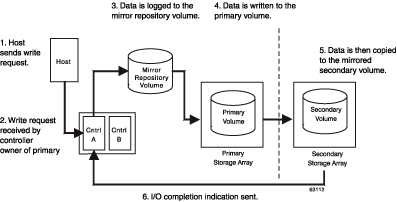
Because the controller does not send the I/O completion to the host until the data has been copied to both the primary and secondary volumes, this mirroring operation is called synchronous.
When a read request is received from a host system, the controller owner of the primary volume handles the request normally and no communication takes place between the primary and secondary storage arrays.
When processing write requests, the primary controller may be able to write to the primary volume, but a link interruption prevents communication with the remote secondary controller.
In this case, the remote write cannot complete to the secondary volume and the primary and secondary volumes are no longer correctly mirrored. The primary controller transitions the mirrored pair into an Unsynchronized status and sends an I/O completion to the primary host, as shown in Figure 3-4. The primary host can continue to write to the primary volume but remote writes will not take place.
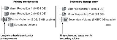
When connectivity is restored between the controller owner of the primary volume and the controller owner of the secondary volume, a full synchronization will automatically take place. The mirrored pair will then transition from an Unsynchronized status to a Synchronization-in-Progress status, as shown in Figure 3-5.
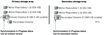
The primary controller will also mark the mirrored pair as Unsynchronized when a volume error on the secondary side prevents the remote write from completing. For example, an offline or a failed secondary volume can cause the Remote Volume Mirror to become Unsynchronized. When the volume error is corrected (the secondary volume is placed online or recovered to an Optimal status), then a full synchronization automatically begins, and the mirrored pair transitions to a Synchronization-in-Progress status.
For more information on Remote Volume Mirroring statuses, see “Using the Remote Volume Mirroring Premium Feature”.
The Remote Volume Mirroring feature requires a dedicated host port for mirroring data between storage arrays. This section describes the typical configurations used to connect storage arrays for Remote Volume Mirroring, controller ownership of volumes within storage arrays, the maximum storage array distance permitted, and some general performance considerations.
Once the Remote Volume Mirroring feature has been activated, one Fibre Channel host-side I/O port on each controller is solely dedicated to mirroring operations. For example, in the primary storage array, controller ports A2 and B2 are dedicated to mirroring operations. In the secondary storage array, controller ports A2 and B2 are also dedicated to mirroring operations.
Any host-initiat ed I/O operations will not be accepted by the dedicated port, and any requests received on this dedicated port will only be accepted from another controller participating in the mirror relationship.
Controller ports dedicated to Remote Volume Mirroring must be attached to a Fibre Channel fabric environment with support for the Directory Service and Name Service interfaces.
Three Fibre Channel fabric configurations are supported in this version of the storage management software. The level of redundancy available will depend on the type of configuration selected.
Highest Availability Campus Configuration – A fully redundant configuration, which consists of a primary storage array and a secondary storage array. For more information, see “Highest Availability Campus Configuration”.
Campus Configuration – A lower-cost configuration, which consists of a primary storage array and a secondary storage array. For more information, see “Campus Configuration”.
Intra-Site Configuration – Lowest-cost configuration, where the primary storage array and secondary storage array are located within the same site. For more information, see “Intra-Site Configuration”.
For instructions on how to configure storage arrays, see “Hardware and Software Installation”.
The controller owner of the primary volume will only attempt to communicate with its mirrored controller in the secondary storage array. As shown in Figure 3-6, Controller A in the primary storage array only attempts communication with Controller A in the secondary storage array.
The controller (A or B) that owns the primary volume determines the controller owner of the secondary volume. If the primary volume is owned by Controller A on the primary storage array, the secondary volume is therefore owned by Controller A on the secondary storage array. If primary Controller A cannot communicate with secondary Controller A, no controller ownership changes take place.
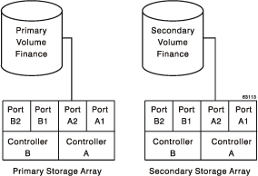
When an I/O path error causes a volume ownership change on the primary storage array, or if the storage administrator changes the controller owner of the primary volume, the next remote write processed will automatically trigger an ownership change on the secondary storage array.
As shown in Figure 3-7, if a primary volume is owned by Controller A and the controller owner is changed to Controller B, the next remote write will change the con troller owner of the secondary volume from Controller A to Controller B.
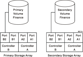
Because controller ownership changes on the secondary storage array are controlled by the primary controller, they do not require any special intervention and cannot be manually changed by the storage administrator.
The maximum distance permitted between storage arrays participating in a mirror relationship is governed by the distance limits of the Fibre Channel links. Using standard Single-Mode Fiber technology, a maximum link distance of 10 km between storage arrays can be achieved.
 | Note: Specialized third-party products allow for greater distances to be supported between storage arrays in a Fibre Channel environment. However, in this version of the storage management software, distances between storage arrays have been tested and verified up to 10 km. |
The following general performance considerations should be noted when creating Remote Volume Mirrors.
The controller owner of a primary volume performs a full synchronization in the background while processing local I/O writes to the primary volume and associated remote writes to the secondary volume. Because the full synchronization diverts controller processing resources from I/O activity, it can have a performance impact to the host application.
To reduce the performance impact, you can set the Synchronization Priority Level to determine how the controller owner will prioritize the full synchronization relative to other I/O activity. The following are some basic guidelines to setting the Synchronization Priority Level.
A full synchronization at the Lowest Synchronization Priority Level will take approximately eight times as long as a full synchronization at the Highest Synchronization Priority Level.
A full synchronization at the Low Synchronization Priority Level will take approximately six times as long as a full synchronization at the Highest Synchronization Priority Level.
A full synchronization at the Medium Synchronization Priority Level will take approximately three and a half times as long as a full synchronization at the Highest Synchronization Priority Level.
A full synchronization at the High Synchronization Priority Level will take approximately twice as long as a full synchronization at the Highest Synchronization Priority Level.
For more information on setting the Synchronization Priority Level, see “Using the Remote Volume Mirroring Premium Feature”.
When the mirrored volume pair is in a Synchronization-in-Progress status, all host write data is copied to the remote system in processing the I/O. Both controller I/O bandwidth and I/O latency can affect host write performance. Host read performance is not affected by the mirroring relationship.
The time that it takes for data to be copied from the primary volume to the secondary volume may impact overall performance and is primarily because of the delay and overhead of copying data to the Remote Volume Mirror. Some delay may also occur because of the limit to the number of simultaneous writes.
This section describes how the Remote Volume Mirroring premium feature can be used in conjunction with other premium features available in this version of the storage management software.
Storage Partitioning is a premium feature that enables hosts to share access to volumes in a storage array. A storage partition is created when you define a collection of hosts (a host group) or a single host and then define a volume-to-logical unit number (LUN) mapping. This mapping allows you to define what host group or host will have access to a particular volume in the storage array.
Figure 3-8 shows the Mappings View of the Array Management window, where Primary Volume Accounting has been included in a partition accessible by Host Group Campus East, and Secondary Volume Accounting 2 has been included in a partition accessible by Host Group Campus West.
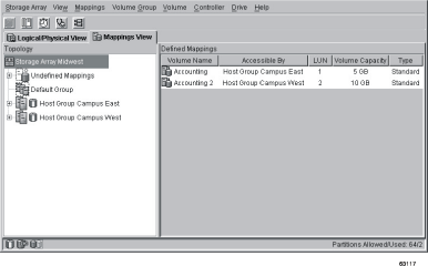
The storage partition definitions for the primary and secondary storage arrays are independent of each other. If these def initions are put in place while the volume is in a secondary role, it will reduce the administrative effort associated with site recovery if it becomes necessary to promote the volume to a primary role. For more information on defining storage partitions, see the Array Management window online help.
A snapcopy volume is a point-in-time image of a volume and is typically created so that an application, such as a backup application, can access the snapcopy volume and read the data while the base volume remains online and accessible to hosts.
The volume for which the point-in-time image is created is known as the base volume and must be a standard volume in the storage array. For the Remote Volume Mirroring feature, the base volume of a snapcopy volume is permitted to be a candidate for the primary volume in a mirror relationship. The snapcopy repository volume stores information about all data altered since the snapcopy was created. Figure 3-9 shows the primary volume (also the base volume for the snapcopy volume), the secondary volume, and the snapcopy volume in the Array Management window for the primary storage array.
| Note: The secondary volume of a mirror relationship cannot be a base volume with an associated snapcopy volume. |
Secondary v olumes are restricted from being the base volume for a snapcopy volume because any full synchronization process would fill the snapcopy repository volume, resulting in a failed snapcopy volume.
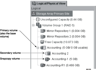
Snapcopy Volume Failure
In this version of the storage management software, snapcopy volumes based on the primary volume of a mirrored volume pair are permitted.
If a role reversal is performed and the primary volume is demoted to the secondary volume role, all snapcopy volumes associated with the demoted primary volume will be failed.
| Note: A secondary volume cannot be selected to be the base volume of a snapcopy volume. |
As shown in Figure 3-10, Primary Volume Accounting and Secondary Volume Accounting 2 are displayed in the Logical view of the Array Management window for the primary storage array. A snapcopy volume of Primary Volume Accounting has been created.
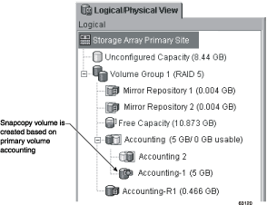
If a role reversal is performed, Primary Volume Accounting is demoted to a secondary role and the snapcopy volume fails, as shown in Figure 3-11. This is because the Secondary Volume Accounting 2 is now considered as the base volume of the snapcopy volume, which is not permitted.
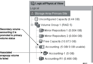
If a snapcopy volume fails as the result of a role reversal, you will need to perform another role reversal to promote the secondary volume back to a primary role. After the role reversal is complete, the snapcopy volume will return to an Optimal status. For more information, see “Troubleshooting”.
Using an operating system-specific defragment utility to perform a defragment operation on a base volume with an associated snapshot volume will cause a copy-on-write of every data block in the base volume. This can cause the snapshot repository to fill before the defragment operation is completed. As a result, the snapshot volume will fail or host writes will fail to the base volume, depending on the Snapshot Volume Full condition that was originally set for the snapshot volume.
To prevent this from occurring, ensure that the snapshot repository volume's capacity is set to at least 105% of the size of the base volume before using a defragment utility. This is the minimum size needed to support a copy-on-write of every data block in the base volume, which will occur as a result of a defragment operation.
This section describes the minimum hardware requirements for the Remote Volume Mirroring feature. A list of the certified host bus adapters for each operating system is provided.
The minimum software requirements for the Remote Volume Mirroring feature are provided, together with the host operating systems certified for use with this version of the storage management software.
The following are the minimum hardw are requirements needed when configuring your system to use the Remote Volume Mirroring premium feature. The list includes components that are supplementary to the standard required for a basic storage array environment as described in the SGI TP9500 RAID Installation and Upgrade Guide.
Minimum of two multi-ported storage arrays
RAID controllers with two or more host ports
Switches – These devices are used to connect multiple hosts with multiple storage arrays in a controlled environment. Multiple switches can be connected over a distance up to 10 km (6.25 miles) to create a fabric environment.
The certified switches for use with the Remote Volume Mirroring feature are as follows.
Brocade Silkworm 2400 – 8-port, 1 Gigabit/sec (Highest Availability Campus Configuration and Intra-Site Configuration only)
Brocade Silkworm 2800 – 16-port, 1 Gigabit/sec
Brocade Silkworm 3800 – 16-port, 2 Gigabit/sec
Brocade Silkworm 3200 – 8-port, 2 Gigabit/sec
Short or Medium Range Fibre Channel Cables – To connect the hosts and storage arrays to the switches.
Long Range Fibre Channel Cables (Campus Configurations only) – These cables are up to 10 km (6.25 miles) in length. These are used to connect Fibre Channel switches to complete long distance fabrics.
The following are the minimum software requirements needed when configuring your system to use the Remote Volume Mirroring premium feature.
Certified Host Operating Systems
Hosts accessing mirrored volumes should be running one of the following certified operating systems when using the Remote Volume Mirroring feature:
Windows NT 4.0 SP 6a Server Edition
Windows 2000 SP 2
Windows 98
Solaris 2.6, 2.7 (Solaris 7), 2.8 (Solaris 8)
HP-UX 11.0 or later
Linux (Red Hat 6.x)
Netware 5.1
IRIX 6.5.14 or later
AIX 4.3.3 or later
This section describes the key configurations supported for Remote Volume Mirroring in this version of the storage management software. The level of redundancy will be determined by the type of configuration chosen.
The Highest Availability Campus Configuration is a fully redundant configuration, and consists of two storage arrays and four switches connected using a Fibre Channel fabric as shown in Figure 3-12. The primary storage array and secondary storage array may have a maximum connection distance of up to 10 km (or 6.25 miles).
For detailed instructions on setting up this configuration, see “Hardware and Software Installation”.
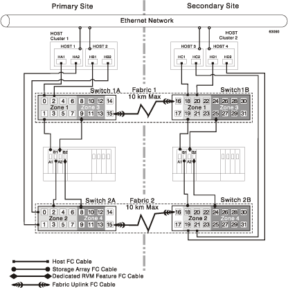
The Campus Configuration is a lower-cost configuration and consists of two storage arrays and two switches, connected using a Fibre Channel fabric as shown in Figure 3-13. The primary storage array and secondary storage array may have a maximum connection distance of up to 10 km (or 6.25 miles).
For detailed instructions on setting up this configuration, see “Hardware and Software Installation”.
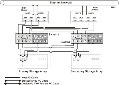
The Intra-Site Configur ation is the lowest-cost configuration which consists of two storage arrays and two switches, connected using a Fibre Channel fabric as shown in Figure 3-14. The primary storage array and secondary storage array may have a maximum connection distance of up to 500 m (or 0.32 miles) and would typically be located in the same building or in the same room.
For detailed instructions on setting up this configuration, see “Hardware and Software Installation”.
Complete the following checklists to ensure that all the required hardware and software components have been configured properly.
Complete the tasks in Table 3-1 before starting the storage management software.
Task Description |
| Validation Activity |
|---|---|---|
1. | Ensure that the minimum hardware requirements have been met.
For a complete list of the hardware requirements, see “Hardware Requirements” . | __ Completed. |
2. | Ensure your primary and secondary storage arrays have been properly configured.
See the SGI TP9500 RAID Installation and Upgrade Guide for storage array configuration information. | __ Completed. |
3. | Ensure that your switches and cables have been properly configured.
For more information on configuring switches for use with the Remote Volume Mirroring feature, see “Hardware and Software Installation” . | __ Completed. |
Complete the tasks in Table 3-2 before establishing mirror relationships in your storage arrays.
Task Description |
| Validation Activity |
|---|---|---|
1. | Ensure that data on the primary and secondary storage arrays participating in Remote Volume Mirroring have been backed up. | __ Completed. |
2. | Ensure that the correct version of firmware and storage management software has been installed.
For more information on upgrading firmware or installing the storage management software, see “Hardware and Software Installation” . | __ Completed. |
3. | Ensure that the Remote Volume Mirroring premium feature has been enabled on both the primary and secondary storage arrays.
For more information on enabling premium features, see “Hardware and Software Installation” or the Array Management window online help. | __ Completed. |
4. | Ensure that the Remote Volume Mirroring feature has been activated and that a mirror repository volume has been created for each controller on the primary storage array.
For more information on activating the Remote Volume Mirroring feature, see “Using the Remote Volume Mirroring Premium Feature” . | __ Completed. |
5. | Ensure that the required primary and secondary volumes have been created on the primary and secondary storage arrays.
For more information on establishing a mirror relationship, see “Using the Remote Volume Mirroring Premium Feature” . | __ Completed. |
This section presents information necessary to install hardware and software to run the Remote Volume Mirroring premium feature. The beginning of the section explores the steps that need to be completed before any hardware or software installation. Next, hardware installation procedures are presented, followed by software installation procedures. This section is to be followed sequentially, from start to end.
This section provides necessary pre-installation information, such as site preparation, hardware and software requirements, and concepts that should be reviewed and completed before beginning any hardware or software installation procedures.
The Remote Volume Mirroring feature utilizes Fibre Channel switches creating a fabric environment for data replication. These switches require only minimal additional site preparation requirements beyond basic storage array operation.
For basic site preparation considerations including the use of Fibre Channel cables and connections, see the SGI TP9400 and SGI TP9500 RAID Owner's Guide.
For additional site preparation considerations concerning the Fibre Channel switches, including power requirements and physical dimensions/requirements, see the documentation provided by the switch manufacturer.
Ensure that all of the required hardware and software are available before proceeding. For a list of requirements, see “Hardware and Software Installation”.
Because of possible restrictions at the host level, the supported Remote Volume Mirroring configurations contain Fibre Channel switches zoned so a single host adapter can access only one controller per storage array . Additionally, all configurations utilize a separate zone for the ports reserved for the Remote Volume Mirroring feature.
| Note: The uplink port that connects (cascades) switches within a fabric should not be zoned. |
Switch zoning configurations are typically set up using management software provided by the manufacturer of the Fibre Channel switch. This software should be included with the materials provided when the switch was purchased.
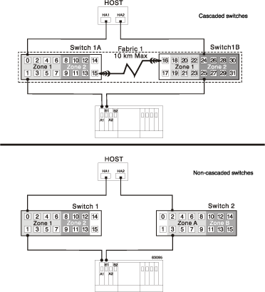
When two or more Fibre Channel switches are cascaded together, the switch management software will combine the ports for all switches that are linked. For example, if two 16-port Fibre Channel switches are cascaded with a physical connection using a Fibre Channel cable, the switch management software will show ports 0 through 31 participating in the fabric rather than 2 switches each with ports 0 through 15. Therefore, a zone that is created containing any of these ports can exist on multiple cascaded switches.
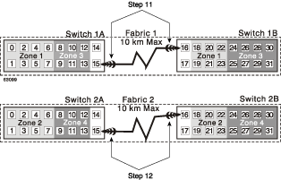
In Figure 3-15, the top set of switches are on the same network and cascaded, therefore Zone 1 is the same zone on Switch 1A as Zone 1 on Switch 1B. The bottom set of switches are on the same network, but are not cascaded. Even though both contain a Zone 1 (shown as Zone A in Switch 2), these zones are independent of each other.
For more information about Fibre Channel switch zoning or setting up a zone configuration, see the manufacturer's documentation provided with the switch.
Due to the varying Remote Volume Mirroring configurations, the switch zone settings are presented preceeding each configuration illustration in this chapter.
This section describes the procedures necessary to properly connect and configure one or more storage arrays for use with the Remote Volume Mirroring feature.
The configurations covered in this section are as follows.
Highest Availability Campus Configuration – This is the recommended configuration for the Remote Volume Mirroring feature. Four total switches (two at each site) provide for complete redundancy in the Fibre Channel switches and fabrics in addition to all storage array components and hosts. There is no single point of failure in this configuration. To begin installing hardware for this configuration, go to the next section, “Highest Availability Campus Configuration”.
Campus Configuration – This configuration is not fully redundant because the number of Fibre Channel switches is reduced from four to two and the number of fabrics from two to one. Consequently, this makes the switches and fabrics a single point of failure. A switch failure does not usually result in a loss of data, but does affect data synchronization until the error is corrected. Therefore, the Highest Availability Campus Configuration is the recommended configuration because data synchronization can continue for any single switch failure. This configuration essentially allows the minimum required components to successfully operate the Remote Volume Mirroring premium feature between two sites up to 10 km (6.25 miles). To begin installing hardware for this configuration, go to “Campus Configuration”.
Intra-Site Configuration – This configuration is similar to the Campus Configuration because there are only two switches. However, no multiple-switch fabrics exist in this configuration. Since all hosts and storage arrays are in proximity of both Fibre Channel switches, full redundancy can be obtained within the site since each controller path is connected to a different switch. Despite being a fully redundant configuration, the Highest Availability Campus Configuration is still recommended because of disaster recovery implications. The single site creates a single point of failure if a disaster affects the entire site. To begin installing hardware for this configuration, go to “Intra-Site Configuration”.
For a list of required materials to complete any hardware installation, see “Hardware and Software Installation”.
| Note: The Highest Availability Campus Configuration is the recommended configuration for the Remote Volume Mirroring feature. |
This configuration has two Fibre Channel switches at both the primary and secondary sites to provide for complete failover and redundancy for failures in Fibre Channel switches and cables, in addition to any host or storage array failure. Two Fibre Channel switches at each site also provide redundancy to the local site in addition to a fully redundant remote configuration. There is no single point of failure in the hardware components.
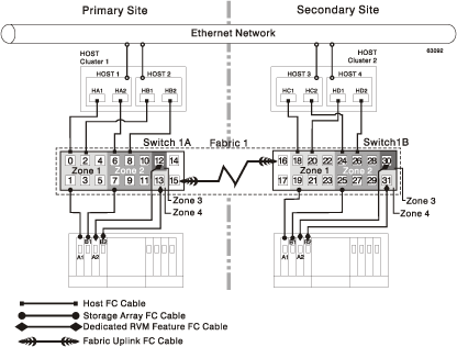
Figure 3-16 shows the Highest Availability Campus Configuration after installation is complete.
Switch Zoning for the Highest Availability Campus Configuration
This configuration allows for a separate zone for each reserved p ort for the Remote Volume Mirroring feature.
The switches do not need to be zoned exactly as presented in this configuration. However, the following are requirements when zoning switches for the Highest Availability Campus Configuration.
There will be a total of four zones in this configuration.
Zones 1 and 3 will exist on Fabric 1 (Switch 1A at the primary Site, and Switch 1B at the secondary site).
Zones 2 and 4 will exist on Fabric 2 (Switch 2A at the primary Site, and Switch 2B at the secondary site).
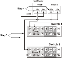
Configure the zones on the switch so that there is one port per zone for a storage array connection and one port per zone for each host.
The uplink port must not be zoned on any Fibre Channel switch.
Switches are zoned so that a single host adapter can access only one controller per storage array.
The switches in Figure 3-17 contain 16 ports each, which leaves many unused ports per switch. The remaining ports can be distributed among the other zones. However, it is recommended that most remaining ports be assigned to the zones containing the host connections (Zones 1 and 2 in Figure 3-17). This will allow easy set up for additional hosts to connect to the environment.
Figure 3-17 shows how the four switches are zoned for the Highest Availability Campus Configuration.
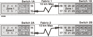
Given the requirements and the zoning shown in Figure 3-17, ensure that all four switches are properly zoned before proceeding. For more information on Zoning switches, see “Switch Zoning Overview”.
Cabling for the Highest Availability Campus Configuration
Table 3-3 is provided for a convenient reference of port connections.
Table 3-3. Highest Availability Campus Configuration Connections
Site | Switch | Zone | Port | Connect To/From |
|---|---|---|---|---|
Primary | 1A | 1 | 0 | Host 1, HBA 1 (HA1) |
Primary | 1A | 1 | 1 | Controller Port A1 |
Primary | 1A | 1 | 2 | Additional Host, HBA 1 (Optional) |
Primary | 1A | 1 | 3 | Additional Host, HBA 1 (Optional) |
Primary | 1A | 1 | 4 | Additional Host, HBA 1 (Optional) |
Primary | 1A | 1 | 5 | Additional Host, HBA 1 (Optional) |
Primary | 1A | 1 | 6 | Additional Host, HBA 1 (Optional) |
Primary | 1A | 1 | 7 | Additional Host, HBA 1 (Optional) |
Primary | 1A | 3 | 8 | Unused |
Primary | 1A | 3 | 9 | Controller Port A2 (Dedicated RVM Port) |
Primary | 1A | 3 | 10 | Unused |
Primary | 1A | 3 | 11 | Unused |
Primary | 1A | 3 | 12 | Unused |
Primary | 1A | 3 | 13 | Unused |
Primary | 1A | None | 14 | Spare (May be added to either Zone) |
Primary | 1A | None | 15 | Uplink with Switch 1B |
Primary | 2A | 2 | 0 | Host 2, HBA 2 (HB2) |
Primary | 2A | 2 | 1 | Host 1, HBA 2 (HB2) |
Primary | 2A | 2 | 2 | Controller Port B1 |
Primary | 2A | 2 | 3 | Additional Host, HBA 2 (Optional) |
Primary | 2A | 2 | 4 | Additional Host, HBA 2 (Optional) |
Primary | 2A | 2 | 5 | Additional Host, HBA 2 (Optional) |
Primary | 2A | 2 | 6 | Additional Host, HBA 2 (Optional) |
Primary | 2A | 2 | 7 | Additional Host, HBA 2 (Optional) |
Primary | 2A | 4 | 8 | Controller Port B2 (Dedicated RVM Port) |
Primary | 2A | 4 | 9 | Unused |
Primary | 2A | 4 | 10 | Unused |
Primary | 2A | 4 | 11 | Unused |
Primary | 2A | 4 | 12 | Unused |
Primary | 2A | 4 | 13 | Unused |
Primary | 2A | None | 14 | Spare (May be added to either Zone) |
Primary | 2A | None | 15 | Uplink with Switch 2B |
Secondary | 1B | None | 16 | Uplink with Switch 1A |
Secondary | 1B | None | 17 | Spare (May be added to either Zone) |
Secondary | 1B | 1 | 18 | Host 3, HBA 1 (HC1) |
Secondary | 1B | 1 | 19 | Controller Port A1 |
Secondary | 1B | 1 | 20 | Host 4, HBA 1 (HD1) |
Secondary | 1B | 1 | 21 | Additional Host, HBA 1 (Optional) |
Secondary | 1B | 1 | 22 | Additional Host, HBA 1 (Optional) |
Secondary | 1B | 1 | 23 | Additional Host, HBA 1 (Optional) |
Secondary | 1B | 3 | 24 | Unused |
Secondary | 1B | 3 | 25 | Controller Port A2 (Dedicated RVM Port) |
Secondary | 1B | 3 | 26 | Unused |
Secondary | 1B | 3 | 27 | Unused |
Secondary | 1B | 3 | 28 | Unused |
Secondary | 1B | 3 | 29 | Unused |
Secondary | 1B | 3 | 30 | Unused |
Secondary | 1B | 3 | 31 | Unused |
Secondary | 2B | None | 16 | Uplink with Switch 2A |
Secondary | 2B | None | 17 | Spare (May be added to either Zone) |
Secondary | 2B | 2 | 18 | Controller Port B1 |
Secondary | 2B | 2 | 19 | Host 4, HBA 2 (HD2) |
Secondary | 2B | 2 | 20 | Additional Host, HBA 2 (Optional) |
Secondary | 2B | 2 | 21 | Host 3, HBA 2 (HC2) |
Secondary | 2B | 2 | 22 | Additional Host, HBA 2 (Optional) |
Secondary | 2B | 2 | 23 | Additional Host, HBA 2 (Optional) |
Secondary | 2B | 4 | 24 | Controller Port B2 (Dedicated RVM Port) |
Secondary | 2B | 4 | 25 | Unused |
Secondary | 2B | 4 | 26 | Unused |
Secondary | 2B | 4 | 27 | Unused |
Secondary | 2B | 4 | 28 | Unused |
Secondary | 2B | 4 | 29 | Unused |
Secondary | 2B | 4 | 30 | Unused |
Secondary | 2B | 4 | 31 | Unused |
| Note: Begin the installation at the primary site. Repeat these steps for the secondary site when instructed to do so. |
After the four Fibre Channel Switches are properly zoned, complete the following procedure to set up the Highest Availability Campus Configuration for the Remote Volume Mirroring feature.
| Note: All connections are completed using Fibre Channel cables of appropriate length. |
Is Remote Volume Mirroring feature equipment being added to an existing storage array environment?
Yes – Stop I/O from all hosts before proceeding. Go to 2.
No – This is a new storage array installation. Go to 3.
Power down all storage arrays, hosts, Fibre Channel switches, and all other equipment in the storage array environment.
Ensure that cabling between all controller enclosures and drive enclosures is complete as presented in the SGI TP9400 and SGI TP9500 RAID Owner's Guide.
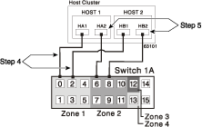
Note: Depending on which site is being configured, Switch 1 represents Switch 1A for the primary site, and Switch 1B for the secondary site. This applies to Switch 2 as well. Connect the primary host bus adapter (Hx1) for each local host to an available port in Zone 1 of Switch 1 (Figure 3-18).
Note: The cables can be connected to any port in the proper zone of the switch. Connect the secondary host bus adapter (Hx2) for each host at this site to an available port in Zone 2 of Switch 2 (Figure 3-18).
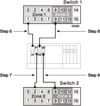
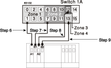
Connect controller port A1 of the storage array to an available port in Zone 1 of Switch 1 (Figure 3-19).
Connect controller port B1 of the storage array to an available port in Zone 2 of Switch 2 (Figure 3-19).
Connect controller port A2 of the storage array to an available port in Zone 3 of Switch 1 (Figure 3-19).
Connect controller port B2 of the storage array to an available port in Zone 4 of Switch 2 (Figure 3-19).
Note: Controller ports A2 and B2 are reserved for mirror relationship synchronization upon activation of the Remote Volume Mirroring feature. For more information, see “Connectivity and Input/Output”. The primary site cabling is now complete. Is the secondary site cabling complete?
No – Repeat steps 1 through 9 for the secondary site.
Yes – Go to step 11.
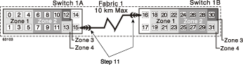
Complete the fabric environment for Switch 1 by connecting Switch 1A with Switch 1B. Connect each end of a long range Fibre Channel cable (up to 10 km in length) to an unzoned port in each switch (Figure 3-20).
Repeat step 11 for Switch 2A and 2B to complete the fabric environment for Switch 2 (Figure 3-20).
Cabling for the Highest Availability Campus Configuration is complete. Repeat 4 through 10 for any additional storage arrays that exist in the same cabinet that will use the Remote Volume Mirroring feature.
Power up all storage arrays, hosts, Fibre Channel switches, and any other hardware at both sites that was powered down in 2.
Hardware installation is complete. The next step will be to configure the storage management software to support mirror relationships. Go to “Software Installation”.
This configuration offers the same functionality as the Highest Availability Campus Configuration, but contains only one switch at each site, rather than two. The configuration is still redundant for host bus adapters, controllers, and Remote Volume Mirroring ports, but is a single point of failure for switches. If a switch at either site fails, the Remote Volume Mirroring Feature cannot function. For this reason, the Highest Availability Campus Configuration is highly recommended for total environment redundancy.
Figure 3-21 shows the Campus Configuration after installation is complete.
Switch Zoning for the Campus Configuration
This configuration allows for a separate zone for each reserved port for the Remote Volume Mirroring feature.
The switches do not need to be zoned exactly as presented in this configuration. However, the following are requirements when zoning switches for the Campus Configuration.
There will be a total of four zones in this configuration.
All zones will exist on Fabric 1 (Switch 1A at the primary site, and Switch 1B at the secondary site).
Zones 3 and 4 will be reserved for the dedicated Remote Volume Mirroring Feature connections.
Configure the zones on the switches so that there is one port per zone for a storage array connection and one port per zone for each host.
The uplink port must not be zoned on either Fibre Channel switch.
Switches are zoned so that a single host adapter can access only one controller per storage array.
The switches in Figure 3-22 contain 16 ports each, which leaves many unused ports per switch. The remaining ports can be distrib uted among the other zones. However, it is recommended that most remaining ports be assigned to the zones containing the host connections (Zone 1 in Figure 3-22). This will allow easy set up for additional hosts to connect to the environment.
Figure 3-22 shows how the two switches are zoned for the Campus Configuration.
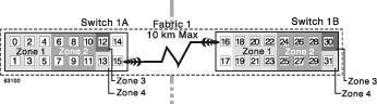
Given the requirements and the zoning example shown in Figure 3-22, ensure that both switches are properly zoned before proceeding. For more information on Zoning switches, see “Switch Zoning Overview”.
Cabling for the Campus Configuration
Table 3-4 is provided for a convenient reference of port connections.
Table 3-4. Campus Configuration Connections
Site | Switch | Zone | Port | Connect To/From |
|---|---|---|---|---|
Primary | 1A | 1 | 0 | Host 1, HBA 1 (HA1) |
Primary | 1A | 1 | 1 | Controller Port A1 |
Primary | 1A | 1 | 2 | Host 2, HBA 1 (HB1) |
Primary | 1A | 1 | 3 | Additional Host, HBA 1 (Optional) |
Primary | 1A | 1 | 4 | Additional Host, HBA 1 (Optional) |
Primary | 1A | 1 | 5 | Additional Host, HBA 1 (Optional) |
Primary | 1A | 2 | 6 | Host 1, HBA 2 (HA2) |
Primary | 1A | 2 | 7 | Controller Port B1 |
Primary | 1A | 2 | 8 | Host 2, HBA 2 (HB2) |
Primary | 1A | 2 | 9 | Additional Host, HBA 2 (Optional) |
Primary | 1A | 2 | 10 | Additional Host, HBA 2 (Optional) |
Primary | 1A | 2 | 11 | Additional Host, HBA 2 (Optional) |
Primary | 1A | 3 | 12 | Controller Port B2 (Dedicated RVM Port) |
Primary | 1A | 4 | 13 | Controller Port B2 (Dedicated RVM Port) |
Primary | 1A | None | 14 | Spare (May be added to any Zone) |
Primary | 1A | None | 15 | Uplink with Switch 1B |
Secondary | 1B | None | 16 | Uplink with Switch 1A |
Secondary | 1B | None | 17 | Spare (May be added to any Zone) |
Secondary | 1B | 1 | 18 | Host 3, HBA 1 (HC1) |
Secondary | 1B | 1 | 19 | Controller Port A1 |
Secondary | 1B | 1 | 20 | Host 4, HBA 1 (HD1) |
Secondary | 1B | 1 | 21 | Additional Host, HBA 1 (Optional) |
Secondary | 1B | 1 | 22 | Additional Host, HBA 1 (Optional) |
Secondary | 1B | 1 | 23 | Additional Host, HBA 1 (Optional) |
Secondary | 1B | 2 | 24 | Host 3, HBA 2 (HC2) |
Secondary | 1B | 2 | 25 | Controller Port B1 |
Secondary | 1B | 2 | 26 | Host 4, HBA 2 (HD2) |
Secondary | 1B | 2 | 27 | Additional Host, HBA 2 (Optional) |
Secondary | 1B | 2 | 28 | Additional Host, HBA 2 (Optional) |
Secondary | 1B | 2 | 29 | Additional Host, HBA 2 (Optional) |
Secondary | 1B | 3 | 30 | Controller Port A2 (Dedicated RVM Port) |
Secondary | 1B | 4 | 31 | Controller Port B2 (Dedicated RVM Port) |
| Note: Begin the installation at the primary site. Repeat these steps for the secondary site when instructed to do so. |
After both Fibre Channel Switches are properly zoned, complete the following procedure to set up the Campus Configuration for the Remote Volume Mirroring feature.
| Note: All connections are completed using Fibre Channel cables of appropriate length. |
Is Remote Volume Mirroring feature equipment being added to an existing storage array environment?
Yes – Stop I/O from all hosts before proceeding. Go to step 2.
No – This is a new storage array installation. Go to step 3.
Power down all storage arrays, hosts, Fibre Channel switches, and all other equipment in the storage array environment.
Ensure that basic cabling between all controller enclosures and drive enclosures is complete as presented in the SGI TP9400 and SGI TP9500 RAID Owner's Guide.
Note: Depending on which site is being configured, Switch 1 represents Switch 1A for the primary site, and Switch 1B for the secondary site. Connect the primary host bus adapter (Hx1) for each host at this site to an available port in Zone 1 of Switch 1 (Figure 3-23).
Note: The cables can be connected to any port in the proper zone of the switch. Connect the secondary host bus adapter (Hx2) for each host at this site to an available port in Zone 2 of Switch 1 (Figure 3-23).
Connect controller port A1 of the storage array to an available port in Zone 1 of Switch 1 (Figure 3-24).
Connect controller port B1 of the storage array to an available port in Zone 2 of Switch 1 (Figure 3-24).
Connect controller port A2 of the storage array to an available port in Zone 3 of Switch 1 (Figure 3-24).
Connect controller port B2 of the storage array to an available port in Zone 4 of Switch 1 (Figure 3-24).
Note: Controller ports A2 and B2 are reserved for mirror relationship synchronization upon activation of the Remote Volume Mirroring feature. For more information, see “Connectivity and Input/Output”. The primary site cabling is now complete. Is the secondary site cabling complete?
No – Repeat steps 1 through 9 for the secondary site.
Yes – Go to step 11.
Complete Fabric 1 by connecting Switch 1A with Switch 1B. Connect each end of a long range Fibre Channel cable (up to 10 km in length) to an unzoned port in each switch (Figure 3-25).
Cabling for the Campus Configuration is complete. Repeat steps 4 through 10 for any additional storage arrays that exist in the same cabinet that will use the Remote Volume Mirroring feature.
Power up all storage arrays, hosts, Fibre Channel switches, and any other hardware at both sites that was powered down in step 2.
Hardware installation is complete. The next step will be to configure the storage management software to support mirror relationships. Go to “Software Installation”.
This configuration is u sed in environments where a long distance fabric is not required because of the close proximity of the hosts and storage arrays. The configuration is still redundant for host bus adapters, controllers, Remote Volume Mirroring ports, and switches, but is a single point of failure for the site since all equipment can be destroyed by the same disaster. For this reason, the Highest Availability Campus Configuration is highly recommended for total environment redundancy.
| Note: A switch failure in this configuration does not affect data access, however, an unsynchronized mirror state may occur as a result. |
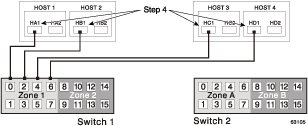
Figure 3-26 shows the Intra-Site Configuration after installation is complete.
Switch Zoning for the Intra-Site Configuration
This configuration is designed for switch redundancy. However, the switches are not cascaded, and are therefore independent of each other. The switches do not need to be zoned exactly as presented in this configuration. However, the following are requirements when zoning switches for the Intra-Site Configuration.
| Note: Switch 2 contains Zones A and B to show that there is no relationship between Switch 1 and Switch 2, contrary to the other configurations. |
There will be a total of four zones in this configuration.
Zones 1 and 2 will exist on Switch 1.
Zones A and B will exist on Switch 2.
Configure the zones on the switch so that there is one port per zone for a storage array connection and one port per zone for each host.
Switches are zoned so that a single host adapter can only access one controller per storage array.
The switches in Figure 3-27 contain 16 ports each, which leaves many unused ports per switch. The remaining ports can be distribut ed among the other zones. However, it is recommended that most remaining ports be assigned to the zones containing the host connections (Zone 1 and Zone A in Figure 3-27). This will allow easy set up for additional hosts to connect to the environment.
In this example, the switches use half of the ports for each zone for simplicity, although Zone 2 and Zone B require less ports.

Given the requirements and the zoning example shown in Figure 3-27, ensure both switches are properly zoned before proceeding. For more information on zoning switches, see “Switch Zoning Overview”.
Cabling for the Intra-Site Configuration
Table 3-5 is provided for a convenient reference of port connections.
Table 3-5. Intra-Site Configuration Connections
Site | Switch | Zone | Port | Connect To/From |
|---|---|---|---|---|
Primary | 1 | 1 | 0 | Host 1, HBA 1 (HA1) |
Primary | 1 | 1 | 1 | Controller Port A1 (Primary Storage Array) |
Primary | 1 | 1 | 2 | Host 2, HBA 1 (HB1) |
Primary | 1 | 1 | 3 | Controller Port A1 (Secondary Storage Array) |
Primary | 1 | 1 | 4 | Host 3, HBA 1 (HC1) |
Primary | 1 | 1 | 5 | Additional Host, HBA 1 (Optional) |
Primary | 1 | 1 | 6 | Host 4, HBA 1 (HD1) |
Primary | 1 | 1 | 7 | Additional Host, HBA 1 (Optional) |
Primary | 1 | 2 | 8 | Unused |
Primary | 1 | 2 | 9 | Controller Port A2 (Primary Storage Array - Dedicated RVM Port) |
Primary | 1 | 2 | 10 | Unused |
Primary | 1 | 2 | 11 | Controller Port A2 (Secondary Storage Array - Dedicated RVM Port) |
Primary | 1 | 2 | 12 | Unused |
Primary | 1 | 2 | 13 | Unused |
Primary | 1 | 2 | 14 | Unused |
Primary | 1 | 2 | 15 | Unused |
Secondary | 2 | A | 0 | Host 1, HBA 2 (HA2) |
Secondary | 2 | A | 1 | Controller Port B1 (Primary Storage Array) |
Secondary | 2 | A | 2 | Host 2, HBA 2 (HB2) |
Secondary | 2 | A | 3 | Controller Port B1 (Secondary Storage Array) |
Secondary | 2 | A | 4 | Host 3, HBA 2 (HC2) |
Secondary | 2 | A | 5 | Additional Host, HBA 2 (Optional) |
Secondary | 2 | A | 6 | Host 4, HBA 2 (HD2) |
Secondary | 2 | A | 7 | Additional Host, HBA 2 (Optional) |
Secondary | 2 | B | 8 | Unused |
Secondary | 2 | B | 9 | Controller Port B2 (Primary Storage Array - Dedicated RVM Port) |
Secondary | 2 | B | 10 | Unused |
Secondary | 2 | B | 11 | Controller Port B2 (Secondary Storage Array - Dedicated RVM Port) |
Secondary | 2 | B | 12 | Unused |
Secondary | 2 | B | 13 | Unused |
Secondary | 2 | B | 14 | Unused |
Secondary | 2 | B | 15 | Unused |
After both Fibre Channel Switches are properly zoned, complete the following procedure to set up the Intra-Site Configuration for the Remote Volume Mirroring feature.
| Note: All connections are completed using Fibre Channel cables of appropriate length. |
Is Remote Volume Mirroring feature equipment being added to an existing storage array environment?
Yes – Stop I/O from all hosts before proceeding. Go to step 2.
No – This is a new storage array installation. Go to step 3.
Power down all storage arrays, hosts, Fibre Channel switches, and all other equipment in the storage array environment.
Ensure that basic cabling between all controller enclosures and drive enclosures is complete on both storage arrays as presented in the SGI TP9400 and SGI TP9500 RAID Owner's Guide.
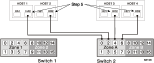
Connect the primary host bus adapter for each host (Hx1) to an available port in Zone 1 of Switch 1 (Figure 3-28).
Note: The cables can be connected to any port in the proper zone of the switch. Connect the secondary host bus adapter (Hx2) for each host to an available port in Zone A of Switch 2 (Figure 3-29).
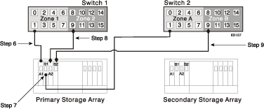
Connect controller port A1 of the primary storage array to an available port in Zone 1 of Switch 1 (Figure 3-30).
Connect controller port B1 of the primary storage array to an available port in Zone A of Switch 2 (Figure 3-30).
Connect controller port A2 of the primary storage array to an available port in Zone 2 of Switch 1 (Figure 3-30).
Connect controller port B2 of the primary storage array to an available port in Zone B of Switch 2 (Figure 3-30).
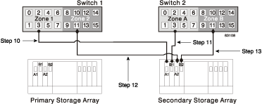
Note: Controller Ports A2 and B2 are reserved for mirror relationship synchronization upon activation of the Remote Volume Mirroring feature. For more information, see “Connectivity and Input/Output”. Connect controller port A1 of the secondary storage array to an available port in Zone 1 of Switch 1 (Figure 3-31).
Connect controller port B1 of the secondary storage array to an available port in Zone A of Switch 2 (Figure 3-31).
Connect controller port A2 of the secondary storage array to an available port in Zone 2 of Switch 1 (Figure 3-31).
Connect controller port B2 of the secondary storage array to an available port in Zone B of Switch 2 (Figure 3-31).
Cabling for the Intra-Site Configuration is complete. Repeat steps 4 through 13 for any additional storage arrays that exist in the same cabinet that will use the Remote Volume Mirroring feature.
Power up all storage arrays, hosts, Fibre Channel switches, and any other hardware that was powered down in step 2.
Hardware installation is complete. The next step will be to configure the storage management software to support mirror relationships. Go to “Software Installation”.
The Remote Volume Mirroring premium feature is automatically included as part of the Total Performance Storage System Manager version 8.3x installation. However, the feature is not enabled or activated by default after installation.
| Note: All storage arrays participating in mirror relationships must have firmware version 5.3x or later installed. For more information about upgrading firmware, see the TP9500 Release Notes. |
For more information about installing Total Performance Storage System Manager version 8.3x and later, see the SGI TPSSM Administration Guide.
For more information about enabling or activating the Remote Volume Mirroring premium feature, see “Enabling and Activating the Remote Volume Mirroring Feature”.
All hardware and software is n ow set up to support mirror relationships through the Remote Volume Mirroring feature. However, before creating mirror relationships, ensure that all required components are working properly.
Complete the following procedure for each storage array that will participate in any aspect of a mirror relationship to verify correct configuration.
Start the storage management software.
For more information about starting the storage management software, see the SGI TPSSM Administration Guide for operating system specific procedures.
Is this the first time the storage management software has been started?
Yes – Go to step 3.
No – Go to step 4.
Start the storage management software (for the first time).
Select OK when prompted for Automatic Discovery of devices.
Ensure that all storage arrays designated to participate in mirror relationships are displayed in the Device Tree view of the Enterprise Management window.
Start the storage management software (not for the first time).
From the Enterprise Management window, select Tools \> Automatic Discovery.
Select OK.
Verify that all storage arrays designated to participate in mirror relationships are displayed in the Device Tree view of the Enterprise Management window.
If the storage arrays do not appear, see “Troubleshooting”.
From the Enterprise Management window, select a storage array that will participate in mirror relationships.
Select Tools \> Manage Device to open the Array Management window for that storage array.
From the Array Management window, select Help \> About.
Verify that the version of the storage management software is 8.3x or later. If this requirement is not met, see the SGI TP9500 RAID Installation and Upgrade Guide for storage management software upgrade procedures.
Select OK.
From the Array Management window, select View \> Storage Array Profile.
Under the All tab, verify that the current firmware version is 5.3x or later. If this requirement is not met, see TP9500 Release Notes for firmware upgrade procedures.
Select Close.
Observe the Remote Mirroring premium feature icon in the premium feature status area. The icon represents a Disabled/Deactivated status of the Remote Volume Mirroring feature.
To begin working with Mirror Relationships, go to “Using the Remote Volume Mirroring Premium Feature”.
This section consists of procedures necessary to perform the major tasks associated with the Remote Volume Mirroring feature. The section is organized sequentially; after the feature has been enabled and activated, mirror relationships can be created and then maintained. The final subsection is provided for reference only and may be required when a mirror relationship is no longer needed.
The Remote Volume Mirroring premium feature must be enabled and activated before any mirror relationships can be created. First, determine the status of the Remote Volume Mirroring feature. After determining the status, the feature will need to be enabled and activated in order to perform all functions of the Remote Volume Mirroring feature.
There are four possible statuses of the Remote Volume Mirroring feature: Disabled/Deactivated, Disabled/Activated, Enabled/Deactivated, and Enabled/Activated.
| Note: The Remote Volume Mirroring feature must be in an Enabled/Activated state on the secondary storage array as well as the primary storage array to utilize all the functionality of the feature. |
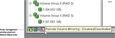
The current status can be determined by hovering the mouse pointer over the Remote Volume Mirroring feature icon in the premium feature status area of the Array Management window, as shown in Figure 3-32.
| Note: The Remote Volume Mirroring feature status for the primary storage array is managed independently from the secondary storage array. To determine the status for both storage arrays, select each storage array independently, then determine the status. |
The status of the Remote Volume Mirroring feature is one of the following.
Disabled/Deactivated – No functions of the Remote Volume Mirroring feature can be performed. Full Remote Volume Mirroring feature functionality is not available until the feature is enabled and activated. The icon for this state is displayed in the premium feature status area as a cylinder with a mirrored reflection. The icon has a red slash through it to show it is disabled, and is greyed out to show it is deactivated. An example of this state is illustrated in Figure 3-32. For more information about enabling the Remote Volume Mirroring feature, see “Enabling the Remote Volume Mirroring Feature”. To activate the feature, see “Activating the Remote Volume Mirroring Feature”.
Disabled/Activated – The Remote Volume Mirroring feature is disabled, preventing new mirror relationships from being created. However, any pre-existing mirror relationships can be maintained with all functions of the Remote Volume Mirroring feature. The icon displayed for this state is similar to the Disabled/Deactivated state, because the red slash remains to show the feature is disabled. However, the cylinder and its reflection now appear green to show the feature is active. For more information about enabling the Remote Volume Mirroring feature, see “Enabling the Remote Volume Mirroring Feature”.
Enabled/Deactivated – The Remote Volume Mirroring feature is enabled, but not activated. The icon displayed for this state is similar to the Disabled/Deactivated state, because the cylinder and its reflection remain grey. However, the red slash no longer appears, therefore, the feature is enabled. To activate the feature, see “Activating the Remote Volume Mirroring Feature”.
Enabled/Activated – The Remote Volume Mirroring feature is enabled and active. Mirror relationships can be created and maintained. The icon for this state is displayed in the premium feature status area as a green cylinder with a mirrored reflection. For more information about creating a mirror relationship, see “Creating Mirror Relationships”.
If the current status of the Remote Volume Mirroring feature is Disabled/Deactivated or Disabled/Activated, complete the following to enable the Remote Volume Mirroring feature.
From the Array Management window, select Storage Array \> Premium Features \> Enable.
The Select Feature Key File dialog is displayed.
Note: The Select Feature Key File dialog filters for files with the .key extension. Select the folder in which you placed the generated key file.
Select the appropriate key file, and then select OK.
The Enable Premium Feature dialog is displayed.
Select Yes.
The Remote Volume Mirroring premium feature is now enabled. The icon in the premium feature status area no longer displays a red slash. To further verify the status of the feature, select Storage Array \> Premium Features \> List.
Repeat step 1 through step 4 for the secondary storage array and any additional storage array that will participate in the Remote Volume Mirroring Feature.
Has the Remote Volume Mirroring feature been activated on both primary and secondary storage arrays?
No – Go to “Activating the Remote Volume Mirroring Feature”.
Yes – Go to “Creating Mirror Relationships”.
Activating the Remote Volume Mirroring feature prepares the storage array to create and configure mirror relationships. After the feature is activated, the secondary ports for each controller are reserved and de dicated to Remote Volume Mirroring feature usage. In addition, a mirror repository volume is automatically created for each controller in the storage array.
If the current status of the Remote Volume Mirroring feature is Enabled/Deactivated, complete the following to activate the premium feature.
From the Array Management window, select Storage Array \> Remote Volume Mirroring \> Activate.
The Activate Remote Volume Mirroring - Introduction dialog is displayed.
Note: Select Back at any time to change information in previous dialogs. Decide where the mirror repository volumes will reside. Select one of the following.
Use free capacity on existing volume group – If this option is selected, then a corresponding volume group must be selected as well.
Select a volume group.
Select Next.
Go to step 6.
Create a new volume group using unconfigured capacity – If this option is selected, more information must be collected about the new volume group. Go to step 3.
In the Create New Volume Group dialog, select the RAID level for the new volume group.
Under the drive selection choices, select one of the following.
Automatic – The drives are chosen automatically according to available capacity.
Manual – This option gives the user the option to specify which drives contain the mirror repository volume.
Note: RAID 0 is not an op tion, therefore, the number of drives selected must always be greater than one for all RAID levels. Note: RAID 3 and 5 require a minimum of 3 drives. Select the desired drives. Multiple drives can be selected by pressing Ctrl+click.
Select Apply.
Select Next.
Review the information in the Preview dialog, then select Finish if all information is satisfactory.
Is the storage array password protected?
Yes – Go to step 8.
No – Go to step 9.
Enter the password and select OK.
Review the information in the Completed dialog, then select OK to finish the Remote Volume Mirroring feature activation.
The Remote Volume Mirroring premium feature is now activated. The icon in the premium feature status area changes from grey to green.
Repeat step 1 through step 9 for the secondary storage array and any additional storage array that will participate in the Remote Volume Mirroring Feature.
Has the Remote Volume Mirroring feature been enabled on both primary and secondary storage arrays?
No – Go to “Enabling the Remote Volume Mirroring Feature”.
Yes – Go to “Creating Mirror Relationships”.
The Remote Volume Mirroring premium feature should be enabled and activated prior to creating mirror relationships. After the feature is enabled and activated, the secondary host po rts on the storage arrays are reserved for data synchronization between a primary and secondary volume of a mirror relationship, and mirror relationships can be created.
This subsection will present information for the following topics.
How to create volumes to be a primary or secondary volume in a mirror relationship, if not already created.
How to use the Create Remote Volume Mirror Wizard to create mirror relationships.
How to view mirror relationship configuration details.
Before any mirror relationships can be created, volumes must exist at both the primary and secondary sites. The volume residing in the primary storage array is the primary volume. Similarly, the volume residing in the secondary storage array is the secondary volume.
If a primary volume does not exist, one will need to be created on the primary storage array.
If a secondary volume does not exist, one will need to be created on the secondary storage array.
Consider the following when creating the secondary volume:
For more information about creating volumes, see the Array Management window online help.
When adequate volumes exist at both sites, mirror relationships can be created using the Remote Volume Mirror Wizard.
The Create Remote Volume Mirror Wizard allows a user to create a mirror relationship between a primary volume and a secondary volume.
Before beginning the wizard, ensure the following requirements are met.
The Remote Volume Mirroring premium feature is enabled on both storage arrays in which the primary and secondary volumes will reside.
The Remote Volume Mirroring feature is activated on both arrays.
The storage arrays are connected through a proper Fibre Channel fabric configuration.
The secondary volume is RAID level 0, 1, 3, or 5, and is of equal or greater size than the primary volume.
In the Logical/Physical View of the Array Management window, select the volume that will be the primary volume in the mirror relationship.
Select Volume \> Remote Volume Mirroring \> Create.
The Create Remote Volume Mirror dialog is displayed stating requirements similar to those mentioned at the beginning of this section.
Select Next.
Perform the procedure in the Select Remote Storage Array dialog.
Select the proper storage array.
Select Next.
Select the volume that will be the secondary volume in the mirror relationship.
Select Next.
Select the Synchronization Priority Level.
Note: For more information about the Synchronization Priority Level, see “Changing the Synchronization Priority Level”. Select Finish.
If the remote storage array is password protected, proceed to step 10, otherwise, go to step 11.
Enter the password and select OK.
Create another mirror relationship?
Yes – Complete the following steps:
Select the volume that will become the next primary volume.
Select Next.
Repeat steps 4 through 10 for each additional mirror relationship.
No – Go to step 12.
Review the information in the Completed dialog, then select OK to complete the Create Remote Volume Mirror Wizard.
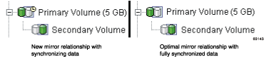
The primary and secondary volumes are now displayed with the mirror relationship icons, which will change slightly upon completion of the data synchronization. The amount of time for the data to be synchronized between the two volumes varies proportionally to the size of the volume being mirrored. After the synchronization is complete, the icons will change to the optimal state mirror relationship icons.
Note: To view all icons associated with the Remote Volume Mirroring feature and obtain a description of their purpose, refer to the Array Management window online help. Figure 3-33 shows how the icons appear during and after data synchronization.
The next step is maintaining the mirror relationship. Go to “Maintaining Mirror Relationships”.
Once a mirror relationship is active, certain attributes of the relationship can be modified at any time. This section describes how to view information about the mirror relationship, change the synchronization priority level, remove a mirror relationship, and delete volumes participating in a mirror relationship.
The mirror relationship that exists between the primary volume and the secondary volume can be examined by various methods, including: the Storage Array Profile, the Mirroring Properties dialog, and the View Associated Components dialog.
The Storage Array Profile
The Storage Array Profile is the most efficient way to view information about any or all components of the storage array. Details for all volumes, including the primary, secondary, and mirror repository volumes can all be easily viewed through the Storage Array Profile simultaneously. The Storage Array Profile also contains specific information for components associated with mirror relationships.
Complete the following procedure to display a Storage Array Profile.
From the Array Management window select View \> Storage Array Profile.
Select the Volumes tab.
To view information about the mirror relationships that exist on this storage array, select the Mirrors tab.
To view information about the mirror repository volume, select the Repositories tab.
Note: All information shown in the Storage Array Profile can be saved as a .txt file by selecting the Save as button. The Save Profile dialog that is displayed will have the option of saving the current window, multiple windows, or the entire Storage Array Profile.
The Mirroring Properties Dialog
The Mirroring Properties dialog displays all the physical characteristics of a single volume in the mirror relationship. The dialog displays the same information as the Storage Array Profile for the selected volume, but is specific to that volume. In addition, the synchronization progress is displayed if the selected volume is synchronizing data with another volume in a mirror relationship.
| Note: Use the following procedure to view the synchronization progress of a recently created mirror relationship. |
Complete the following procedure for each volume that needs to be examined in the mirror relationship.
Select the primary or secondary volume.
Select Volume \> Properties.
Select the Mirroring tab.
The View Associated Components Dialog
The View Associated Components dialog provides a more graphical representation of the volumes participating in the mirror relationship. In addition, more detail is given for all components, rather than only the selected volume.
Complete the following procedure to view all associated components in a mirror relationship, including primary, secondary, and mirror repository volumes.
Select the primary or secondary volume in a mirror relationship.
Select View \> Associated Components.
The View Associated Components dialog is displayed.
The Synchronization Priority Level of a mirror relationship defines the amount of system resources used to synchronize the data between the primary and secondary volumes of a mirror relationship. If the highest priority level is selected for a mirror relationship, the data synchronization uses a high amount of system resources to perform the full synchronization, but may decrease performance for host I/O, including other mirror relationships. Conversely, if the lowest synchronization level is selected, there is less impact on complete system performance, but the full synchronization may be slower.
To change the Synchronization Priority Level for a mirror relationship, complete the following procedure.
In the Logical/Physical View of the Array Management window, select a primary volume of a mirror relationship.
Select Volume \> Remote Volume Mirroring \> Change \> Synchronization Priority.
The Change Synchronization Priority dialog is displayed. The primary volume chosen in step 1 is selected by default in the Select Volumes selection area.
Select one or more volumes using the Select All button, Ctrl+click, or Shift+click.
Select the synchronization priority level by moving the slider bar. The five levels are Lowest, Low, Medium, High, and Highest. All selected volumes will change to the same synchronization priority level.
Select OK.
Select Yes when the Confirmation dialog is displayed.
Select OK when the Completed dialog is displayed.
Removing a mirror relationship between a primary and secondary volume does not affect any of the existing data on either volume. The link between the volumes is removed, but the primary volume still continues normal I/O operation. This action can be performed for backup routines, particularly from the secondary volume. A mirror relationship between the two volumes can be re-created unless one of the volumes is deleted.
To remove a mirror relationship between two volumes, complete the following procedure.
From the Array Management window, select a local primary volume or local secondary volume of a mirror relationship.
Select Volume \> Remote Volume Mirroring \> Remove Mirror Relationship.
The Remove Mirror Relationship dialog appears displaying all mirror relationships associated with this storage array.
Select one or more mirror relationships to remove using the Select All button, Ctrl+click, or Shift+click.
Carefully review the information presented in the Confirmation dialog.
Select Yes.
Deleting a volume participating in a mirror relationship removes the mirror relationship and completely deletes the volume from the storage array. The mirror relationship cannot be redefined until a new volume is created or an alternate volume is chosen to replace the deleted volume.
To delete a primary or secondary volume from a mirror relationship, complete the following procedure.
| Note: This action permanently removes data from the selected volume. |
From the Array Management window, select the primary or secondary volume that will be deleted.
Select Volume \> Delete.
The following information is displayed in the Delete Remote Volume Mirror dialog.

Caution: Carefully review the following information before proceeding with step 3. Deleting this volume will destroy all data on it, remove the mirror relationship that exists between it and its associated volume in the mirror pair, and increase the Free Capacity on the volume group. NOTE: The Data on the associated volume will not be deleted. Stop all I/O and unmount any file systems on this volume before proceeding IMPORTANT: If you see system error messages related to this deleted volume, you may need to reboot your host system to permanently remove any information about this volume. Are you sure you want to continue?
Type Yes in the text area to delete the volume.
Select OK.
If no mirror relationships exist and the Remote Volume Mirroring feature is no longer required, then deactivating the feature will reestablish normal use of dedicated ports on both storage arrays and delete both mirror repository volumes.
The Remote Volume Mirroring feature can also be disabled. When the feature is in the Disabled/Active state, previously existing mirrors can still be maintained and managed, however, new mirror relationships cannot be created. When in the Disabled/Deactivated state, no Remote Volume Mirroring feature activity can occur.
To change the Remote Volume Mirroring feature status from Enabled/Activated to Enabled/Deactivated or from Disabled/Activated to Disabled/Deactivated, complete the following procedure.
| Caution: This procedure will delete all mirror repository volumes on the current storage array. |
Verify that all mirror relationships have been removed. For more information, see “Removing Mirror Relationships”.
Select Storage Array \> Remote Volume Mirroring \> Deactivate.
Carefully review the information presented in the Confirmation dialog.
Select Yes.
To change the Remote Volume Mirroring feature status from Enabled/Deactivated to Disabled/Deactivated or from Enabled/Activated to Disabled/Activated, complete the following procedure.
From the Array Management window, select Storage Array \> Premium Features \> Disable.
Select Remote Volume Mirroring.
Select OK.
Carefully review the information presented in the Confirmation dialog.
Select Yes.
This section describes the actions to take to prepare for a disaster and the actions to take if a hardware component or complete site failure should occur.
As businesses require the ability to access critical data round-the-clock with little or no downtime, system administrators are required to ensure that critical data is safeguarded against potential disasters whether natural or man-made.
In preparing for a potential disaster, system administrators need to develop a disaster recovery plan that describes the procedures devised to prevent and prepare for disasters, and proposed actions for responding to and recovering from disasters if they occur.
This section provides information on the steps that should be undertaken in preparation for a possible disaster or catastrophic failure. Preparation steps discussed include backing up critical data prior to and during Remote Volume Mirroring, using host clustering software for failover protection, and preparing the secondary storage array that will participate in the Remote Volume Mirror.
The Remote Volume Mirroring checklist should be completed to ensure that your primary and secondary storage arrays are prepared correctly.
Backing up critical data regularly is vital insurance against disasters or catastrophic failure. Backups should be performed regardless of whether the Remote Volume Mirroring feature is in use.
A backup of all critical data on both the primary and secondary storage arrays participating in Remote Volume Mirroring should be performed prior to creating a Remote Volume Mirror. Periodic backups of the primary storage array should be carried out after Remote Volume Mirrors are in use.
Backups to tape or disk can be made while I/O continues using the Snapcopy Volume premium feature, which captures a point-in-time image of a volume. For more information on using snapcopy volumes, see “Snapcopy Volumes” or the Array Management window online help.
When preparing for a potential disaster, ensure the secondary storage array, to which the data is being mirrored, is structured in the same manner as the primary storage array.
Prior to creating a Remote Volume Mirror, you will need to prepare your secondary storage array to ensure that storage partitions are defined and ready to function if secondary storage array volumes are promoted to primary roles.
Defining Storage Partitioning
The Storage Partitioning premium feature allows you to define which hosts have access to which volumes on the storage array and at what logical unit number. When configuring your secondary storage array, replicate the storage partitions that were previously defined on the primary storage array. This will ensure that after a role reversal is carried out, hosts will be able to access their required data.
For more information on Storage Partitioning, see “Using Other Premium Features and Remote Volume Mirroring” or the Array Management window online help.
Host failover clustering is a process in which the operating system and application software work together to provide continuous availability in the event of an application failure, hardware failure, or operating-system error. Software products that support remote failover may refer to global or geographic cluster management.
The Remote Volume Mirroring feature can be used in conjunction with remote host failover to provide complete redundancy of host systems and storage arrays. If a disaster occurs at the primary storage array, hosts at the secondary storage array will take over processing and initiate a role change to the secondary storage array.
Remote failover is not a requirement for a disaster recovery plan. Depending on the requirements for how quickly operations must be functioning at Optimal status again, mirroring the storage arrays and depending on manual startup of the remote hosts may be acceptable.
The checklist in Table 3-6 should be completed in preparation for disaster recovery. Complete the steps listed to ensure access to mirrored data is possible in the event of a disaster or catastrophic failure.
Table 3-6. Disaster Preparation Checklist
Task Description |
| Validation Activity |
|---|---|---|
1. | Ensure that all critical data has been backed up on both the primary and secondary storage arrays. | __ Completed. |
2. | Ensure that Storage Partitioning is in place on the secondary storage array. This will reduce any lag time when promoting a secondary volume to the primary volume role.
For more information on setting up Storage Partitioning, see the Array Management window online help. | __ Completed. |
3. | If possible, ensure that the your host clustering software is configured to allow host failover between the primary storage array and secondary storage array participating in Remote Volume Mirroring.
For more information, see your host clustering software documentation. | __ Completed. |
The Campus Configuration is the only configuration where each switch is a single point of failure. In all other configurations, if a switch fails, at least one other switch is configured to be an alternate path for all I/O. The single switch at each site is not only responsible for the communication between the two sites for the Remote Volume Mirroring feature, but for all host to storage array I/O as well.
If a switch fails in the Campus Configuration, the system administrator should decide whether or not to do a complete site failover. This decision should be based on the immediate availability of a backup switch or the time it will take to receive a replacement.
If a replacement switch is not readily available, one of the following temporary scenarios will need to occur until the switch can be replaced.
Direct connection between hosts and storage arrays – This will bypass the switch and allow normal I/O to continue. All mirror relationships will be suspended until a normal configuration is resumed. Since the storage arrays have a finite number of host connections, all hosts may not be able to access the storage array. For information on how to directly connect hosts and storage arrays, see the SGI TP9400 and SGI TP9500 RAID Owner's Guide.
Entire Site Failover – The switch at the primary site has failed, however, the switch at the secondary site is still functional, which allows all hosts to access the switch and storage arrays. Mirror relationships will be suspended until the primary storage array is recovered. If a complete site failover is needed to continue normal operations, see “Entire Site Failover Procedure”.
This section provides procedures for recovering storage systems where one of the following situations has occurred:
The primary storage array is damaged or destroyed.
Entire primary site is damaged or destroyed.
Both situations require a complete site failover from the primary site to the secondary site so that business operations can continue. For a secondary site failure, no site failover is necessary. If the primary volume is not damaged, then a full synchronization will occur when the site is recovered. If the primary storage array is damaged, follow the procedure in “Rebuilding a Damaged Site”.
| Note: The procedures in this section should be completed in the order presented to ensure that the affected site or storage array is recovered successfully. |
Entire site failover is necessary when an event occurs that inhibits normal operation to the primary site for an extended period of time.
Manually reverse the role of the secondary volume of the mirror relationship to the primary role. For more information, see “Reversing the Roles of Primary and Secondary Volumes”.
Have all hosts at the secondary site been properly configured for host failover?
Yes – Go to step 4.
No – Go to step 3.
Reinstall host cluster software and reconfigure settings as needed. For more information about installing and configuring host cluster software, refer to the documentation provided with the software.
Has Storage Partitioning been pre-configured so that proper hosts can access appropriate volumes?
Yes – Go to step 6.
No – Go to step 5.
Configure the storage partitioning so that host to volume access is identical to the primary site configuration. For more information about setting up storage partitioning, see “Using Other Premium Features and Remote Volume Mirroring”.
Resume normal operation with the secondary site acting as a new, fully-functioning primary site.
The entire site failover is complete. The primary site must now be reconfigured and the Remote Volume Mirroring environment must be re-created. The next step will depend on the resulting status of the storage array from the disaster.
Is the storage array and all the contained data recovered and fully operational?
Yes – Go to “Re-creating a Mirror Relationship”.
No – Go to “Rebuilding a Damaged Site”.
If a disaster occurs to the primary or secondary site that renders the storage array or all data on the storage array irreparable, then the site needs to be rebuilt with new equipment.
Complete the following procedure to rebuild a damaged site:
Obtain new storage arrays and any hosts and equipment needed to properly use the Remote Volume Mirroring feature. It is recommended that the new equipment have equal or greater hardware and software specifications than the damaged equipment.
Depending on the configuration, complete the switch zoning and hardware installation procedure as presented in “Hardware and Software Installation” for this site only.
Create a volume to replace the mirrored volume damaged on the original storage array. The new volume should be identical to the specifications of the previously damaged volume.
Ensure storage partitioning is properly defined so that it may take over normal operation from the secondary site. For more information on setting up storage partitioning, see “Using Other Premium Features and Remote Volume Mirroring”.
Ensure the host cluster software is properly configured so that the hosts can take over I/O from the secondary site hosts. For more information about installing and configuring host cluster software, refer to the documentation provided with the software.
The damaged site is now ready to support mirror relationships. Go to “Re-creating a Mirror Relationship”.
After the damaged site is back online and properly configured, mirror relationships can be resumed by completing the following procedure.
From the undamaged site, remove all mirror relationships that existed prior to the disaster.
From the undamaged site, create a mirror relationship using the volume on the recovered primary site as the secondary volume. For more information, see “Maintaining Mirror Relationships”.
Ensure storage partitioning is properly defined on the recovered primary site so that it may take over normal operation from the secondary site. For more information on setting up storage partitioning, see “Using Other Premium Features and Remote Volume Mirroring”.
Ensure the host cluster software is properly configured so that the hosts at the recovered primary site can take over I/O from the secondary site hosts. For more information about installing and configuring host cluster software, see the documentation provided with the software.
Perform a role reversal so that the recovered primary site now possesses the active primary volume, and the secondary volume now exists on the secondary site. For more information, see “Reversing the Roles of Primary and Secondary Volumes”.
The Remote Volume Mirroring configuration is now ready.
A role reversal is the act of promoting the secondary volume to be the primary volume within the mirrored volume pair, and demoting the primary volume to be the secondary volume.
A role reversal may be performed using one of the following methods:
Changing a secondary mirrored volume to a primary volume – This option promotes the selected secondary volume to become the primary volume of the mirrored pair and would be used when a catastrophic failure has occurred. For step-by-step instructions, see “Changing a Secondary Volume to a Primary Volume”.
Changing a primary mirrored volume to a secondary volume – This option demotes the selected primary volume to become the secondary volume of the mirrored pair and would be used during normal operating conditions. For step-by-step instructions, see “Changing a Primary Volume to a Secondary Volume”.
Role reversals may also be performed using the set command in the Script Editor or the command line interface. For more information, see the Enterprise Management window online help.
A secondary volume is typically promoted to a primary volume role when a catastrophic failure has occurred to the storage array that contains the primary volume, and the secondary volume needs to be promoted so that hosts can access data and business operations can continue.
This option is not available unless the Remote Volume Mirroring premium feature has been activated.
| Note: When the secondary volume becomes a primary volume, any hosts that are mapped to the volume through a volume-to-LUN mapping will now be able to read or write to the volume. |
If a communication problem between the secondary and primary sites prevents the demotion of the remote primary volume, an error message is displayed. However, you are given the opportunity to proceed with the promotion of the secondary volume, even though this will lead to a dual-primary condition.
To promote a secondary volume to a primary role:
Select the secondary volume in the Logical view, then select Volume \> Remote Mirroring \> Change \> Role to Primary.
The Change to Primary dialog is displayed.
Select Yes. The secondary volume is promoted to be the primary volume role in the Remote Volume Mirror.
After the controller owner of the primary volume can be contacted, the primary volume is automatically demoted back to be the secondary role in the mirror relationship.
Changing a primary volume to a secondary role is used for role reversals during normal operating conditions. You can also use this option during a Recovery Guru procedure when a dual-primary condition occurs.
This option is not available unless the Remote Volume Mirroring premium feature has been activated.
| Note: Any hosts that are accessing the primary volume through a volume-to-LUN mapping will no longer be able to read or write to the volume. When the primary volume becomes a secondary volume, only remote writes initiated by the primary controller will be written to the volume. |
If a communication problem between the primary and secondary sites prevents the promotion of the secondary volume, an error message is displayed. However, you are given the opportunity to proceed with the demotion of the primary volume, even though this will lead to a dual-secondary condition.
If the selected primary volume has associated snapcopy volumes, demoting this volume to a secondary role will cause the associated snapcopy volumes to fail.
To demote a primary volume to a secondary role:
Select the primary volume in the Logical view, then select Volume \> Remote Mirroring \> Change \> Role to Secondary.
The Change to Secondary dialog is displayed.
Select Yes. The primary volume is demoted to be the secondary volume in the Remote Volume Mirror.
Once the controller owner of the secondary volume can be contacted, the secondary volume is automatically promoted back to the primary volume in the mirror relationship.
This chapter provides information about troubleshooting some of the more commonly encountered problems when using the Remote Volume Mirroring feature.
Troubleshooting topics include the following:
Locate the section that directly relates to your problem or consult the section describing general troubleshooting techniques. If your problem is not discussed in any of the sections in this chapter, contact technical support.
This subsection describes some of the typical problems that may be encountered when using the Remote Volume Mirroring premium feature. The information is presented in order from the time the feature is enabled and activated, to problems that may be encountered completing typical tasks when using the Remote Volume Mirroring feature.
Information about the probable cause and recommended resolution for each problem is provided. If your problem is not addressed in this section, see the remaining subsections in this section before contacting technical support.
The Remote Volume Mirroring menu options in the Array Management window are greyed out and unavailable.
Cause:
The Remote Volume Mirroring premium feature is not enabled or activated.
Resolution:
Enable the Remote Volume Mirroring premium feature. A feature key file is required to enable premium features. If one has not been supplied, contact your storage supplier.
Activate the Remote Volume Mirroring feature.
For step-by-step instructions on enabling and activating the Remote Volume Mirroring feature, see “Enabling and Activating the Remote Volume Mirroring Feature” or the Array Management window online help.
The Remote Volume Mirroring icon in the premium feature status area is greyed out with a red line.
Cause:
The Remote Volume Mirroring premium feature is not enabled or activated.
Resolution:
Enable the Remote Volume Mirroring premium feature. A feature key file is required to enable premium features. If one has not been supplied, contact your storage supplier.
Activate the Remote Volume Mirroring feature.
For step-by-step instructions on enabling and activating the Remote Volume Mirroring feature, see “Enabling and Activating the Remote Volume Mirroring Feature” or the Array Management window online help.
When creating a Remote Volume Mirror, an error message listing the code INVALID_MIRROR_CANDIDATE_VOL is received.
Cause:
The secondary volume candidate was participating in a mirror relationship with a different volume on this storage array. The mirror relationship was successfully removed from the other storage array. However, a communication error prevented the successful removal of the mirror relationship on this storage array.
A volume on this storage array still has a mirror relationship with the secondary volume candidate.
Resolution:
Select the View > Storage Array Profile option, then select the Volumes tab and the Mirrors tab.
Locate the volume that is still participating in the mirror relationship with the secondary volume candidate and remove the mirror relationship. For step-by-step instructions, see “Removing Mirror Relationships” or the Array Management window online help.
Re-create the intended Remote Volume Mirror using the original candidate volumes. For step-by-step instructions, see “Creating a Mirror Relationship Using the Create Remote Volume Mirror Wizard” or the Array Management window online help.
The primary volume is showing a Synchronization-in-Progress status.
Cause:
A full synchronization, between the primary and secondary volumes participating in a mirror relationship, is in progress. All data on the primary volume is being copied in its entirety to its associated secondary volume.
Resolution:
Wait for the full synchronization to complete. After it has finished copying data from the primary volume to the secondary volume, the mirrored volume pair transitions to a Synchronized status.
For more information on monitoring the status of a Remote Volume Mirror, see the Array Management window online help.
Both the primary and secondary volumes are displayed as being the primary volume.
Cause:
A disaster or catastrophic failure has occurred on the storage array containing the primary volume, and the secondary volume has been promoted to the primary volume role.
The primary storage array is now operational, but unreachable because of a link failure. A forced promotion of the secondary volume has resulted in both the primary and secondary volumes viewing themselves in the primary volume role.
Resolution:
From the Array Management window of the primary site, select the primary volume.
Select Volume > Remote Volume Mirroring > Remove Mirror Relationship.
Note: The mirror relationship for the secondary volume will not be removed if there is a connection problem between the storage arrays. If the mirror relationship still exists at the secondary site, repeat steps 1 and 2 for the secondary volume from the secondary site Array Management window. Re-create the mirror relationship by completing “Creating a Mirror Relationship Using the Create Remote Volume Mirror Wizard”.
Both the primary and secondary volumes are displayed as being the secondary volume.
Cause:
In response to a dual primary volume condition, a role reversal was carried out and the primary volume was demoted to the secondary volume role.
The secondary storage array is operational, but unreachable because of a link failure. The forced demotion of the primary volume has resulted in both the primary and secondary volumes viewing themselves in the secondary volume role.
Resolution:
From the Array Management window of the primary site, select the local secondary volume.
Select Volume > Remote Volume Mirroring > Remove Mirror Relationship.
Note: The mirror relationship for the secondary site will not be removed if there is a connection problem between the storage arrays. If the mirror relationship still exists at the secondary site, repeat steps 1 and two for the secondary volume from the secondary site Array Management window. Re-create the mirror relationship by completing “Creating a Mirror Relationship Using the Create Remote Volume Mirror Wizard”.
The primary volume/secondary volume is displayed as being a Missing Volume.
Cause:
A physical hard drive on which a Remote Volume Mirror depends (primary volume, secondary volume) has been removed, and the volume is now displayed under the Missing Volumes node in the Logical view of the Array Management window.
Resolution:
If missing volumes are detected because drives have been accidentally removed, or are detected as missing because of a loss of power to the drive enclosures, recovery of these volumes is possible by:
Re-inserting the drives back into the drive enclosure.
Ensuring that the drive enclosure's power supplies are properly connected to an operating power source and have an Optimal status.
For more information, see Recovery Guru or contact technical support.
If the missing volume is no longer required, it may be deleted.
Note: Deleting a missing volume is a permanent action. Any associated volumes or volume-to-LUN mappings will also be deleted. For more information, see the Recovery Guru or the Array Management window online help.
The mirror relationship was removed successfully from the primary side, but not from the secondary side.
Cause:
When removing a mirror relationship, a link failure occurred between the primary and secondary storage arrays, and an error message was displayed.
The Array Management window for the primary storage array indicates that the mirror relationship has been removed successfully, however, the Array Management window for the secondary storage array indicates that the mirror relationship still exists.
Resolution:
Open the Array Management window for the secondary storage array and remove the mirror relationship.
For step-by-step instructions, see “Removing Mirror Relationships” or the Array Management window online help.
The mirror relationship was removed successfully from the secondary side, but not from the primary side.
Cause:
When removing a mirror relat ionship, a link failure occurred between the primary and secondary storage arrays.
The Array Management window for the secondary storage array indicates that the mirror relationship has been removed successfully, however, the Array Management window for the primary storage array indicates that the mirror relationship still exists, with the primary volume showing an Unresponsive status.
Resolution:
Open the Array Management window for the primary storage array and remove the mirror relationship.
For step-by-step instructions, see “Removing Mirror Relationships” or the Array Management window online help.
The primary volume is showing an Unsynchronized status.
Cause:
The Remote Volume Mirror is in an Unsynchronized status because the data mirrored between the primary volume and secondary volume is no longer identical. Typical causes for this status include link errors, a failed primary volume or secondary volume, or a dual primary or dual secondary error condition.
While the Remote Volume Mirror is in an Unsynchronized status, no mirroring activity will take place.
Resolution:
Once the controller owner of the primary volume can communicate with the controller owner of the secondary volume and the volume is online and optimal, a full synchronization will automatically take place. When a full synchronization begins, the Remote Volume Mirror transitions to a Synchronization-in-Progress status.
For information on monitoring the status of a Remote Volume Mirror, see the Array Management window online help.
Error message indicates that the Remote Volume Mirroring premium feature is out of compliance.
Cause:
The Remote Volume Mirroring premium feature is out of compliance. This normally occurs if a volume group with volumes participating in Remote Volume Mirroring, has been moved into the primary storage array and one of the following conditions now exists:
The Remote Volume Mirroring premium feature is not enabled on the selected storage array.
The Remote Volume Mirroring feature is enabled, but the current number of Remote Volume Mirrors created on the primary storage array exceeds the number of mirror relationships allowed for this storage array.
Resolution:
If the Remote Volume Mirroring feature is not enabled for the primary storage array:
Obtain a feature key for this feature from your storage supplier.
Enable the Remote Volume Mirroring premium feature. For step-by-step instructions, see “Creating a Mirror Relationship Using the Create Remote Volume Mirror Wizard” or the Array Management window online help.
If the Remote Volume Mirroring feature is enabled, but the current number of mirror relationships on the storage array exceeds the number of mirror relationships allowed for the storage array, reduce the number of mirror relationships to equal or less than the number of mirror relationships allowed. There can be up to 8 defined mirrors on an SGI TP9400 storage array (with 4774 RAID controllers) and up to 32 defined mirrors on an SGI TP9400 storage array (with 4884 RAID controllers) or an SGI TP9500 storage array.
For step-by step instructions, see “Removing Mirror Relationships” or the Array Management window online help.
The remote volume candidate is unresponsive and cannot be updated.
Cause:
The primary storage array is unable to notify the secondary storage array that its world wide name (WWN) has changed.
This may be the result of a controller in the primary storage array being swapped or removed. Storage array recovery procedures that result in configurations being reset could also cause a change to the WWN.
The first write to the primary volume will cause the mirrored volume pair to transition into an Unsynchronized status.
Resolution:
Remove all the existing mirror relationships from the primary storage array. For step-by-step instructions, see “Removing Mirror Relationships” or the Array Management window online help.
Re-establish the required mirror relationships. For step-by step instructions, see “Creating a Mirror Relationship Using the Create Remote Volume Mirror Wizard” or the Array Management window online help.
This subsection describes Fibre Channel fabric configuration problems that may be encountered after you have configured your storage arrays and have activated and enabled the Remote Volume Mirroring feature.
Information about the probable cause and recommended resolution for each problem is provided. If your problem is not addressed in this section, see the remaining subsections in this section before contacting technical support.
The primary volume is unable to contact the Fibre Channel fabric.
Cause:
Typically, this error occurs because of a failed Fibre Channel fabric or because of cabling between the primary and secondary storage arrays participating in a Remote Volume Mirror.
Resolution:
If the Fibre Channel fabric has failed:
Repair or replace the failed fabric.
If the Fibre Channel fabric is operational:
Check the configurations cabling. The cable should not go through a hub or be connected directly between storage arrays. Ensure that the cable is attached through a switch.
For step-by-step instructions on configuring storage arrays for Remote Volume Mirroring, see “Hardware and Software Installation”.
The primary volume is unable to communicate with the secondary storage array. The primary storage array can still communicate with the fabric.
Cause:
Typically, this error occurs when the secondary storage array has lost power or when network problems exist between the secondary storage array and the fabric.
Resolution:
Secondary storage array has no power:
If the secondary storage array has no power and is not operational, restore power to the storage array. For information on powering on storage arrays, see your hardware documentation.
Secondary storage array has power and is operational:
Check the network status. Ensure the secondary storage array is visible on the network. Ensure the cables are correctly connected. For step-by-step instructions on configuring storage arrays for Remote Volume Mirroring, see “Hardware and Software Installation”.
This subsection describes the impact of physical or logical storage array component failures on Remote Volume Mirroring functionality.
Information about the probable cause and recommended resolution for each problem is provided. If your problem is not addressed in this section, see the remaining subsections in this section before contacting technical support.
Following a role reversal, a snapcopy volume created for a primary volume indicates that it has failed.
Cause:
The base volume for the snapcopy volume is a primary volume involved in a mirror relationship. A role reversal was performed, demoting the primary volume to secondary volume status, resulting in a snapcopy volume on the secondary volume.
The base volume for a snapcopy volume cannot be a candidate for the secondary volume role in a Remote Volume Mirror, and the snapcopy volume is therefore failed.
Resolution:
Perform a role reversal to promote the secondary volume to the primary volume role. After the role reversal is complete, the snapcopy volume will return to Optimal status.
For step-by-step instructions, see “Changing a Secondary Volume to a Primary Volume” or the Array Management window online help.
The primary storage array controller indicates that it has failed.
Cause:
Failure of the owning controller on the primary storage array will typically cause the associated multi-path driver on the attached host system to transfer ownership of the alternate controller on the primary storage array.
When this occurs, the alternate controller on the primary storage array will begin forwarding newly-written data to its peer on the secondary storage array. The secondary controller will take ownership of the volume from its (secondary) peer controller. This is a reactive event, which occurs because of the arrival of a write request from the primary storage array to the non-owning controller on the secondary storage array.
Resolution:
Allow the ownership transfer to complete. Operations will continue in a normal fashion, with the alternate (typically the non-preferred) controller on the primary storage array interacting with the alternate controller on the secondary storage array.
Failure of the non-owning controller on the primary storage array will have no direct impact on the status of any Remote Volume Mirrors.
The secondary storage array controller indicates that it has failed.
Cause:
One of the following scenarios has occurred:
Controller A on the secondary storage array has failed, while Controller A is the owner of the primary volume.
Controller B on the secondary storage array has failed while Controller B is the owner of the primary volume.
In both scenarios, the mirrored volume pair transitions to the Unsynchronized status.
Resolution:
Restore the failed controller. For detailed recovery procedures, see the Recovery Guru.
Upon restoration of the failed controller, the primary storage array will automatically transition to a Synchronizing status to restore coherency between the volumes.
This subsection describes some common switch-related problems that may be encountered when using the Remote Volume Mirroring feature. The troubleshooting information provided relates to switches supported for use with this version of the storage management software. For a list of supported switches, see “Feature Concepts and Requirements”.
Information about the probable cause and recommended resolution for each problem is provided. If your problem is not addressed in this section, see the remaining subsections in this section before contacting technical support.
Host is unable to detect primary and secondary storage arrays participating in Remote Volume Mirroring.
Cause:
When two or more switches are cascaded together and have the same Domain ID, hosts will be unable to locate the target device. Each switch must have a unique Domain ID when attempting to cascade two switches together.
Resolution:
Change the Domain ID of one or more of your switches, ensuring that each one is unique. The Domain ID should be a unique number between 1 and 239, which is used to identify the switch to a Fibre Channel fabric.
For more information on setting a Domain ID, see your switch user documentation.
Critical Major Event Log (MEL) events are generated when an error occurs that can affect data availability or results in a degraded mode of operation. The storage management software responds by alerting the appropriate administrators using e-mail, SNMP trap, or other configured mechanisms.
Because administrative action is required to correct the problem, the storage array will generally enter a Needs Attention status. This causes the appropriate indications to be presented through the storage management software and an associated Recovery Guru procedure to be displayed when requested by the end user.
The following provides a description of critical MEL events, with a brief explanation of what caused the event to trigger, and the recommended resolution. If your problem is not addressed in this section, see the remaining sections in this chapter before contacting technical support.
Mirrored pair becomes unsynchronized.
Cause:
This event is logged when a Remote Volume Mirror transitions to an Unsynchronized status, from either a Synchronization-in-Progress or Optimal status.
Resolution:
See the associated Recovery Guru message for specific recovery procedures.
Dual-role conflict detected.
Cause:
This event is logged when a dual-role conflict is detected, and is typically the result of a role reversal. Since both sides of the mirrored volume pair are in the same primary or secondary volume role, both the primary and secondary storage arrays will report this MEL event.
Resolution:
See the associated Recovery Guru message for specific recovery procedures.
Communication error with the secondary volume on the secondary, remote storage array.
Cause:
This event is logged when an interruption in the link that cannot be recovered by the firmware Fibre Channel driver is detected. Error codes and recovery procedures will assist the user in finding the exact cause of the communication problem between storage arrays participating in a mirror relationship.
Resolution:
See the associated Recovery Guru message for specific recovery procedures.
World wide name (WWN) change notification failed.
Cause:
This event is logged when a storage array detects during start-up processing that its world wide name (WWN) has changed. The WWN can only change if both controllers of the array are exchanged while the array is powered off.
When the firmware detects this name change, it attempts to notify any remote storage array that had previously been participating in a mirroring relationship with any volume on the array.
Resolution:
See the associated Recovery Guru message for specific recovery procedures.
The Remote Volume Mirroring feature is designed so that it is not necessary for the primary storage array and the secondary storage to be running exactly the same controller firmware level. All inter-controller operations (including those needed for propagation of newly-written data from the primary volume to the secondary volume) have been implemented so as to support mixed firmware levels to the greatest extent possible. This allows firmware upgrades to be performed on both the primary and secondary storage arrays without any loss of data.
This subsection describes the procedure that should be followed for upgrading controller firmware (version 5.30 and later), to ensure that the Remote Volume Mirroring features works as intended. The preferred sequence for performing firmware upgrades on storage arrays participating in mirror relationships is detailed below.
| Note: Depending on your storage array platform, you may not be able to select controller firmware version 5.40 and later. |
| Note: By following this sequence, it is possible to avoid transitions of the mirrored volume pair to an Unsynchronized status, avoiding the need for a full resynchronization afterwards. |
Stop I/O to applications that operate on all affected primary volumes temporarily inactive.
Download firmware to the secondary storage array.
Resume application access to primary volumes. There will be a period of time after this step where the primary storage array is operating with a different firmware level than the secondary storage array, but the inter-controller protocols for data replication will support such interactions.
Download firmware to the primary storage array.
Resume all I/O operations that were stopped in step 1.
It should be noted that some configuration operations, such as establishment of new mirrors and modification of mirror parameters, may not be allowed between storage arrays that have different firmware levels, and will result in error messages being received. However, the key data availability operations, including promotion from the secondary volume to the primary volume, will be allowed in such circumstances.