This chapter provides a description of the SGI 1450 server baseboard.
The topics covered in this chapter include:
Table 2-1 provides a summary of the baseboard features.
Feature | Description |
|---|---|
Processor | Up to four Intel Pentium III Xeon processors, packaged in single edge contact (S.E.C.) cartridges and installed in 330-pin SC330.1 compliant edge connectors, operating at 1.8 V to 3.5 V. The baseboard's voltage regulator is automatically programmed by the processor's VID pins to provide the required voltage. The baseboard includes connectors for three 8.3-compliant plug-in voltage-regulator modules (VRM). |
Memory, dynamic random access (DRAM) | Single plug-in module containing a 64- or 72-bit four-way-interleaved pathway to main memory supporting SDRAM. 256 MB to 16 GB of error correcting code (ECC) memory. A minimum of four DIMMs must be installed. |
Video memory (DRAM) | Installed: 2 MB of video memory. |
PCI Segment A bus | Two 184-pin, 3.3 V keyed, 64-bit PCI full-length expansion connectors (66/33 MHz). One DesotoE2 Hot-Plug PCI controller. |
PCI Segment B bus | Four 184-pin, 5 V keyed, 64-bit PCI full-length expansion connectors (33 MHz). One Adaptec AIC-7899 dual channel SCSI-3 Ultra 160 SCSI controller. One DesotoE2 Hot-Plug PCI controller. |
PCI Segment C bus | Two 120-pin, 32-bit PCI half-length expansion connectors (33 MHz). OSB4 I/O APIC. PCI network interface controller. ATI Rage IIc video controller. PCI narrow/wide Adaptec AIC-7880 Ultra SCSI controller. |
PCI Bus Master IDE Interface | The baseboard supports Ultra DMA33 Synchronous Direct Memory Access (DMA) mode transfers. |
USB Interface | The baseboard provides a dual external USB connector. |
Server Management | Thermal/voltage monitoring and error handling. Front panel controls and indicators (LEDs). |
Graphics | ATI Rage IIc VGA Graphics Accelerator, along with video SGRAM and support circuitry for an embedded SVGA video subsystem. |
SCSI | Two embedded SCSI controllers: Adaptec AIC-7899 SCSI controller-dual channel wide Ultra II/Ultra 160 SCSI controller. Adaptec AIC-7880 SCSI controller-PCI narrow/wide Ultra SCSI controller. |
System I/O | PS/2-compatible keyboard and mouse ports, 6-pin DIN. Advanced parallel port, supporting Enhanced Parallel Port (EPP) levels 1.7 and 1.9, ECP, compatible 25-pin. VGA video port, 15-pin. Two serial ports, 9-pin (serial port A is the top connector). |
Form Factor | 16 x 13 inches, ATX-style backpanel I/O. |
Figure 2-1 shows a detailed view of the baseboard connectors and components.

A. Legacy Narrow SCSI
B. Legacy Wide SCSI
C. SMM Connector
D. IMB Connector
E. HDD Activity
F. HPIB Connector
G. ICMB Connector
H. Connector not Used
I. Lithium Battery
J. Memory Module Connector
K. Video Connector
L. USB, External Connector
M. Network Connector
N. Parallel Connector
O. COM1, COM2 Connector
P. Keyboard/Mouse
Q. Main Power 1
R. Auxiliary Power
S. Main Power 2
T. SMBus
U. Front Panel
V. IDE Connector
W. Floppy Connector
X. Configuration Jumpers
Y. Ultra 160 SCSI A
Z. Ultra 160 SCSI B
AA. Processor #1
BB. Processor #2
CC. Processor #3
DD. Processor #4
EE. Voltage Regulator Module (VRM) Connector #2
FF. Voltage Regulator Module (VRM) Connector #3
GG. Voltage Regulator Module (VRM) Connector #4
HH. 32-bit, 33 MHz Half-length PCI Slots
II. 64-bit, 66/33 MHz Hot-Plug PCI Slots
JJ. 64-bit, 33 MHz Hot-Plug PCI Slots
Each Intel Pentium III Xeon processor is packaged in a single edge contact (S.E.C.) cartridge. The cartridge includes the processor core with an integrated 32 KB primary (L1) cache, the secondary (L2) cache, a thermal plate, and a plastic cover.
The processor core and L2 cache components are on a pre-assembled printed circuit board, approximately 5 inches by 6 inches. The L2 cache and processor core L1 cache interface use a private bus isolated from the processor host bus. The L2 cache bus operates at the processor core frequency.
Each S.E.C. cartridge connects to the baseboard through a 330-pin SC330.1 compliant edge connector. A retention module attached to the baseboard secures the cartridge. Depending on configuration, the system supports one to four processors.
The processor external interface is multiprocessor (MP) ready and operates at 100 MHz. The processor contains a local Advanced Configuration and Power Interface (APIC) unit for interrupt handling in multiprocessor (MP) and uniprocessor (UP) environments.
The L2 cache is located on the substrate of the S.E.C. cartridge. The cache:
Is offered in 1 MB and 2 MB configurations
Has Error Correcting Code (ECC)
Operates at the full core clock rate
Main memory resides on an add-in board, called a memory module. The memory module contains slots for 16 DIMMs, each of which must be at least 64 MB, and is attached to the baseboard through a 330-pin connector, called the Memory Expansion Card Connector (MECC). The memory module supports PC-100 compliant registered ECC SDRAM memory modules. The ECC used for the memory module is capable of correcting single-bit errors (SBEs) and detecting 100 percent of double-bit errors over one code word. Nibble error detection is also provided.
System memory begins at address 0 and is continuous (flat addressing) up to the maximum amount of DRAM installed (exception: system memory is non contiguous in the ranges defined as memory holes using configuration registers). The system supports both base (conventional) and extended memory.
Base memory is located at addresses 00000h to 9FFFFh (the first 1 MB).
Extended memory begins at address 0100000h (1 MB) and extends to 3FFFFFFFFh (16 GB), which is the limit of supported addressable memory. The top of physical memory is a maximum of 16 GB (to 3FFFFFFFFh).
Memory amounts from 256 MB to 16 GB of DIMM are supported, with a 64/72-bit four-way-interleaved pathway to main memory, which is also located on the module. Therefore, data transfers between MADPs and DIMMs is in four-way interleave fashion. Each of the four DIMMs must be populated in a bank. The 16 slots are divided into four banks of four slots each. They are labeled A through D. Bank A contains DIMM sockets A1, A2, A3, and A4. Banks B, C, and D each contain 4 DIMM sockets and are named in the same fashion. There are silk screens on the module next to each DIMM socket to label its bank number. For the best thermal results, populate the banks from A to D. For example, populate bank A and then bank B. For best performance results, populate adjacent banks. For example, populate bank A and then bank C.
Figure 2-2 shows a detailed view of the memory module slots.
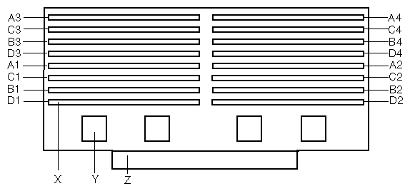
X. One of sixteen DIMM sockets
Y. One of four Memory Address Data Paths (MADPs)
Z. Memory Expansion Card Connector (MECC)
Each slot is identified by another notation. Sockets A1 through A4 are identified as J1 through J4 respectively. Sockets B1 through B4 are identified as J5 through J8. Sockets C1 through C4 are identified as J9 through J12. Sockets D1 through D4 are identified as J13 through J16.
Some operating systems and application programs use base memory while others use both conventional and extended memory. Examples are:
Base memory: Microsoft MS-DOS, IBM OS/2, Microsoft Windows NT, and various UNIX systems
Conventional and extended memory: IBM OS/2, Microsoft Windows NT, and various UNIX systems
MS-DOS does not use extended memory; however, some MS-DOS utility programs like RAM disks, disk caches, print spoolers, and windowing environments use extended memory for better performance.
The BIOS automatically detects, sizes, and initializes the memory array, depending on the type, size, and speed of the installed DIMMs, and reports memory size and allocation to the system via configuration registers.
The National PC97317VUL Super I/O Plug and Play Compatible with ACPI Compliant Controller/Extender device supports two serial ports, one parallel port, a diskette drive, and a PS/2-compatible keyboard and mouse. The system provides the connector interface for each port.
Both serial ports can be relocated. Each serial port can be set to one of four different COMx ports, and each can be enabled separately. When disabled, serial port interrupts are available to add-in boards.
The baseboard provides a 25-pin Parallel Port connector. The SIO chip provides an IEEE 1284-compliant, 25-pin, bi-directional parallel port. BIOS programming of the SIO registers enable the parallel port and determine the port address and interrupt. When disabled, the interrupt is available to add-in cards.
The baseboard has eight slots for PCI add-in boards supported by three PCI bus segments called PCI-A, PCI-B, and PCI-C. There are two slots on PCI-A, four slots on PCI-B, and two slots on PCI-C. PCI-C supports half-length boards (5.6 inches to 6.3 inches) only; the other slots support full-length boards.
The two slots for the PCI bus segment PCI-C consume a maximum of 375 mA of standby current on a 3.3 V Aux power line. The remaining six slots do not have any 3.3 V Aux capabilities.
Both PCI segments A and B allow you to add, remove, or replace PCI add-in boards installed in their slots without interrupting normal operation or powering down the system. To use this PCI Hot-Plug (PHP) feature, a server system requires PCI Hot-Plug software and PCI Hot-Plug capable add-in boards. PCI Hot-Plug software usually is a driver loaded for a specific operating system.
 | Note: At this time, the Linux operating system does not support use of the PCI Hot-Plug (PHP) feature. If you are running Linux, your system must be turned off before installing or removing PCI boards. Windows 2000 requires drivers that are PHP compatible in order to use the PHP feature. |
Each Hot-Plug PCI slot has two LEDs. The green LED indicates the state of power on for each slot. The amber LED indicates an error condition with that slot.
The table below summarizes typical LED states that you may encounter during a system's operation.
Table 2-2. Slot State Indicators
LED State | Status |
|---|---|
Green On Amber Off | The slot is on and functioning normally. |
Green On Amber On | The slot is on and the card requires attention. |
Green Off Amber On | The slot is off and the card in the slot requires attention. |
Green blinking Amber Off | Slot power is transitioning from either ON to OFF or OFF to ON. |
Off | The slot is powered off. |
33 or 66 MHz bus speed
32-bit or 64-bit memory addressing
3.3 V or 5 V signaling environment
Independent bus structure supports transfers up to 1.2 GB/sec.
8-, 16-, 32-, or 64-bit data transfers
Plug-and-Play ready
Parity enabled
| Note: At this time, the Linux operating system does not support use of the PCI Hot-Plug (PHP) feature. If you are running Linux, your system must be turned off before installing or removing PCI boards. Windows 2000 requires drivers that are PHP compatible in order to use the PHP feature. |
The DesotoE2 Hot-Plug PCI controller is a 32-bit PCI bus agent that operates at either 33 or 66 MHz. The PCI controller manages PHP functionality for the PCI segment it resides on. There is a DesotoE2 controller on PCI segments A and B. The DesotoE2 PHP controller is:
ACPI compliant
Compatible with Compaq's PHP controller design
Supports either a 3.3 V or 5 V PCI bus
The DesotoE2 is responsible for:
Managing power application and removal to individual slots
Properly resetting newly added PCI boards prior to bringing the board online
Managing connection and disconnection of the PCI signals between the PCI bus and the add-in board
Managing seamless addition and removal of individual PCI add-in boards without impacting bus functionality
The Open South Bridge (OSB4) acts as a PCI-based fast IDE controller. The controller supports programmed I/O and bus master transfers. While the OSB4 supports two IDE channels, the baseboard uses only the primary IDE channel and provides a single 40-pin IDE connector.
The baseboard provides a dual external USB connector for the back panel of a server system. The connector is defined by the USB Specification, Revision 1.0. Both ports function identically with the same bandwidth.
The baseboard supports a 10BASE-T/100BASE-TX network subsystem based on the Intel 82559 Fast Ethernet Multifunction PCI/CARDBus controller. The Intel 82559 controller is a highly integrated PCI LAN controller in a 196-pin Ball Grid Array (BGA) supporting 10 or 100 Mbps fast Ethernet networks.
Supported network features include:
Glueless 32-bit PCI Bus Master Interface compatible with the PCI Local bus Specification
82596-like chained memory structure with improved dynamic transmit chaining for enhanced performance
Programmable transmit threshold for improved bus utilization
Early receive interrupt for concurrent processing of receive data
On-chip counters for network management
Auto-detect and auto-switching for 10 or 100 Mbps network speeds
Support for both 10 and 100 Mbps networks
Integrated physical interface to TX magnetics
The magnetics component terminates the 100BASE-TX connector interface and a flash device stores the network ID
The baseboard provides an ATI Rage IIc VGA Graphics Accelerator, along with video Synchronous Graphics RAM (SGRAM) and support circuitry for an embedded Super VGA (SVGA) video subsystem. The ATI Rage IIc chip contains an SVGA video controller, clock generator, BitBLT engine, and a RAM digital-to-analog Converter (RAMDAC) in a 208-pin PQFP. One 256K x 32 SGRAM chip provides 2 MB of 10-ns video memory. The baseboard does not support adding video memory to the system. The SVGA subsystem supports a variety of modes, up to 1600 x 1200 resolution, or up to 16.7 M colors.
The SVGA subsystem also supports analog VGA monitors, single- and multi-frequency, interlaced and non-interlaced, up to 100 Hz vertical retrace frequency. The baseboard provides a standard 15-pin VGA connector and video blanking logic for server management console redirection support.
Depending on the environment, the controller displays up to 16.7 M colors in some video resolutions.
The baseboard includes two SCSI controllers. A dual function SCSI controller (Adaptec AIC-7899) is on the PCI-B bus, and a PCI wide SCSI controller (Adaptec AIC-7880) is on the PCI-C bus.
The Adaptec AIC-7899 SCSI controller contains two independent SCSI channels that share a single PCI bus master interface as a multifunction device, packaged in a 352-pin ball grid array (BGA). Internally, each channel is identical, capable of operations using either 16-bit Single-Ended (SE) or Low Voltage Differential (LVD) SCSI providing 40 MBps (Ultra-wide SE), 80 MBps (Ultra 2), or 160 MBps (Ultra 160).
Both channels attach to 68-pin 16-bit differential SCSI connector LVD interfaces. Each channel has its own set of PCI configuration registers and SCSI I/O registers. As a PCI bus master, the AIC-7899 controller supports burst data transfers on PCI up to the maximum rate of 266 MBps using on-chip buffers.
The Adaptec AIC-7880 controller contains a single SCSI channel with full-featured PCI bus master interface in a 160-pin Plastic Quad Flat Pack (PQFP). The controller supports either 8- or 16-bit Fast SCSI providing 10 MBps or 20 MBps (Fast-10) throughput, or Fast-20 SCSI that can burst data at 20 MBps or 40 MBps. As a PCI 2.1 bus master, the AIC-7880 controller supports burst data transfers on PCI up to the maximum rate of 133 MBps using the on-chip 256-byte FIFO.
The AIC-7880 implementation offers 8-bit or 16-bit SCSI connectors and operation at data transfer rates of 10, 20, or 40 MBps. The AIC-7880 controller also offers active negation outputs, controls for external differential transceivers, a disk activity output, and a SCSI terminator power-down control. Active negation outputs reduce the chance of data errors by actively driving both polarities of the SCSI bus, avoiding indeterminate voltage levels and common-mode noise on long cable runs. The SCSI output drivers can directly drive a 48-mA single-ended SCSI bus with no additional drivers. The SCSI segment can support up to 15 devices.
The AIC-7880 controller can be used as an 8-bit controller via the narrow, 50-pin connector and as a 16-bit controller via the wide, 68-pin connector. As a result, the AIC-7880 controller is not always at one end of the SCSI bus, and termination is controlled through some simple circuitry. The circuitry senses whether there is a device attached through the narrow 50-pin connector or the wide 68-pin connector. When there are devices attached to both connectors, the termination is on for the upper 8 bits of data and the parity bit associated with these data lines. All other signals are not terminated on board and are terminated by the devices attached through the connector. When there is a device attached to only one connector (either wide or narrow), all on-board termination is on.
IDE is a 16-bit interface for intelligent disk drives with AT disk controller electronics onboard. The Open South Bridge (OSB4) acts as a PCI-based fast IDE controller. The device controls:
PIO and IDE DMA/bus master operations
Mode 4 timings
Transfer rates up to 33 MBbs.
Ultra DMA 33 capacity
Buffering for PCI/IDE burst transfers
Master/slave IDE mode
Up to two drives for one IDE channel
Note: An IDE signal cable can be connected up to the IDE connector on the baseboard. However, the maximum length of the cable is 18 inches. The cable supports up to two devices, one at the end of the cable and the other six inches from the end.
The PS/2-compatible keyboard and mouse connectors are mounted in a single-stacked housing with the mouse connector over the keyboard. Externally, they appear as two connectors.
The user can plug in the keyboard and mouse to either connector before powering up the system. The BIOS detects these and configures the keyboard controller accordingly.
The keyboard controller is functionally compatible with the Intel 8042A micro controller. The system can be locked automatically if no keyboard or mouse activity occurs for a predefined length of time, if specified through the SSU. Once the inactivity (lockout) timer has expired, the keyboard and mouse do not respond until the previously stored password is entered.
Server management features are implemented using one micro controller called the Baseboard Management Controller (BMC).
The BMC and associated circuitry are powered from 5 V standby, which remains active when system power is switched off. The BMC is IPMI 1.0 compliant.
The primary function of the BMC is to autonomously monitor system platform management events and log their occurrence in the nonvolatile System Event Log (SEL). The BMC is compliant to the Intelligent Platform Management Interface Specification, Version 1.0. These events include over-temperature and over-voltage conditions, fan failure, or chassis intrusion. While monitoring, the BMC maintains the nonvolatile Sensor Data Record Repository (SDRR), from which run-time information can be retrieved. The BMC provides an interface to SDRR information, so software running on the server can poll and retrieve the current status of the platform. A shared register interface is defined for this purpose.
Field service personnel can retrieve SEL contents after system failure for analysis by using system management tools like Intel LANDesk Server Manager, Intel Server Control (ISC), or Direct Platform control (DPC). Because 5 V standby provides power the BMC, SEL (and SDRR) information is also available via the interperipheral management bus (IPMB). During monitoring, the BMC performs the following functions:
Baseboard temperature and voltage monitoring
Processor presence monitoring and FRB control
Baseboard fan failure detection and indicator control
SEL interface management
Sensor Data Record Repository (SDRR) interface management
SDR/SEL timestamp clock
Baseboard Field Replaceable Unit (FRU) information interface
System management watchdog timer
SMI/NMI Status Monitor
Front panel NMI handling
Event receiver
IPMB Management Controller Initialization Agent
Secure mode control, front panel lock/unlock initiation, and video blank and diskette write protect monitoring and control
ACPI Support
Direct Platform Control (DPC) support
Platform Event Paging (PEP) / Platform Event Filtering (PEF)
Power distribution board monitoring
Speaker beep capability. When the system is powered up, this capability is used to indicate conditions such as “empty processor slot”
Pentium III Xeon processor SEEPROM interface for Processor Information ROM (PIROM) and Scratch EEPROM access
Processor temperature monitoring
Hot-Plug PCI slot status reporting
Processor bus speed setting
Chassis fan failure light control
Chassis power fault light control
Chassis power light control
The SSU provides a number of security features to prevent unauthorized or accidental access to the system. Once the security measures are enabled, access to the system is allowed only after the user enters the correct password(s). For example, the SSU allows you to:
Enable the keyboard lockout timer so the server requires a password to reactivate the keyboard and mouse after a specified time-out period of 1 to 120 minutes
Set and enable administrator and user passwords
Set secure mode to prevent keyboard or mouse input and to prevent use of the front panel reset and power switches
Activate a hot key combination to enter secure mode quickly
Disable writing to the diskette drive when secure mode is set
If a user password is set and enabled, but an administrator password is not set, a user password must be entered to boot the system and run the SSU.
If both a user and administrator password are set:
Enter either one to boot the server and enable the keyboard and mouse
Enter the administrator password to access the SSU or BIOS Setup to change the system configuration
Configure and enable the secure boot mode by using the SSU. When secure mode is in effect:
The system can boot and the operating system runs, but the user password must be entered for a user to use the keyboard or mouse
The system cannot be turned off or reset from the front panel switches
Secure mode has no effect on functions enabled via the Server Manager Module or power control via the real-time clock (RTC).
Taking the system out of secure mode does not change the state of system power. That is, if you press and release the power switch while secure mode is in effect, the system will not power off when secure mode is later removed. However, if the front panel power switch remains depressed when secure mode is removed, the system will power off.
Table 2-3 lists the software security features and describes what protection each offers. In general, to enable or set the features listed here, the SSU must be run and configured with the Security Menu (described in this manual in “Security Menu” in Chapter 3.) The table also refers to other SSU menus and to the Setup utility. For greater detail, see “Security Menu” in Chapter 3.
Table 2-3. Software Security Features
Feature | Description |
|---|---|
Secure mode | How to enter secure mode: Setting and enabling passwords automatically places the system in secure mode. If a hot key combination is set (through the SSU or Setup), the system can be secured simply by pressing the key combination. This means that the user does not have to wait for the inactivity time-out period. When the system is in secure mode: The server can boot and run the operating system, but mouse and keyboard input is not accepted until the user password is entered. At boot time, if a CD is detected in the CD-ROM drive or a diskette in drive A, the system prompts for a password. When the password is entered, the server boots from CD or diskette and disables the secure mode. If there is no CD in the CD-ROM drive or diskette in drive A, the server boots from drive C and automatically goes into secure mode. All enabled secure mode features go into effect at boot time. To leave secure mode, enter the correct password(s). |
Disable writing to diskette | In secure mode, the server will not boot from or write to a diskette unless a password is entered. To set this feature, use the SSU Security Subsystem Group. To write protect access to diskette whether the server is in secure mode or not, use the Setup main menu, Floppy Options, and specify Floppy Access as read only. |
Disable the power and reset buttons | Power and reset buttons are always disabled when the server is in secure mode. |
Set a time out period so that keyboard and mouse input are not accepted.
Also, screen can be blanked, and writes to diskette can be inhibited | Specify and enable an inactivity time-out period of from 1 to 120 minutes. If no keyboard or mouse action occurs for the specified period, attempted keyboard and mouse input will not be accepted. The monitor display will go blank, and the diskette drive will be write protected (if these security features are enabled through Setup or the SSU and using onboard video). To resume activity, enter the user password. |
Control access to using the SSU: set administrative password | To control access to setting or changing the system configuration, set an administrative password and enable it through Setup or the SSU. If both the administrative and user passwords are enabled, either can be used to boot the server or enable the keyboard and/or mouse, but only the administrative password will allow Setup and the SSU to be changed. To disable a password, change it to a blank entry or press Ctrl-D in the Change Password menu of the Administrative Password Option menu found in the Security Subsystem Group. If you cannot access Setup or the SSU to clear the password, change the Clear Password jumper. See “CMOS Clear Jumper” in the SGI 1450 Server Maintenance Guide. |
Control access to the system other than SSU: set user password | To control access to using the system, set a user password and enable it through Setup or the SSU. To disable a password, change it to a blank entry or press Ctrl-D in the Change Password menu of the User Password Option menu found in the Security Subsystem Group. If you cannot access Setup or the SSU to clear the password, change the Clear Password jumper. See “CMOS Clear Jumper” in the SGI 1450 Server Maintenance Guide. |
Boot without keyboard | The system can boot with or without a keyboard. During POST, before the system completes the boot sequence, the BIOS automatically detects and tests the keyboard if it is present and displays a message. There is no entry in the SSU to enable or disable a keyboard. |
Specify the boot sequence | The sequence specified on the menu in the SSU MultiBoot Group will determine the boot order. If secure mode is enabled (a user password is set), then the user is prompted for a password before the server fully boots. If secure mode is enabled and the Secure Boot Mode option is also enabled, the server fully boots but requires a password before accepting any keyboard or mouse input. |