This chapter provides a description of the external and internal structure of the SGI 1450 server.
The following sections are covered:
The SGI 1450 server is designed to be either mounted in a standard 19-inch rack (rack mode) or standing upright (pedestal mode). Table 1-1 shows the physical specifications for the SGI 1450 server in rack mode.
For instructions on mounting the SGI 1450 server in a 19-inch rack, see the SGI 1450 Server Mounting Instructions.
Table 1-1. SGI 1450 Server Physical Specifications
Specification | Rack Mode |
|---|---|
Height | 4u (7 inches) |
Width | 17.5 inches (44.5 cm) |
Depth | 26.5 inches (67.3 cm) |
Weight | 57 lbs. (26 kg), minimum configuration 88 lbs. (40 kg), maximum configuration |
Required front clearance | 3 inches (inlet air temperature <35 ˚C / 95 ˚F) |
Required rear clearance | 6 inches (no airflow restriction allowed) |
Required side clearance | 1 inch |
Figure 1-1 shows a SGI 1450 server in rack-mountable configuration.

A. Top Cover. The top cover protects the contents of the chassis.
B. Front Cover. The front cover protects the peripheral devices.
C. Front Bezel Door. When this door is open, you can access hard drives and peripheral devices.
D. Front Bezel.
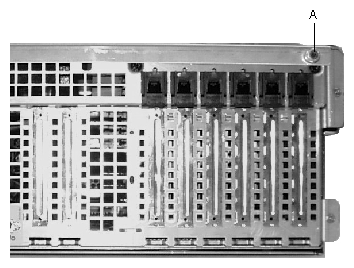
The chassis has two covers: a front cover and a top cover. The front cover is secured by screws and should be removed only by a qualified service technician. The top cover is secured by thumbscrews and provides user access to hot-pluggable PCI components. One of two thumbscrews is noted by “A” in Figure 1-2.
 | Note: At this time, the Linux operating system does not support use of the PCI Hot-Plug (PHP) feature. If you are running Linux, your system must be turned off before installing or removing PCI boards. Windows 2000 requires drivers that are PHP compatible in order to use the PHP feature. |
A bezel snaps on to the front of the chassis and allows adequate airflow to cool the system components. The door in the bezel provides user access to hard drives and the peripheral bay.
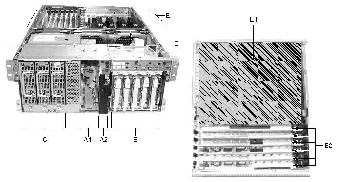
Figure 1-3 gives an overhead view of the system with the top cover, front cover, and front bezel removed.
 | Warning: The total power requirement for the SGI 1450 server exceeds the 240 VA energy hazard limit that defines an operator-accessible area. Only qualified service technicians should access the processor, memory, power subsystem, and non hot-plug/hot-swap areas of the baseboard. |
Table 1-2 summarizes the SGI 1450 server chassis features, using the labels provided in Figure 1-3.
Table 1-2. Chassis Feature Summary
Feature | Description |
|---|---|
A. Peripheral Bay [A1 and A2] | A peripheral bay in the front of the system has a 5.25-inch device bay and a media bay. |
A1. Peripheral Bay: Device Bay | The device bay can hold a 5.25-inch CD-ROM or DAT device. |
A2. Peripheral Bay: Media Bay | The media bay holds a 0.5-inch slim-line floppy drive and a 0.5-inch slim-line CD-ROM drive. |
B. Hard Drives | The hard drive bay supports up to five 1.0-inch hot-swap Ultra 160 SCSI hard drives. If the operating system supports hot-swapping of hard drives, these drives can be changed without shutting down the server. |
C. Power Subsystem | Installed: A power subsystem bay that supports up to three 350-watt power supply modules in a (2+1) redundant configuration. The power subsystem can only be accessed by qualified service technicians. |
D. Cooling | Installed: Fan board assembly and six fans in a redundant (5+1) fan array. The fans cool the baseboard and other components. In a 5+1 configuration, a failed fan may be removed and replaced without shutting down the server. This process is called hot-swapping. Hot-swapping fans should only be performed by a qualified service technician. |
E. Electronics Bay (E-Bay) | The E-Bay contains the baseboard. The baseboard has the following major components: Up to four Intel Pentium III Xeon processors Server Set III HE chipset Up to sixteen PC/100-compliant Registered ECC SDRAM memory modules, allowing up to 16 gigabytes of Error Checking and Correcting (ECC) Synchronous Dynamic RAM 32-bit, 33 MHz, 5V PCI slots and several embedded devices 64-bit, 66/33 MHz, 3.3V hot-plug PCI slots and one embedded device 64-bit, 33 MHz, 5V hot-plug PCI slots and three embedded devices ISA bus segment with three embedded devices Two externally accessible USB ports One IDE connector, supporting up to two ATA33 compatible devices With the exception of the hot-plug PCI cards, the E-Bay can only be accessed by qualified service technicians. |
E1. E-Bay (Overhead View) | An overhead view of the E-Bay |
E2. Hot-plug PCI Slots | Six hot-plug PCI slots located within the E-Bay NOTE: At this time, the Linux operating system does not support use of the PCI Hot-Plug (PHP) feature. If you are running Linux, your system must be turned off before installing or removing PCI boards. Windows 2000 requires drivers that are PHP compatible in order to use the PHP feature. |
The chassis contains one peripheral bay for CD-ROM, DAT, and floppy drives. The peripheral bay contains two smaller bays: a device bay and a media bay.
The chassis contains one hard drive bay. The hard drive bay can accommodate up to five 3.5-inch by 1.0-inch hot-swap Ultra 160 SCSI SCA hard disk drives
Opening the front bezel door provides user access to the hard drives. As part of the hot-swap implementation, each hard drive requires a hard drive carrier. When you remove a hard drive from the system, you remove both the carrier and the hard drive. The drive is attached to the carrier by four screws. The carrier locks into the hard drive bay by a locking handle. Figure 1-4 shows the orientation of the drive in the carrier. The carrier is upside down in this figure.
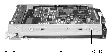
A. Hard Drive Carrier
B. Two (of four) Fasteners Used to Attach Drive to Carrier
C. Hard Drive
D. Connector
E. Locking Handle
Each hard drive is connected to an Ultra 160 SCSI hot-swap backplane. The backplane provides industry-standard 80-pin SCA-2 connectors for each hard drive and accepts 10,000 RPM or slower drives that consume up to 23 watts of power. If another type or a slower Ultra 160 SCSI SCA drive is installed, make sure that the drive meets these backplane and carrier requirements.
An LED above each hard drive displays the status of that hard drive. Table 1-3 shows the hard drive LED state status.
Table 1-3. Hard Drive LED State Status
LED State | Status |
|---|---|
Solid green | The hard drive is present and powered on. |
Flashing green | The hard drive is active. |
Solid yellow | There is an asserted fault status on the hard drive. |
Flashing yellow | A rebuild of the hard drive is in progress. |
Off | The hard drive is not powered on. |
The SGI 1450 server uses a universal input-switching power subsystem (PSBS). This subsystem provides up to 630 watts DC. The subsystem also minimizes the RMS current drawn from each AC line by providing power-factor corrected AC input. The chassis can be configured with one, two, or three 350-watt power supply modules, where each is designed to minimize electromagnetic interference (EMI) and radio frequency interference (RFI).
| Warning: The total power requirement for the SGI 1450 server exceeds the 240 VA energy hazard limit that defines an operator-accessible area. Only qualified service technicians should access the processor, memory, power subsystem, and non hot-plug/hot-swap areas of the baseboard. |
The power subsystem consists of a power subsystem bay, with up to three power supply modules. The power subsystem bay contains a power distribution board, which manages the power delivered by all functional power supplies.
The power subsystem can operate in either a nonredundant or redundant manner. Nonredundant operation means that you are using only one or two power supply modules. If a power supply module ceases to function normally, the server system cannot function properly, if at all. A minimal configuration supported by one power supply module is one processor, four memory DIMMs, one hard drive slower than 10,000 RPM, one floppy drive, and one CD-ROM.
The SGI 1450 server uses a redundant (2+1) power subsystem. To form a (2+1) redundant power subsystem, the subsystem parallels the DC output of one power supply module with one or two other modules. If one module ceases to function normally, the remaining modules provide power to the server system and the system continues to function properly. Two power supply modules are required to provide power to a fully configured SGI 1450 server. The third module provides redundancy. A fully configured system includes four processors, 8 GB of memory, one floppy drive, one CD-ROM, five hard drives, and eight PCI add-in boards.
The SGI 1450 server uses up to six fans mounted in a fan board assembly in the middle of the chassis between the E-Bay and peripheral device bays. The six fans are noted by “A” in Figure 1-5.
| Warning: The total power requirement for the SGI 1450 server exceeds the 240 VA energy hazard limit that defines an operator-accessible area. Only qualified service technicians should access the processor, memory, power subsystem, and non hot-plug/hot-swap areas of the baseboard. |
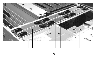
The cooling system can operate in either a non redundant configuration or a redundant configuration. A non redundant configuration includes just three fans. If any one of these three fans ceases to function normally, environmental conditions within the chassis may exceed the environmental regulations in this guide and the chassis may not function normally. Three fans support any system configuration but without fan redundancy.
The SGI 1450 server uses all six fans to form a redundant cooling system. If one of the six fans ceases to function normally, the remaining five fans adequately cool the system. Using six fans supports any configuration up to the maximum configuration.
Air flows in through the front bezel over the power subsystem bay, the peripheral bay, and the hard drive bay. The air then passes through the fan board assembly and to the baseboard. Finally, the air exhausts through the rear and left side of the chassis.
Individual fan status indicators are located on the fan board mounted in the fan board assembly. Fan failure is also indicated by the general fault LED located at the front of the chassis.
 | Caution: The top cover must be on the system for proper cooling. |
Figure 1-6 shows the front panel controls and indicators.
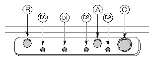
The following front controls and indicators are shown in Figure 1-6.
A. Power on/off button: If you press this button when the system is off, you turn on the power subsystem. If you press this button when the system is in sleep state, you activate it. If you hold down the button for more than 4 seconds, you override the ACPI mode and the power is turned off.
B. Reset button: If you press this button, you reset the system. If you hold down this button for 4 seconds or more, push on the power button, and then release both the reset and power buttons within one second of each other, the CMOS will be cleared.
| Caution: The CMOS should be cleared only if it has been corrupted. |
C. Sleep button: If the operating system supports ACPI and you press this button, the operating system goes into sleep state (S1). If you press this button during sleep state, the operating system becomes active. This system does not have a service mode.
D. Front panel LEDs from left to right:
D0. General System Fault LED: Yellow indicates a system failure.
D1. NIC activity LED: Green indicates NIC activity.
D2. HDD activity LED: Green indicates any system hard drive activity.
D3. Main Power LED: Solid green indicates the presence of DC power in the server.
Flashing green indicates that the system is in ACPI sleep mode.
Figure 1-7 shows a detailed view of the rear panel I/O ports and features.
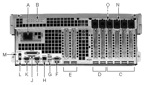
A. AC input power connector
B. External SCSI connector ports
C. Hot-plug 64-bit, 33 MHz PCI add-in board slots
D. Hot-plug 64-bit, 66/33 MHz PCI add-in board slots
E. Non-hot-plug 32-bit, 33 MHz PCI add-in board slots
These slots can also accept an Intelligent Chassis Management Bus (ICMB) SEMCONN 6-pin connector in/out
F. Video connector
G. USB ports 0 (upper) and 1 (lower), 4-pin connectors
H. NIC RJ45 connector
I. Serial port 2 (COM1), 9-pin RS-232 connector
J. IEEE 1284 compliant, 25-pin bi-directional parallel connector
K. Serial port 1 (COM1), 9-pin RS-232 connector
L. PS/2-compatible keyboard connector
M. PS/2-compatible mouse connector
N. HW push button
O. PCI green and amber LEDs inside the chassis