To allow graphical applications to behave properly in immersive environments, you must specify the physical layout of the display area and the relative position of the observer. MPK allows you to do this by extending the notion of the viewing frustum in a graphical application. This chapter uses the following sections to describe this task:
As described in Chapter 6, “Configuration File Format”, MPK expects a frustum description as part of the channel data structure.
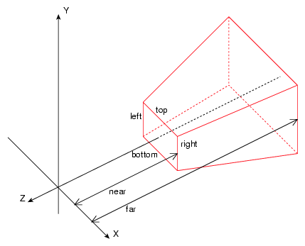
Figure 3-1 depicts an orthographic frustum.
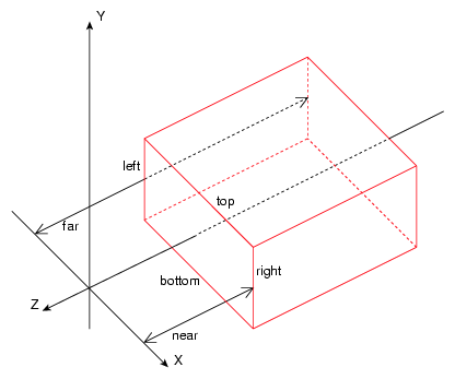
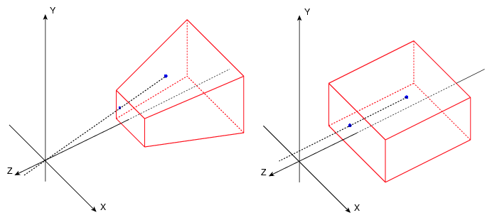
Figure 3-2 depicts a perspective frustum.
Note the following about the two frusta:
Both are totally defined by the near, far, left, right, top, and bottom distances and the assumption of having the eyepoint at the origin and the near and far distances for each defined with respect to the Z axis. The OpenGL near and far planes are always parallel to each other and perpendicular to the Z axis. An off-axis OpenGL frustum corresponds to the case where the near-plane rectangle is not centered around the Z axis. This is generally the case in immersive environments. See Figure 3-4 for an example of an off-axis frustum.
Both final images (pixmaps) correspond to the near plane image.
In the case of a perspective frustum and as illustrated in Figure 3-3, the near plane intersection with a line from the eyepoint to the scene graph object defines the pixel color. Distant objects appear smaller in the pixmap.
In the case of an orthographic frustum and as illustrated in Figure 3-3 also, the near plane intersection with a line parallel to the Z axis and extending to the scene graph object defines the pixel color. The size of objects is preserved in the orthographic view.
Given these definitions of a pixmap, you control the appearance of the pixmap by selecting the type of frustum and setting the frustum parameters (near, far, left, right, top, and bottom).
In non-immersive environments, the location of the eyepoint and monitor screen in the real world is arbitrary and you do not need to account for it.
In non-immersive environments, you have arbitrary (usually symmetric) left, right, top, and bottom parameters.
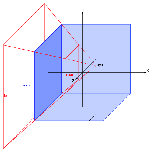
In an immersive environment, you need to establish the location of the eyepoint and the monitor in real-world coordinates; they are no longer arbitrary. The monitor screen is now a see-through glass window into the scene graph. Figure 3-4 illustrates the new effective frustum, which is completely determined by the following specifications:
near and far distances
Real-world eyepoint location
Real-world screen position
MPK expects the dimensions (position and size) of the screen to be specified as part of the associated channel's data structure—that is, as if the screen itself was a 3D object in your database. You must specify the same units and coordinate system as will be used by the application when drawing the database.
MPK allows the eyepoint location to be specified using a simple programming interface. The application needs only to provide real-world information about the position and attitude of the viewer. MPK then transparently adapts its left- and right-eye frustum computation.
MPK provides two modeling methods to describe your projection system:
Wall model (Cartesian coordinates)
Projection model (polar/cylindrical/spherical coordinates)
The most appropriate modeling method usually corresponds to the one requiring fewer manual computations in order to describe the geometry of your environment.
Wall model coordinates are well-suited to describe projection screens that are arranged as flat screens, such as in a TANORAMA POWERWALL or TAN HOLOBENCH facility. To describe a projection screen using the wall model, you need to provide the Cartesian coordinates of three of its vertices using object data coordinates (x',y',z'):
Bottom-left vertex
Bottom-right vertex
Top-left vertex
Example 3-1 shows an example of using wall model coordinates in a configuration file for a wall that is 3 meters by 3 meters and 1.5 meter in front of the viewer. The example assumes that the application expects the coordinates to be specified in meters:
Example 3-1. Specifying Wall Model Coordinates
#  a 3m x 3m screen located 1.5 m in front of the viewer
#
wall {
    bottom_left      [ –1.5, –1.5, –1.5 ]
    bottom_right     [  1.5, –1.5, –1.5 ]
    top_left         [ –1.5,  1.5, –1.5 ]
}
|
Projection model coordinates are well-suited to describe projection screens that are in a curved or tilted arrangement, such as in the traditional three-pipe SGI Reality Center, the V-Dome, and the Responsive Workbench facilities. To describe a projection screen using the projection model, you need to provide the following information:
Origin in Cartesian coordinates,using object data coordinates (x',y',z')
Euler angles of the projection plane—that is, the counter-clockwise rotation around the Y axis (heading), X axis (pitch), and Z axis (roll) viewed from the positive side of the axis
Distance of the projection plane from the origin in the application's measurement units
Horizontal and vertical fields of view (FOV)
Example 3-2 shows an example of using projection model coordinates in a configuration file. The configuration is a three-channel, hemi-cylindrical Reality Center with the following dimensions:
For each specified channel, the resulting projection area corresponds to the rectangle that would be produced by a hypothetical projection system located at origin with the orientation characterized by the hpr angles and projecting orthogonally onto a wall situated at distance.
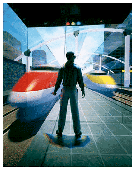
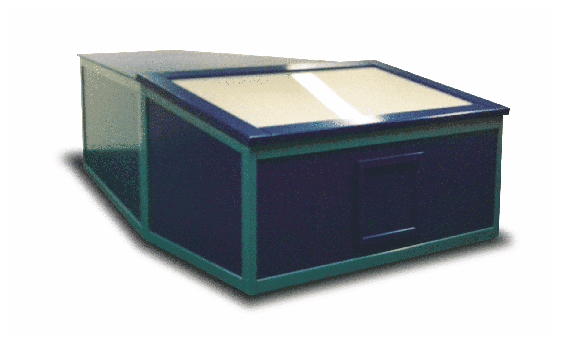
There are a variety of commercial products that illustrate the most appropriate choice for the two modeling methods. Figure 3-5 and Figure 3-6 illustrate flat-screen arrangements that are ideal for the use of the wall model.
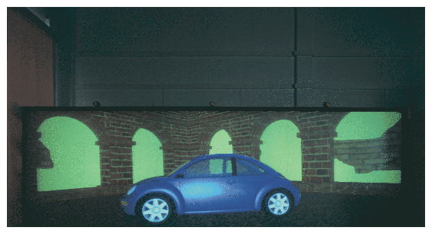
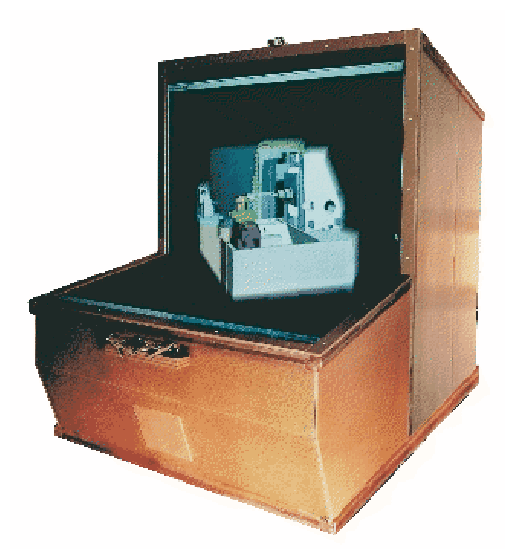
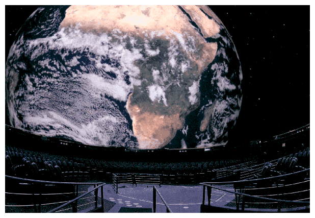
Figure 3-7, Figure 3-8, and Figure 3-9 illustrate curved or tilted arrangements of projection screens and are ideal for the use of the projection model.