This chapter describes how to use the features of the Silicon Graphics MultiLink. The on-screen display provides access to the flat panel display controls.
The five buttons on top of the MultiLink, shown in Figure 2-1, interact with the on-screen display.
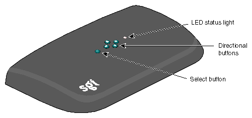
You use the five buttons on top of the MultiLink to:
Start and stop the display of the on-screen display (the select button)
Choose a menu (right and left directional buttons)
Choose a menu item (up and down directional buttons)
Change the mode focus from selecting menu items to changing display settings (the select button)
Change settings (directional buttons)
Save settings and exit (the select button)
To display the on-screen display, press the select button.
Figure 2-2 shows that the layout of the on-screen display includes:
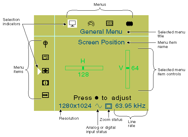
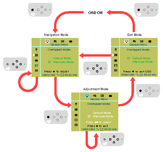
The following scenario explains how to use the five buttons on top of the MultiLink with the on-screen display. Figure 2-3 shows a flowchart of the actions described in the following steps.
To display the on-screen display, press the select button on top of the MultiLink.
To choose a menu, press the right or left directional button.
Notice that each time you press one of these buttons:
The menu icon highlight moves left or right, corresponding to the directional button you push, showing which menu is selected.
The title of the menu, located just under the menu icons, changes according to the menu selected.
The menu items in the left vertical column change according to the menu selected
To choose a menu item in the selected menu, press the up or down directional button.
Notice that each time you press one of these buttons:
The menu item selection indicator moves up or down to show you which menu item is selected.
The name of the menu item, located just under the menu title, changes according to the menu item selected.
The menu item controls in the center of the on-screen display, change according to the menu item selected.
To use the menu item controls of the selected menu item:
Press the select button.
Notice that the menu icon highlight and the menu item selection indicator turn gray and the items in the center of the on-screen display turn white to indicate the current selection. Now the directional buttons interact with the menu item controls instead of navigating through menus and menu items.
To change the menu item settings, press any of the directional buttons corresponding to the white arrows in the on-screen display window.

Note: The settings take effect immediately. Adjustments to the General Menu's Zoom, Overlapped Modes, and Force Detect menu items and the Advanced Menu's Factory Reset menu item will cause the screen to reset. Please refer to the descriptions of these menu items (which follow later in this chapter) for more details.
To end adjustment of the display controls, press the select button.
Notice that the menu icon highlight and the menu item selection indicator turn white while the menu item controls change color to indicate the current selection. The directional buttons now interact with the menu and menu item choices again.
You now have a choice for your next on-screen display action:
To use a different menu item or switch to another menu, use the directional buttons. Refer to steps 2 through 5 above.
Alternately, to exit the on-screen display immediately and save your settings, press the select button. You must press the select button before using any directional buttons or you will not exit the on-screen display.
Note: The on-screen display will automatically exit and save your settings after a period of inactivity. See the OSD Timeout menu item at “On-Screen Display Menu” for details.
Figure 2-3 shows in flowchart style how to use the select and menu buttons, as described in “How the On-Screen Display Works”. Darkened buttons on the keypad illustrations show how the state of the on-screen display changes according to user input. The Overlapped Modes menu item on the General Menu is shown as an example; all other menus and menu items also follow this flowchart.
On the bottom of the on-screen display shown in Figure 2-2 are four settings:
The resolution is expressed by the number of pixels drawn in the horizontal and vertical directions. For example, the highest resolution is 1600 X 1024, which means 1600 pixels are drawn on each horizontal line and 1024 horizontal lines are drawn.
Your video card sets the resolution. Consult your video card manual for instructions on changing the resolution.
The input to the MultiLink can be either analog or digital, as shown in Figure 2-4.
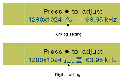
The sine wave icon shown in Figure 2-4 represents an analog input, the square wave icon represents a digital input.
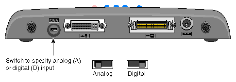
You specify the input by setting the analog and digital (A/D) input switch, shown in Figure 2-5, located on the back of the MultiLink.
| Note: For best results, set the analog and digital input switch position before turning on your computer. |
Line rate indicates the speed with which horizontal lines are drawn out of your video card to the MultiLink. Although the numbers you see for line rate will be close to the numbers pictured in this manual, they may not match exactly.
The refresh rate on the MultiLink is fixed at 60 Hz (except in special situations for legacy BIOS mode compatibility). If the refresh rate on the video card is incompatible with the refresh rate of the MultiLink, the LED on top of the MultiLink flashes yellow.
| Note: You cannot change the MultiLink's refresh rate value. |
The Zoom feature enables you to do the following (see Figure 2-6):
Maintain the proper aspect ratio of the image, which leaves black borders to the left and right of the image (Standard View)
Stretch the display so that the image fills the entire screen (Wide View)
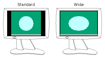
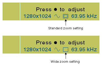
Figure 2-7 shows the icons for the Standard and the Wide zoom settings, respectively, that are found toward the bottom of the on-screen display.
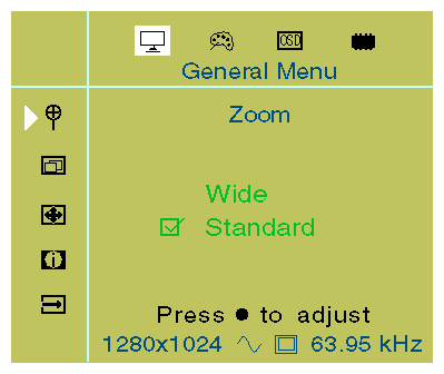
To set the zoom, use the Zoom menu item in the General menu, as shown in Figure 2-8.
This section explains the menu items in each of the on-screen display menus in the following sections:
The General Menu, shown in Figure 2-9, adjusts common flat panel display settings and user preferences.
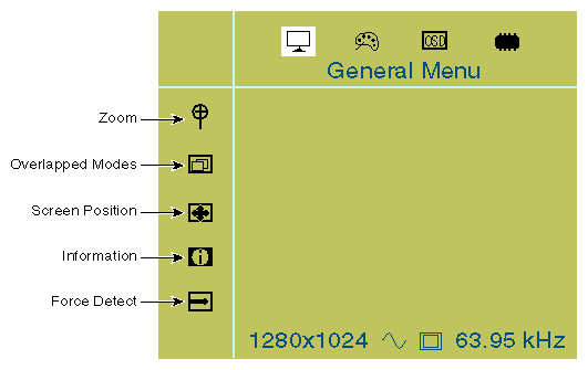
The General Menu has the following menu items:
Z oom—Changes the size of the displayed image, as described in “Zoom Status”, between Wide and Standard View.
O verlapped Modes—Chooses the correct resolution for display in special situations. Certain combinations of timing modes are indecipherable to the MultiLink. In such cases, you may need to override the MultiLink's settings through the Overlapped Modes menu item. Consult Table A-8 for a listing of the affected timing modes.
S creen Position—Changes the horizontal and vertical position of the entire image on the flat screen display.

Tip: This function is useful for fine-tuning image centering. I nformation—Provides general information about the MultiLink.
Force Detect—Causes the MultiLink to redetect and optimize the current screen image.
Tip: Use this feature to improve image quality. Note: Some user settings (Screen Position, Clock, and Phase) may be automatically adjusted during a Force Detect.
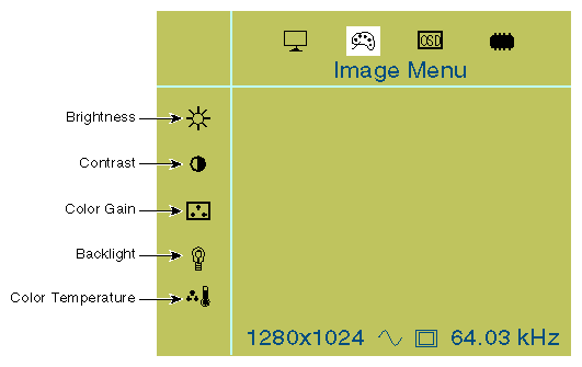
The Image Menu, shown in Figure 2-10, provides menu items that affect screen appearance parameters.
| Note: The following menu items described as “analog only” appear in the on-screen display only when the MultiLink is set for analog input as described in “Analog or Digital Input Status”. |
The Image Menu has the following menu items:
B rightness—(Analog only) Adjusts the overall brightness of the whites and the blackness of the blacks in all three color channels (R, G, and B) simultaneously. Also known as offset adjustment.
C ontrast—(Analog only) Simultaneously adjusts the intensity of all three color channels (R, G, and B) in the image.
Note: Adjusting contrast will override color gain settings. C olor Gain—(Analog only) Same as contrast adjustment except that red, green, and blue channels may be adjusted independently.
B acklight—Controls the overall intensity of the 1600SW backlighting system.
Note: The Backlight setting is independent of Brightness, which uses the analog interface. While the Brightness controls also alter the luminance of the screen image, they do so at the expense of reduced dynamic range (pixel colors themselves are shifted when Brightness is changed). Backlight adjustments do not cause pixel colors to change. Tip: Backlight adjustment may be preferable to Brightness when consistency in black level and grayscale response are important to the viewer. Note: Adjusting the Backlight setting will override the Color Temperature setting. C olor Temperature—Adjusts the backlight white point from warm, reddish-white to cool, bluish-white.
Note: Adjusting the Color Temperature resets the Backlight setting to a 50% level.
The On-Screen Display Menu, shown in Figure 2-11, affects the position, time-out setting, size, and language of the on-screen display.
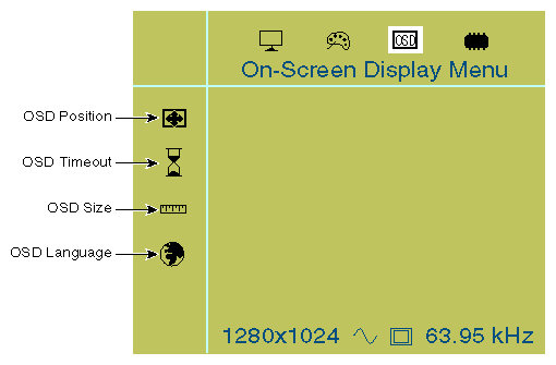
The On-Screen Display (OSD) Menu has the following menu items:
OSD Position—Moves the on-screen display vertically and horizontally.
Note: The on-screen display cannot be moved over to the left edge of the screen due to hardware limitations. OSD Timeout—Adjusts the time-out value between 5 and 30 seconds. Whenever the specified amount of time passes without any user interaction, the on-screen display disappears. To make it reappear, press the select button.
OSD Size—Adjusts the vertical size of the on-screen display box.
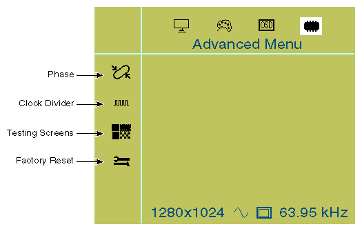
The Advanced Menu, shown in Figure 2-12, enables you to change settings that are less frequently adjusted.
| Note: The following menu items described as “analog only” appear in the on-screen display only when the MultiLink is set for analog input as described in “Analog or Digital Input Status”. |
The Advanced Menu has the following menu items:
P hase—(Analog only) Alters the phase setting used in the analog to digital conversion process. The MultiLink automatically adjusts clock phase upon detecting a new analog video mode. However, you may find that adjustments can improve image quality.
C lock Divider—(Analog only) Changes the clock divider setting used by the analog to digital conversion process. This parameter also influences image quality.
Tip: Clock Divider and Phase adjustments can be best performed by using a checkerboard or pinstripe background. If the clock divider is not correctly adjusted, vertical noise bars may appear. Adjust the clock divider setting until no noise bars are visible. Once the clock divider is correct, adjust the phase until you maximize image quality. Tip: If you cannot restore image quality after a Clock Divider or Phase adjustment, perform a Force Detect (General Menu) operation. Testing screens—Provides three alternate test patterns (horizontal lines, white field, and black field).
Note: This parameter resets to the “off” state whenever you exit the on-screen display or allow the on-screen display to timeout. F actory reset—Reverts all on-screen display settings for all video modes to their factory preset values. All user settings will be erased.