This chapter contains step-by-step procedures on how to disassemble the SGI 1100 server system for maintenance and troubleshooting.
 | Caution: The procedures contained in this chapter should be performed by a qualified service technician. Do not perform the procedures described in the following sections unless you are a qualified technician. |
The following sections are covered:
To disassemble the computer, you need the following tools and supplies:
Wrist grounding strap and conductive mat for preventing electrostatic discharge
Phillips screwdrivers

Note: The screws for the different components vary in size. During the disassembly process, group the screws with the corresponding components to avoid mismatches when putting back the components.
Before proceeding with the disassembly procedure, make sure that you do the following:
Turn off the power to the system and all peripherals.
Unplug the AC adapter and all power and signal cables from the system.
Do not remove a component from its antistatic packaging until you are ready to install it.
Wear a wrist grounding strap before handling electronic components. Wrist grounding straps are available at most electronic component stores.
This section covers the removal and installation of the chassis cover and the front panel.
| Note: A microswitch is located under the chassis cover. It detects whether the cover is removed or installed. |
Follow these steps to remove the chassis cover:
Turn off the power to the system unit and unplug all external cables.
Place the system unit on a flat, steady surface.
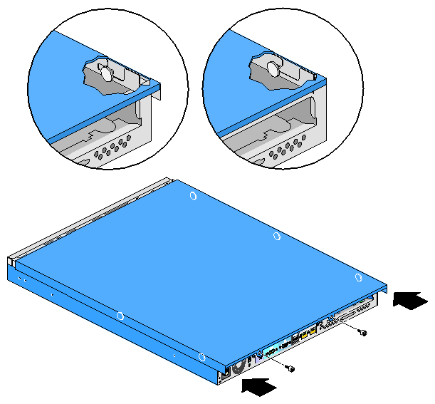
Release the two screw knobs at the rear of the chassis, as shown in Figure 2-1.
Slide the chassis cover towards the rear of the chassis about 1 inch (2.5 cm), as shown in Figure 2-1.
Lift the cover away from the chassis.

Follow these steps to install the chassis cover:
Place the system unit on a flat, steady surface.
Place the chassis cover on the chassis, so as to insert each of the six retaining pins into their slots as shown in Figure 2-2.
Ensure that all six retaining pins are fully engaged into their slots, and then slide the chassis cover toward the front of the system, as shown in Figure 2-2.
Tighten the two screw knobs to secure the chassis cover into place.
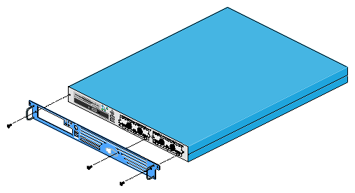
To remove the front panel, release the three screws and pull the front panel away from the chassis as shown in Figure 2-3.
To install the front panel, tighten the 3 screws to secure the front panel to the chassis.
This section covers the removal and installation of the link bar and the riser card.
Follow these steps to remove the link bar:
Remove the chassis cover as described in “Removing the Chassis Cover”.
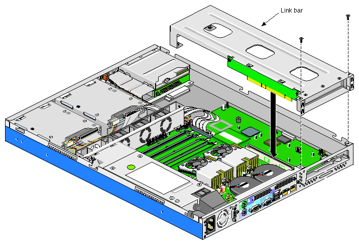
Remove two screws from the rear panel and pull the link bar away from the chassis as shown in Figure 2-4.

Follow these steps to install the link bar:
Insert the link bar into its slot by pushing the assembly straight into the PCI slot until it is properly seated, as shown in Figure 2-5.
Tighten two screws to the rear panel as shown in Figure 2-5.
Install the chassis cover as described in “Installing the Chassis Cover”.
Follow these steps to remove the riser card from the link bar:
Remove the link bar as described in “Removing the Link Bar”.
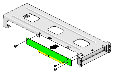
Remove three screws as shown in Figure 2-6.
Separate the riser card from the link bar.
Follow these steps to install the riser card onto the link bar:
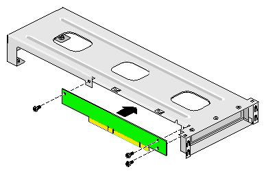
Place the riser card on the link bar as shown in Figure 2-7.
Tighten three screws to secure the riser card to the link bar.
Follow these steps to install an expansion board:
| Note: The SGI 1100 server system supports only 3.3V or universal PCI cards. 5V PCI cards are not supported. |
Remove the chassis cover as described in “Removing the Chassis Cover”.
Remove the link bar as described in “Removing the Link Bar”.
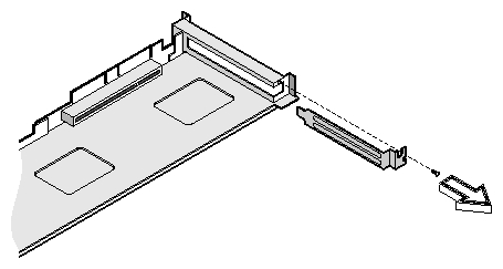
Remove the expansion slot filler plate as shown in Figure 2-8. Save the screw for later use.
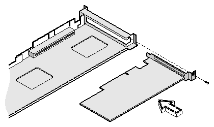
Insert the expansion card into the riser card PCI slot by pushing the expansion board until it is properly seated. Then secure the expansion board to the metal bracket with a screw, as shown in Figure 2-9.
Install the link bar assembly into its slot as described in “Installing the Link Bar”.
Install the chassis cover as described in “Installing the Chassis Cover”.
This section covers the removal and installation of the chassis fan cage and chassis fans.
Follow these steps to remove the chassis fan cage:
Remove the chassis cover as described in “Removing the Chassis Cover”.
Disconnect the three fan connectors from the system board as shown in Figure 2-10.
Remove two screws and pull the chassis fan cage up, as shown in Figure 2-10.

Follow these steps to install the chassis fan cage:
Place the chassis fan cage into the chassis.
Note: Ensure that no cables are pinched between the chassis fan and the chassis during the installation of the chassis fan cage. Tighten two screws to secure the fan cage to the chassis.
Connect the three fan connectors to the system board connectors CN19, CN20, and CN28, as shown in Figure 2-11.
Install the chassis cover as described in “Installing the Chassis Cover”.
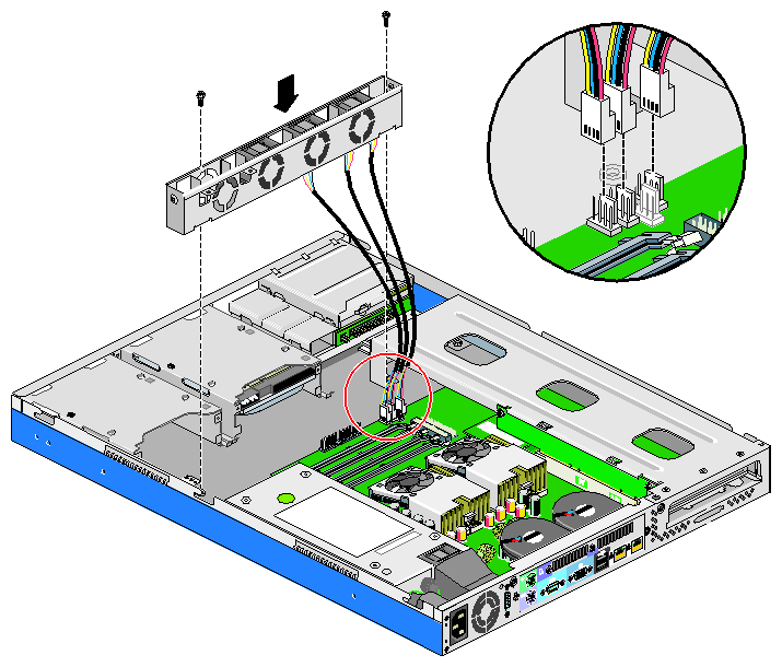
To remove a chassis fan, gently pull up the chassis fan from the fan cage, as shown in Figure 2-12.

To install a chassis fan, insert the chassis fan into the chassis fan cage.
| Note: Ensure that the fan you are installing is properly oriented so as to blow air toward the rear of the chassis. |
This section covers the removal and installation of the rear chassis blowers.
Follow these steps to remove the rear chassis blowers:
Remove the chassis cover as described in “Removing the Chassis Cover”.
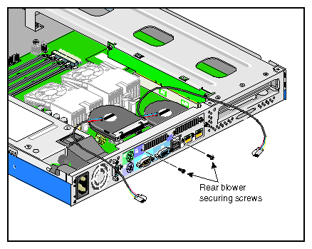
Release two screws to remove the blower as shown in Figure 2-14.
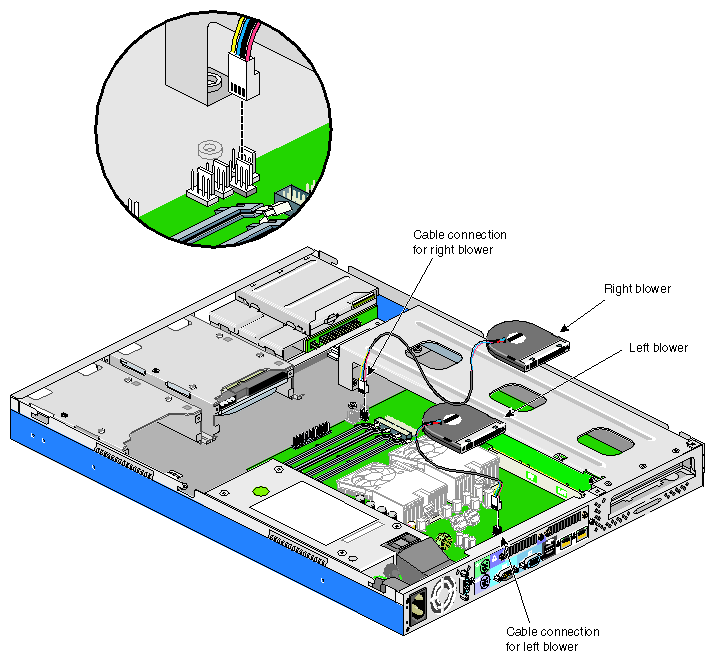
Disconnect the blower cables from the connectors on the system board. See Figure 2-13 for the location of the rear chassis blower cable connectors.
Follow theses steps to install each of the rear chassis blowers:
Place the blower on its opening on the rear panel as shown in Figure 2-14
Connect the rear chassis blower cable to its connector on the system board. The left blower (the one closest to the power supply) plugs into connector CN13 (which is underneath the right blower). The right blower plugs into connector CN23 (which is near the front of the system board). See Figure 2-13 for the locations of the rear chassis blower cable connectors.
Tighten two screws to secure the blower in place.
Install the chassis cover as described in “Installing the Chassis Cover”.
This section covers the removal and installation of the cable modules.
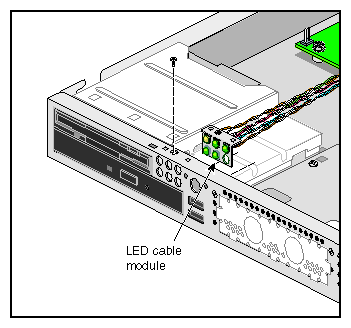
Follow these steps to remove the LED cable module:
Remove the chassis cover as described in “Removing the Chassis Cover”.
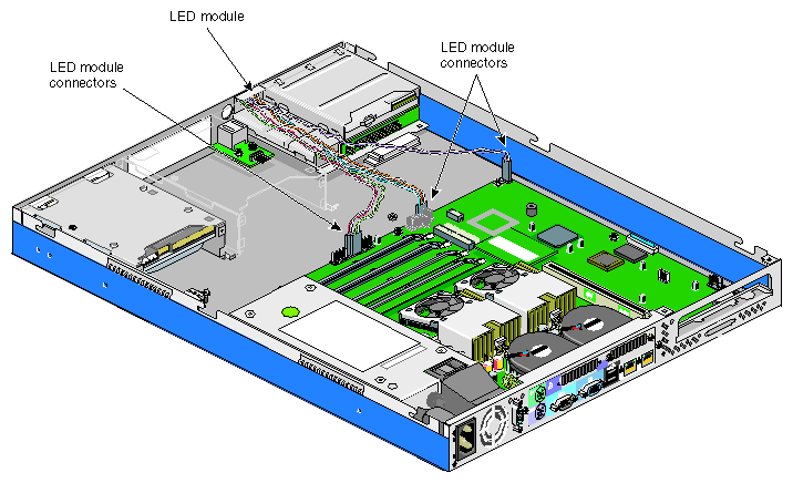
Disconnect all the LED cable connectors from the system board. See Figure 2-15 for the location of the LED cable connectors.
Remove one screw from the LED cable module as shown in Figure 2-16.
Remove the LED cable module from the system.
Follow these steps to install the LED cable module:
Set the LED cable module in place and secure it with one screw as shown in Figure 2-16.
Connect all the LED cable connectors to the system board. See Figure 2-15 for the location of the LED cable connectors.
Install the chassis cover as described in “Installing the Chassis Cover”.
Follow these steps to remove the power switch cable module:
Remove the chassis cover as described in “Removing the Chassis Cover”.
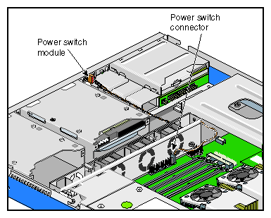
Disconnect the power switch cable connector from the system board. See Figure 2-17 for the location of the power switch cable connector.
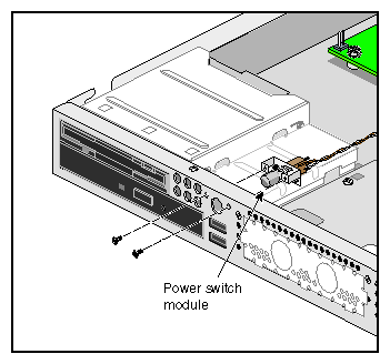
Remove two screws from the power switch cable module as shown in Figure 2-18.
Remove the power switch cable module from the system.

Follow these steps to install the power switch cable module:
Set the power switch cable module in place and secure it with two screws as shown in Figure 2-19.
Connect the power switch cable connector to the system board connector CN15, pins 1 and 2. See Figure 2-17 for the location of the power switch cable connector.
Install the chassis cover as described in “Installing the Chassis Cover”.
Follow these steps to remove the USB daughterboard cable module:
Remove the chassis cover as described in “Removing the Chassis Cover”.
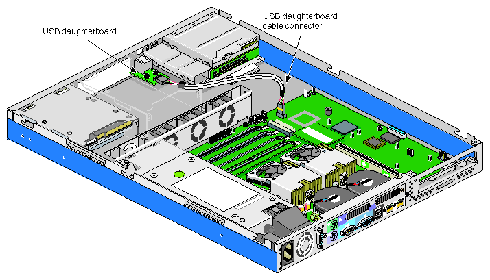
Disconnect the USB daughterboard cable connector from the system board. See Figure 2-20 for the location of the USB daughterboard cable connector.
Remove two screws from the USB daughterboard cable module as shown in Figure 2-21.
Remove the USB daughterboard cable module from the system.
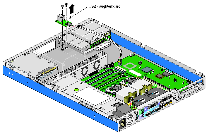
Follow these steps to install the USB daughterboard cable module:
Set the USB daughterboard cable module in place and secure it with two screws as shown in Figure 2-22.
Connect the USB daughterboard cable connector to the system board connector CN30. See Figure 2-20 for the location of the USB daughterboard cable connector.
Install the chassis cover as described in “Installing the Chassis Cover”.

Follow these steps to remove the intrusion alert microswitch cable module:
Remove the chassis cover as described in “Removing the Chassis Cover”.
Disconnect the intrusion alert microswitch cable connector from the system board. See Figure 2-23 for the location of the intrusion alert microswitch cable connector.
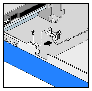
Remove the screw from the intrusion alert microswitch cable module as shown in Figure 2-24.
Remove the intrusion alert microswitch cable module from the system as shown in Figure 2-24.
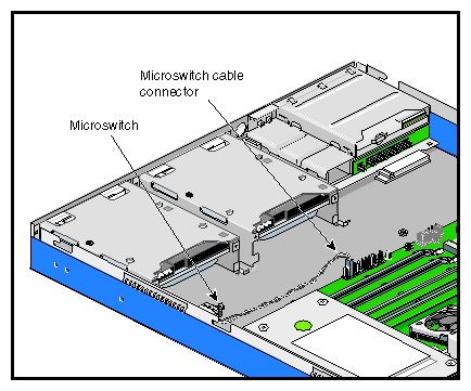

Follow these steps to install the intrusion alert microswitch cable module:
Set the intrusion alert microswitch cable module in place and secure it with one screw as shown in Figure 2-25.
Connect the intrusion alert microswitch cable connector to the system board connector CN15, pins 19 and 20. See Figure 2-23 for the location of intrusion alert microswitch cable connector.
Install the chassis cover as described in “Installing the Chassis Cover”.
This section covers the removal and installation of the removable-media devices.
Follow these steps to remove the diskette drive/CD-ROM drive module:
Remove the chassis cover as described in “Removing the Chassis Cover”.
Remove the link bar, as described in “Removing the Link Bar”.
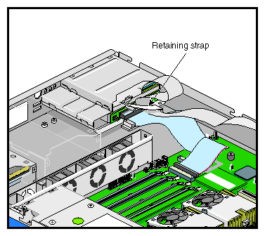
Release the signal cable retaining strap, as shown in Figure 2-26.
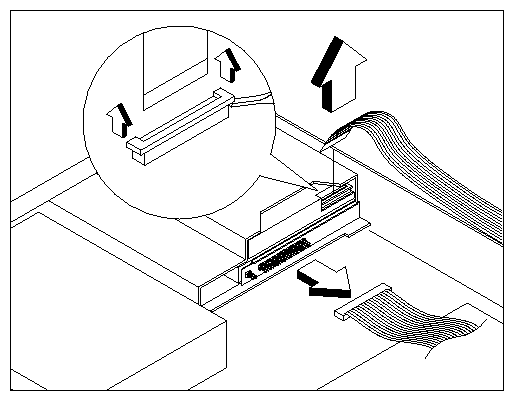
Disconnect the CD-ROM drive signal cable from the CD-ROM drive connector as shown in Figure 2-27.
Note: The CD-ROM drive signal cable is not a standard IDE cable. Instead, the CD-ROM drive uses a signal cable with 50 conductors, some of which supply power. Disconnect the diskette drive signal cable from the diskette drive connector. To do so, lift the connector retaining latch and then pull the signal cable out of the connector as shown in Figure 2-27.
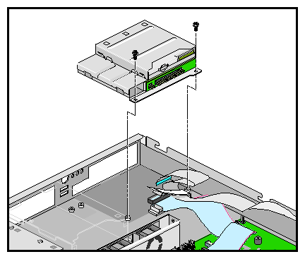
Note: If you need to replace the diskette drive signal cable, follow the same procedure to remove the diskette drive signal cable from the connector on the system board. Note: The diskette drive signal cable is not a standard floppy drive cable. Instead, the diskette drive uses a signal cable with 26 conductors, some of which supply power. Remove two screws that hold the drive module to the chassis as shown in Figure 2-28.
Gently slide the drive module back, and then lift it out of the chassis as shown in Figure 2-28.
Follow these steps to install the diskette drive/CD-ROM drive module:
Insert the drive module into its chassis.
Tighten the two screws to secure the drive module to the chassis as shown in Figure 2-29.
Connect the CD-ROM drive signal cable to the CD-ROM drive connector as shown in Figure 2-29.
Note: The CD-ROM drive signal cable is not a standard IDE cable. Instead, the CD-ROM drive uses a signal cable with 50 conductors, some of which supply power. Connect the diskette drive signal cable to the diskette drive connector. To do so, follow these steps:
Lift the connector retaining latch.
Carefully insert the signal cable into the diskette drive connector.
Push the retaining latch in on both sides of the connector, using a small flat-head screwdriver. See Figure 2-29 for an illustration of the procedure.
Note: Follow the same procedure to connect the diskette drive signal cable to the connector on the system board. Note: The diskette drive signal cable is not a standard floppy drive cable. Instead, the diskette drive uses a signal cable with 26 conductors, some of which supply power.
Secure the signal cable retaining strap.
Install the link bar, as described in “Installing the Link Bar”.
Install the chassis cover as described in “Installing the Chassis Cover”.

Follow these steps to remove the diskette drive:
Remove the diskette drive module as described in “Removing the Diskette Drive/CD-ROM Drive Module”.
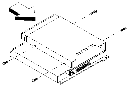
Remove four screws, two on each side of the disk drive module, as shown in Figure 2-30.
Gently pull the drive out of the drive module as shown in Figure 2-30.

Follow these steps to install the diskette drive:
Slide the diskette drive into the drive module as shown in Figure 2-31.
Tighten four screws, two on each side of the disk drive module, as shown in Figure 2-31.
Install the diskette drive module as described in “Installing the Diskette Drive/CD-ROM Drive Module”.
Follow these steps to remove the CD-ROM drive:
Remove the diskette drive module as described in “Removing the Diskette Drive/CD-ROM Drive Module”.
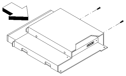
Remove two screws to detach the IDE converter board and the plastic plate as shown in Figure 2-32.
Remove four screws, two on each side of the drive module, as shown in Figure 2-33.
Gently pull the drive out of the drive module as shown in Figure 2-33.


Follow these steps to install the CD-ROM drive:
Remove the drive module from the chassis as described in “Removing the Diskette Drive/CD-ROM Drive Module”.
Insert the CD-ROM drive into the drive module as shown in Figure 2-34.
Tighten the two screws located on the side of the drive module that is in contact with the side of the chassis, as shown in Figure 2-34.
Follow these steps to tighten the two screws on the other side of the drive module:
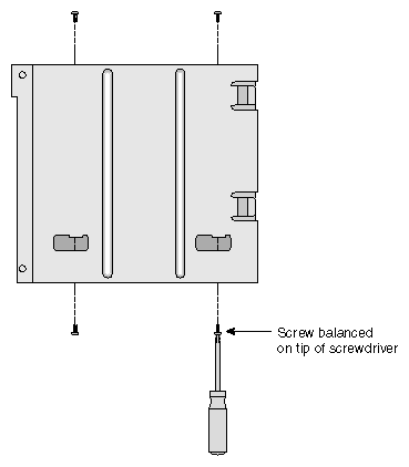
Hold the drive module vertically with the two empty screw holes pointing down as shown in Figure 2-35.
Place a screw on the tip of a small Phillips screwdriver as shown in Figure 2-35.
Note: If the type of Phillips screwdriver you are using does not allow a screw to stay balanced on the tip of the screwdriver, see step 5 for an alternative procedure. Pass the screw through the drive module opening and tighten the screw.
Repeat this procedure for the other screw.
If the type of Phillips screwdriver you are using does not allow you to perform the procedure shown in step 4, follow these alternative steps:
Using needle-nose pliers, hold one of the screws through the hole in the drive module.
With your other hand, tighten the screw with a small Phillips screwdriver.
Repeat this procedure for the other screw.
Install the diskette drive module as described in “Installing the Diskette Drive/CD-ROM Drive Module”.
Install the chassis cover as described in “Installing the Chassis Cover”.
This section covers the removal and installation of a hard drive.
| Note: It is recommended that two people be available for some of the hard drive replacement steps. |
Follow these steps to remove a hard drive:
Remove the chassis cover and the front panel as described in “Opening the Chassis”.
Remove the EMI filler panel from in front of the hard drive by pulling it straight away from the chassis.
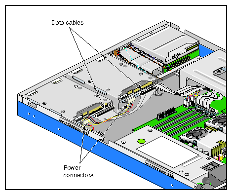
Disconnect the power cable and the data cable from the back of the hard drive as shown in Figure 2-36.
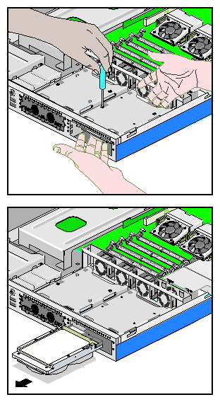
Remove two of the four screws that attach the hard drive to the chassis as shown in Figure 2-37. The first two screws that you remove should be diagonally-located.
While another person holds the hard drive in place, remove the remaining two screws, as shown in Figure 2-38.
Note: If the drive is not held in place when the last 2 screws are removed, it will fall. In order to avoid damage to the hard drive, and if there is no other person available to help with this task, place a soft object under the drive to absorb the shock. Pull the drive out of the chassis.
Insert the EMI filler panel into the chassis if no other drive is to be installed.
Note: Ensure that the arrow on the EMI filler panel points up. Install the chassis cover as described in “Installing the Chassis Cover”.

Follow these steps to install a hard drive:
Remove the chassis cover and the front panel as described in “Opening the Chassis”.
Remove the EMI filler panel by pulling it away from the chassis.
Ensure that the master/slave jumper on the hard drive is set correctly.
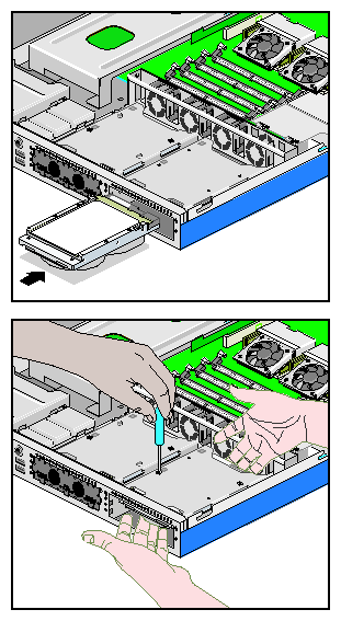
Place the hard drive (with the screw holes and connectors facing up) in the chassis.
While another person holds the hard drive up against the frame, tighten two diagonally-located screws to secure the drive in place, as shown in Figure 2-39.
Note: If there is no other person available to help with this task, place an object under the hard drive to allow you to tighten the first two screws. Tighten the remaining two screws.
Connect the power cable and the data cable to the back of the hard drive.
Insert the EMI filler panel into the chassis.
Note: Ensure that the arrow on the EMI filler panel points up. Install the chassis cover as described in “Installing the Chassis Cover” and the front panel as described in “Removing and Installing the Front Panel”.
This section covers the removal and installation of the power supply module:
Follow these steps to remove the power supply module:
Remove the chassis cover as described in “Removing the Chassis Cover”.
Remove the intrusion alert microswitch module as described in “Replacing the Intrusion Alert Microswitch Cable Module”.
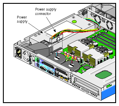
Disconnect the power supply cable from the system board. See Figure 2-40 for the location of the system board power supply connector.
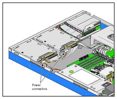
Disconnect the power supply cable from the hard drives. See Figure 2-41 for the location of the hard drive power supply connectors.
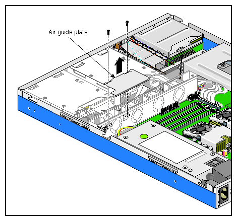
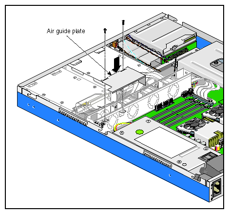
Remove the metal air guide plate by releasing the two screws as shown in Figure 2-42.
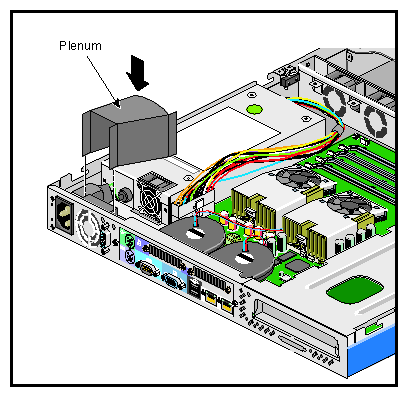
Remove the plastic plenum by separating it from the power supply module and gently detaching it from the power socket module, as shown in Figure 2-43.
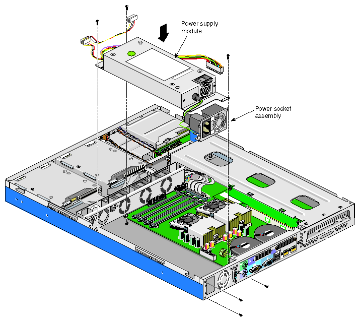
Note: The plastic plenum adheres to the sides of the power socket module. Proceed with care to free the plenum from the power socket module. Remove the three screws from the power supply module as shown in Figure 2-44.
Remove three screws to release the power socket module as shown in Figure 2-44.
Lift up the power supply module from the chassis as shown in Figure 2-44.


Follow these steps to install the power supply module:
Place the power supply module in the chassis as shown in Figure 2-45.
Tighten three screws to attach the power supply socket module to the rear panel as shown in Figure 2-45.
Follow these steps to install the plastic plenum:
Align the narrow part of the plastic plenum with the air vent on the power supply socket module, using the adhesive sides of the plenum to stick it into position, as shown in Figure 2-46.
Align the wide part of the plenum with the power supply fan opening.
Tighten three screws to secure the power supply module to the chassis as shown in Figure 2-45.
Install the metal air guide plate and secure it with two screws as shown in Figure 2-47.
Note: Ensure that all cables fit within the metal air guide plate opening, so that no cables are stuck between the air guide plate and the chassis. Connect the power supply cable to the system board. See Figure 2-40 for the location of the system board power supply connector.
Connect the power supply cable to the hard drives. See Figure 2-41 for the location of the hard drive power supply connectors.
Install the intrusion alert microswitch module as described in “Replacing the Intrusion Alert Microswitch Cable Module”.
Install the chassis cover as described in “Installing the Chassis Cover”.
Follow these steps to remove a processor:
Remove the chassis cover as described in “Removing the Chassis Cover”.
Disconnect the fan/heatsink cables from the system board.
Follow these steps to remove the fan/heatsink assembly from the processor:
Disconnect the fan/heatsink cable from the system board. See Figure 2-50 for the location of the cable connection.
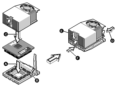
Push on the releasing tab to unhook the metal bracket that is facing the rear of the system. See steps A and B in Figure 2-48.
Lift the fan/heatsink assembly and unhook the other metal bracket. See step C in Figure 2-48.
Remove the fan/heatsink assembly from the processor.
Note: Avoid touching the thermal conductive grease on the bottom of the fan/heatsink and the top of the processor.
Pull up the socket lever (see step D in Figure 2-48). The processor pins will be automatically released from the socket holes.
Lift the processor from the socket as shown in Figure 2-48.
Caution: Do not touch the pins on the processor, so as to ensure long-term reliable contact. If you will now be using the system as a single-CPU system, this processor must be replaced with a terminator board. See “Installing a Processor Terminator Board”.
Install the chassis cover as described in “Installing the Chassis Cover”.

Follow these steps to install a processor:
 | Warning: Both CPUs must be the same speed and cache size. Do not install CPUs with different speeds or cache sizes; this would cause your system to malfunction. |
Remove the chassis cover as described in “Removing the Chassis Cover”.
Pull up the socket lever.
Remove the terminator board, if present.
Insert the processor, making sure that pin 1 (indicated by a triangle at the corner of the processor) connects to hole 1 of the socket, as shown in Figure 2-49.
Caution: Do not touch the pins on the processor, so as to ensure long-term reliable contact. Pull down the socket lever to lock the processor into the socket. See step B in Figure 2-49.
Follow these procedures to attach the heatsink/fan assembly to the processor:
Note: Avoid touching the thermal conductive grease on the bottom of the fan/heatsink and the top of the processor. Spread a small amount of thermal conductive grease on the top center of the processor.
Tilt the heatsink/fan assembly on the processor so as to be able to hook the metal bracket that is facing the front of the chassis over the retaining hook on the CPU socket. See step D in Figure 2-49.
Place the heatsink/fan assembly flat on the processor.
Push the releasing tab to latch the other metal bracket over the retaining hook on the CPU socket. See steps E and F in Figure 2-49.
Plug the fan/heatsink cables to the system board. See Figure 2-50 for the location of the fan/heatsink cable connectors.
Install the chassis cover as described in “Installing the Chassis Cover”.

If you plan to use the SGI 1100 server with only one processor, that one processor must be installed in the processor socket closer to the power supply. Additionally, the processor socket farther from the power supply must contain a processor terminator board.
Follow these steps to install a processor terminator board in an empty processor socket:
Pull up the socket lever.
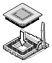
Insert the processor terminator board, making sure that pin 1 (indicated by a triangle at the corner of the processor terminator board) connects to hole 1 of the socket, as shown in Figure 2-51.
Caution: Do not touch the pins on the processor terminator board, so as to ensure long-term reliable contact. Pull down the socket lever to lock the processor terminator board into the socket.
Follow these steps to remove a DIMM:
Remove the chassis cover as described in “Removing the Chassis Cover”.
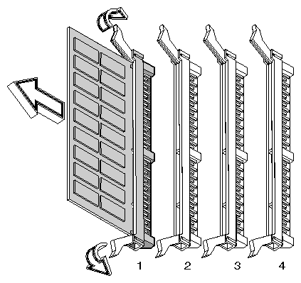
Press the retaining clips on both sides of the socket outward to release the DIMM, as shown in Figure 2-52.
Note: To gently disengage the DIMM from the socket, place your fingers on the top of the DIMM before you press the retaining clips. Caution: The DIMM closest to the processors (DIMM 1) may touch the processor fan cages during the removal of the DIMM. Proceed carefully, do not apply excessive lateral pressure on the DIMM socket. Install the chassis cover as described in “Installing the Chassis Cover”.
The four 168-pin DIMM sockets in the SGI 1100 server support SDRAM-type DIMMs. You may install 128-MB or 512-MB (single density) DIMMs for a maximum of 2 GB of system memory. (the system will also support 1-GB DIMMs, when available, for a maximum of 4 GB of system memory).
| Caution: Only 3.3-volt PC-133 SDRAM DIMMs should be used. The SGI 1100 server system does not support 5-volt memory devices, nor does it support PC-100 or PC-66 SDRAM DIMMs. For a list of qualified vendors, contact your reseller. |
Each of the DIMM sockets is independent from the others. This independence allows you to install DIMMs with different capacities to form different configurations.
Follow these steps to install a DIMM:
Remove the chassis cover as described in “Removing the Chassis Cover”.
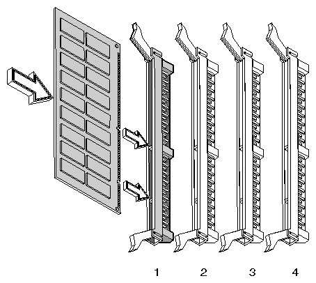
Align the DIMM in an empty slot and press it in until the retaining clips secure the DIMM in place, as shown in Figure 2-53.
Caution: The DIMM closest to the processors (DIMM 1) may touch the processor fan cages during the installation of the DIMM. Proceed carefully, do not apply excessive lateral pressure on the DIMM socket. Note: The DIMM socket is slotted to ensure proper installation. If you slip in a DIMM but it does not completely fit, you may have inserted it the wrong way. Reverse the orientation of the DIMM. Install the chassis cover as described in “Installing the Chassis Cover”.
Follow these steps to replace the CMOS battery:
Remove the chassis cover as described in “Removing the Chassis Cover”.
Push on the retaining clip and remove the old battery from its holder, as shown in Figure 2-54.
Push the new battery into its holder until the retaining clip snaps into place.
Install the chassis cover as described in “Installing the Chassis Cover”.
Note: The system uses a standard CR2032 3V lithium coin-cell battery.

Follow these steps to remove the system board:
Remove the chassis cover as described in “Removing the Chassis Cover”.
Remove the link bar, as described in “Removing the Link Bar”.
Remove the two rear system blowers as described in “Replacing the Rear Chassis Blowers”.
Disconnect all cables from the system board.
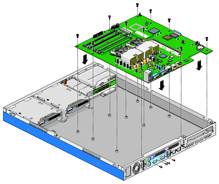
Note: The diskette drive signal cable is delicate. To disconnect the diskette drive signal cable from the diskette drive connector, lift the connector retaining latch and then pull the signal cable out of the connector as shown in Figure 2-27. Remove 12 screws from the system board, 2 jackscrews from serial port 1, and 2 jackscrews from the VGA port, as shown in Figure 2-55.
Gently lift out the system board.

Follow these steps to install the system board:
Place the system board into the chassis so as to align the I/O ports with their corresponding holes on the rear panel.
Tighten 12 screws on the system board, 2 jackscrews on serial port 1, and 2 jackscrews on the VGA port, as shown in Figure 2-56.
Connect all cables to the system board. See “Jumper and Connector Information” in Appendix A for the location of all connectors.
Note: The diskette drive signal cable is delicate. To connect the diskette drive signal cable to the diskette drive connector, follow the steps shown in “Installing the Diskette Drive/CD-ROM Drive Module” Install the two rear system blowers as described in “Installing a Rear System Blower”.
Install the link bar, as described in “Installing the Link Bar”.
Install the chassis cover as described in “Installing the Chassis Cover”.