The SGI 1100 server is a 1U, high-density, rackmountable, PCI bus-based dual-processor system built on an extended ATX baseboard. It comes with two socket 370 processor sockets utilizing one or two Intel Pentium III processors integrated with the Server Works LE north and OSB4 south bridge chipsets. The system board integrates two Intel 82559 10/100 Mbps PCI Ethernet chipsets that supports WOL (wake on LAN) for better remote site management.
For expandability, the system includes one 64-bit/66-MHz PCI bus slot and four DIMM slots that allow memory installation to a maximum of 2 GB using four 512-MB SDRAM (synchronous DRAM) DIMMs.
For connectivity, the system supports four USB (Universal Serial Bus) connectors, a video port, two LAN ports, and other standard features such as two serial ports, a diskette drive interface, and two embedded IDE hard disk interfaces.
The system is fully compatible with Redhat Linux 6.2, Windows NT 4.0, and Windows 2000 Advanced Server OS.
This chapter contains a detailed description of the SGI 1100 server system components.
The Pentium III processor implements Dynamic Execution performance, a multi-transaction system bus, and Intel MMX media enhancement technology. Also, it offers Streaming SIMD (Single Instruction Multiple Data) extensions, which are 70 new instructions enabling advanced imaging, 3D, streaming audio and video, and speech recognition applications. The Pentium III processor delivers higher performance than the previous Pentium processor while maintaining binary compatibility with all previous Intel Architecture processors.
This system board supports 133-MHz GTL+ host bus frequencies for Pentium III processors running at 800 MHz and above.
The four DIMM sockets on board allow memory upgrade to a maximum of 2 GB using four 512-MB SDRAM (Synchronous DRAM) DIMMs. (The DIMM sockets also allow 1024 MB for a maximum upgrade of 4 GB in future models.) For data integrity, the default setting of the ECC (error-correcting code) function of the memory system in BIOS is enabled.
 | Note: Only 3.3-volt SDRAM DIMMs should be used. 5-volt memory devices are not supported. |
The system board supports 133-MHz registered SDRAM; 66-MHz SDRAM is not supported.
The Server Works LE north chipset incorporated as a north bridge is in charge of the host bus interfacing and memory bus control. The memory bus control supports PC-133 SDRAM registered ECC DIMMs up to a total of 4 GB. The north bridge provides one 64-bit PCI bus running at 66 MHz.
The south bridge subset provides the legacy ISA interface, USB port, ATA33, and System Management Bus (SMB). The BMC (Baseboard Management Control) was embedded on the motherboard and connected with the south bridge to provide the ASM and RDM functions and industry standard IPMI protocol.
Another cost-effective feature for network solution is the integration of Intel's 82559 10/100 Mbps Fast Ethernet controller which supports Advanced Configuration and Power Interface (ACPI) 1.20A-based power management, wake on Magic Packet, wake on interesting packet, advanced SMB-based manageability, Wired for Management (WfM) 2.0 compliance, IP checksum assist, PCI 2.2 compliance, and PC 98 and PC 99 compliance.
The ATI Rage XL harbors 2D and 3D display capabilities that bring life to any multimedia and work applications. It also supports hardware DVD decoding. With remarkable color depths and high resolutions of up to 1600x1200, it enhances every visual experience on your system.
The on-board ATI Rage XL chipset comes with 4 MB of video memory.
Figure 1-1 shows a block diagram of the SGI 1100 system board components.

This section describes the front controls and indicators of the SGI 1100 server, as shown in Figure 1-2.

Table 1-1 describes the front controls and indicators that are indicated in Figure 1-2.
Table 1-1. Front Controls and Indicators
No. | Item |
|---|---|
1 | Slim-type floppy disk drive LED |
2 | Slim-type floppy disk drive |
3 | Slim-type floppy disk drive eject button |
4 | Event LED |
5 | Hard disk drive access LED |
6 | Power LED |
7 | LAN 2 access LED |
8 | LAN 1 access LED |
9 | Power button |
10 | Metal handle |
11 | USB ports (2 ports) |
12 | Slim-type CD-ROM drive emergency eject hole |
13 | Slim-type CD-ROM drive eject button |
14 | Slim-type CD-ROM drive LED |
The general event LED indicates the following occurrences:
Temperature, voltage, system fan, or fuse events.
CPU IERR and Thermtrip error.
System fan or power supply unplug.
Removal of top cover.
Uncorrectable memory error (multiple ECC errors).
PCI PERR or SERR error.
If all of the preceding events recover, the Baseboard Management Controller (BMC) should turn off the LED.
| Note: The BMC will not turn on the general event LED for BIOS POST, PCI hot plug, and correctable memory error events. |
This section describes the rear panel I/O ports and other features, as shown in Figure 1-3.
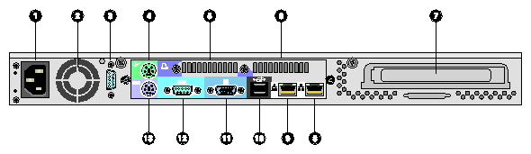
Table 1-2 describes the rear panel I/O ports and features that are indicated in Figure 1-3.
Table 1-2. Rear Panel I/O Ports and Features
No. | Item |
|---|---|
1 | AC power input |
2 | Ventilation |
3 | Serial port 2 |
4 | PS/2 mouse port |
5 | Ventilation |
6 | Ventilation |
7 | Add-on card bracket |
8 | LAN 2 port (RJ-45) |
9 | LAN 1 port (RJ-45) |
10 | USB ports (2 ports) |
11 | VGA port |
12 | Serial port 1 |
13 | PS/2 keyboard port |
This section describes the location of the main components inside the SGI 1100 server, as shown in Figure 1-4.

Table 1-3 describes the internal components that are indicated in Figure 1-4.
Table 1-3. Internal Components
No. | Item |
|---|---|
1 | IDE hard disk drive bay |
2 | IDE hard disk drive bay |
3 | Slim-type CD-ROM drive |
4 | Slim-type floppy disk drive |
5 | CPUs and fan/heatsinks |
6 | System board |
7 | PCI expansion card slot and link bar |
8 | Rear blowers |
9 | Power supply |
10 | Housing fans |
The system supports the power-management function that conforms to the power-saving standards of the U.S. Environmental Protection Agency (EPA) Energy Star program. It also offers Plug-and-Play, which helps users avoid configuration problems and thus makes the system more user-friendly.
Table 1-4 lists the power-saving modes and their respective characteristics. These power management features are only available if the operating system running on the system supports them
Table 1-4. Power-Saving Mode Characteristics List
Power-saving mode | Characteristics |
|---|---|
Device standby mode | Independent power management timer for HDD devices (0-15 minutes, time step = 1 minute) Hard disk drive goes into STANDBY mode (for ATA standard interface) Disable V-sync to control the VESA DPMS monitor Resume method: device activated (keyboard for DOS, keyboard and mouse for Windows) Resume recovery time: 3-5 seconds |
Global standby mode | Global power management timer (1-60 minutes) Hard disk drive goes into STANDBY mode (for ATA standard interface) Disable H-sync and V-sync signals to control the VESA DPMS monitor Resume recovery time: 7-10 seconds |
System suspend mode | Independent power management timer (1-60 minutes) or pushing external switch button CPU goes into SMM (system management mode) CPU asserts STPCLK# and goes into the stop grant state LED on the panel flashes in amber color Hard disk drive goes into SLEEP mode (for ATA standard interface) Disable H-sync and V-sync signals to control the VESA DPMS monitor Return to original state by pushing external switch button. |
IPMI is an open standard hardware manageability interface specification. It provides an architecture that defines how unique devices can all communicate with the CPU in a standard way.
With IPMI, the CPU only communicates one event to the IPMI event log. The CPU only “asks” what has changed since the last time it asked. Every device communicates directly, through IPMI, to the event log, which is used to record, in a consistent way, all status events for the unique device. This simplifies the agent-handling routine. The system only needs a single agent, and it does not need to be changed when you change from five devices to manage, for example, to six. And the system does not need to change the way the CPU checks the event log when a new device is added to the system; it always checks in the same way, whether there is one device or 100 devices. With IPMI, use of the CPU is minimized, so overall system performance improves.
The following are the four elements of IPMI, each of which is described in the sections that follow:
Intelligent Platform Management Interface
Intelligent Platform Management Bus
Intelligent Chassis Management Bus
Baseboard Management Controller
IPMI is the specification for the management controller command sets, including command sets for sensors, event logs, and sensor data record access. It is also the specification for the data formats, including sensor data records, event log entries, and FRU inventory information. IPMI is also the name used for the overall standardization effort.
IPMB is the I2C-based, multi-master bus used for intra-chassis communication with “satellite” management controllers. Here sensor devices and cards with IPMI bus access can be added to the IPMI standard.
The system has the following major components:
Processor
Supports dual Pentium III processors installed in a socket 370 running a 133-MHz Front Side Bus (FSB).Chipset
ServerWorks ServerSet III LE chipset consists of CNB30LE (Champ North Bridge) and OSB4 (Open South Bridge) is in charge of the host interfacing, memory system control, PCI interfacing, and data steering.LAN controller
Two on-board Intel 82559 10/100-Mb/s PCI LAN controllers.Memory
The CNB30LE champ north bridge consists of a system memory controller integrated with four DIMM sockets that support 128-, 512- and 1024-MB (in the future) registered ECC SDRAM DIMMs with a maximum memory upgrade of 4 GB (1024 MB x 4 DIMM modules).Cache
256-KB second-level write-back PipeLined-Burst SRAM supported cache on Pentium III processor.Video
On board PCI VGA controller (ATI Rage XL) with 4-MB SDRAM graphics memory support.BIOS
512-KB Flash ROM built-in 28SF040A-90 for system and IPMI BIOS.
Y2K NSTL-compliant.
Real-time clock (RTC)
256-byte battery-backed CMOS RAM.
Built-in SMC FDC37B787 super I/O controller.
System clock/calendar with battery backup.
Power supply
Standard 200W power supply.Memory interface
Four DIMM sockets support four PC 133 registered ECC SDRAM modules.IDE interface
E-IDE controller built-in RCC OSB4 (Open South Bridge).
PCI bus master dual-channel E-IDE interface.
Provides up to four IDE devices.
Supports PIO mode 4 transfers up to 16.7 MB/sec, DMA mode 2, and Ultra DMA33 (33 MB/sec) mode.
Diskette drive interface
Compatible with IBM PC AT disk drive system.
16-byte data FIFO.
Data rate and drive control register.
DMA enable logic.
480 addresses, up to eight IRQs, and seven DMA Options.
Supports 3.5-inch diskette drives.
Supports 360K-, 720K-, 1.2M-, 1.44M-, 2.88M-byte format, and 250K-, 300K-, 500K-, 1M-, or 2M-bps data transfer rate.
Supports 3-mode diskette drive.
PCI Slots
One 64-bit/66-MHz PCI 2.2-compliant PCI slot with a PCI riser card.BMC interface
Two 24-pin BMC (Baseboard Management Controller) interfaces.I/O APIC device for SMP interrupt support.
Server management controller chipset.
Serial port
Two high-speed NS16C550-compatible UART with send/receive 16-byte FIFO serial ports.USB port
Four USB ports support Universal HCI specification for USB 1.0.PS/2 keyboard and mouse port
One external monitor port
LAN connector
Two RJ-45 jacks for 10BaseT or 100BaseTX LAN connectors.