This chapter describes the Power-on Self Test (POST) and system configuration utilities. Table 3-1 briefly describes the utilities.
Table 3-1. Configuration Utilities
Use the keyboard's numeric pad to enter numbers and symbols.
Each time you turn on the system, the power-on self test (POST) starts running. POST checks the baseboard and its processors, memory, keyboard, and most installed peripheral devices. During the memory test, POST displays the amount of memory it is able to access and test. The length of time needed to test memory depends on the amount of memory installed. POST is stored in flash memory. POST runs in a manner similar to the following:
Turn on your video monitor and system. After a few seconds, POST begins to run.
After the memory test, these screen prompts and messages appear:
Keyboard Detected
Mouse Initialized
Press <F2> to enter Setup
Operating System not found |
If you do not press F2, the boot process continues and various messages appear. The message content may differ based on your system configuration and operating system. User's with NT systems may see a message similar to the following:
Press <Ctrl><C> to enter SCSI Utility

Note: The next two steps are applicable to NT users. Press Ctrl+C if SCSI devices are installed. When the utility opens, follow the displayed instructions to configure the onboard SCSI host adapter settings and to run the SCSI utilities. If you do not enter the SCSI utility, the boot process continues.
Press Esc during POST to access a boot menu when POST finishes. From this menu, you can choose the boot device or enter BIOS Setup.
After POST completes, the system beeps once.
What appears on the screen after this depends on if you have an OS loaded and if so, which one.
If the system halts before POST completes running, it emits a beep code indicating a critical system error that requires immediate attention. If POST can display a message on the video display screen, the speaker beeps twice as the message appears.
Note the screen display and write down the beep code you hear; this information is useful for your service representative.
This section describes the BIOS Setup options. Use Setup to change the system configuration defaults. You can run Setup with or without an OS being present. Setup stores most of the configuration values in battery-backed CMOS; the rest of the values are stored in flash memory. The values take effect when you boot the system. POST uses these values to configure the hardware; if the values and the actual hardware do not agree, POST generates an error message. You must then run Setup to specify the correct configuration.
You can run Setup to modify any standard PC baseboard feature such as:
Select diskette drive
Select parallel port
Select serial port
Set time/date (to be stored in RTC)
Configure IDE hard drive
Specify boot device sequence
Enable SCSI BIOS
You must run the SSU instead of Setup to do the following:
Enter or change information about a board
Alter system resources (for example, interrupts, memory addresses, I/O assignments) to user–selected choices instead of choices selected by the BIOS resource manager
If the default values ever need to be restored (after a CMOS clear, for example), you must run Setup again. Referring to the worksheets could make your task easier.
If the diskette drive is misconfigured so that you cannot access it to run a utility from a diskette, you might need to clear CMOS memory. You must open the system, change a jumper setting, use Setup to check and set diskette drive options, and change the jumper back. This procedure should be done by a trained service person, see the SGI 1400 Server Family Maintenance and Upgrades Guide.
You can enter and start Setup under several conditions:
When you turn on the system, after POST completes the memory test
When you reboot the system by pressing Ctrl+Alt+Del while at the DOS operating system prompt
When you have moved the CMOS jumper on the baseboard to the “Clear CMOS” position (enabled); see the SGI 1400 Server Family Maintenance and Upgrades Guide.
In the three conditions listed above, after rebooting, you will see this prompt:
Press <F2> to enter SETUP |
In a fourth condition, when CMOS/NVRAM has been corrupted, you will see other prompts but not the F2 prompt:
Warning: cmos checksum invalid Warning: cmos time and date not set |
In this condition, the BIOS will load default values for CMOS and attempt to boot.
Setup has six major menus and several submenus:
Main Menu
Primary IDE Master and Slave
Keyboard Features
Advanced Menu
PCI Configuration
PCI Device, Embedded SCSI
PCI Devices
I/O Device Configuration
Advanced Chipset Control
Security Menu
Server Menu
System Management
Console Redirection
Boot Menu
Boot Device Priority
Hard Drive
Exit Menu
Table 3-3 provides some information on using the menus and submenus.
Table 3-3. Setup Menu Control Information
To: | Press: |
|---|---|
Get general help | F1 or Alt+H |
Move between menus | ← → |
Go to the previous item | Up arrow |
Go to the next Item | Down arrow |
Change the value of an item | + or - |
Select an item or display a submenu | Enter |
Leave a submenu or exit Setup | Esc |
Reset to Setup defaults | F9 |
Save and exit Setup | F10 |
Table 3-4. Restricted Menu Selection and Submenus
When you see this: | What it means: |
|---|---|
On screen, an option is shown but you cannot select it or move to that field. | You cannot change or configure the option in that menu screen. Either the option is autoconfigured or autodetected, or you must use a different Setup screen, or you must use the SSU. |
On screen, the phrase Press Enter appears next to the option. | Press Enter to display a submenu that is either a separate full-screen menu or a pop-up menu with one or more choices. |
The following sections list the features that display onscreen after you press F2 and enter Setup. Not all of the option choices are described:
a few are not user-selectable and are displayed for information only
many of the choices are relatively self-explanatory.
The main menu (see Table 3-5) lists the selections you can make on the main menu itself. Use the submenus for other selections. Default values are in bold.
Table 3-5. Main Menu Features and Descriptions
Feature | Choices | Description |
|---|---|---|
System Time | HH:MM:SS | Sets the system time. |
System Date | MM/DD/YYYY | Sets the system date. |
Legacy Diskette A: | Disabled | Selects the diskette type. |
Legacy Diskette B: | Disabled | Selects the diskette type. |
Hard Disk Pre-delay | Disabled | Adds a delay before the first BIOS access of a hard disk drive. Some hard disk drives hang if accessed before they initialize themselves. This delay ensures the hard disk drive has initialized after power on, before being accessed. |
Primary Master | N/A | Enters submenu. |
Primary Slave | N/A | Enters submenu. |
Keyboard Features | N/A | Enters submenu. |
Language | English (US) | Selects which language BIOS displays. Note: Serial redirection does not work with Kanji. |
In Table 3-6, the features other than “Type” appear only for Type Auto if a drive is detected.
Table 3-6. Primary IDE Master and Slave Submenu
Feature | Choices | Description |
|---|---|---|
Type | Auto | Auto allows the system to attempt autodetection of the drive type. |
Cylinders | 1 to 2048 | Number of Cylinders on Drive. |
Heads | 1 to 16 | Number of read/write heads on drive. |
Sectors | 1 to 64 | Number of sectors per track. |
Maximum Capacity | N/A | Computed size of drive from cylinders, heads, and sectors entered. |
Multi-Sector Transfers | Disabled | Determines the number of sectors per block for multisector
transfers. |
LBA Mode Control | Disabled | Enabling LBA causes logical block addressing to be used in place of
cylinders, heads, and sectors. |
32 Bit I/O | Disabled | Enabling allows 32-bit IDE data transfers. |
Transfer Mode | Standard | Selects the method for moving data to and from the drive. |
Ultra DMA | Disabled | For use with Ultra DMA drives. |
Table 3-7 summarizes the features of the keyboard submenu.
Table 3-7. Keyboard Features Submenu
Feature | Choices | Description |
|---|---|---|
Num Lock | Auto | Selects power-on state for Num Lock. |
Key Click | Disabled | Enables or disables key click. |
Keyboard auto-repeat rate | 30, 26.7, 21.8, 18.5, 13.3, 10, 6, or 2 per second | Selects key repeat rate. |
Keyboard auto-repeat delay | 1/4 sec | Selects delay before key repeat. |
You can make the following selections on the advanced menu itself, see Table 3-8. Use the submenus for the three other selections that appear on the advanced menu.
Table 3-8. Advanced Menu Features
Feature | Choices | Description |
|---|---|---|
Plug and Play OS | No | Select Yes if you are booting a Plug and Play-capable OS. |
Reset Configuration Data | No | Select Yes if you want to clear the system configuration data during next boot. System automatically resets to No in next boot. |
PCI Configuration | N/A | Enters submenu. |
I/O Device Configuration | N/A | Enters submenu. |
Use Multiprocessor Specification | 1.1 | Selects the version of multiprocessor specification to use. Some operating systems require version 1.1 for compatibility reasons. |
Large Disk Access Mode | LBA | Applies to IDE drives only; refers to the method used to
access the drive. |
Pause Before Boot | Enabled | Enables five-second pause before booting OS. |
Advanced Chipset Control | N/A | Enters submenu. |
The PCI Configuration Menu contains selections that access other submenus.
Table 3-9 shows the PCI device options in the embedded SCSI submenu.
Table 3-9. PCI Device, Embedded SCSI Submenu
Feature | Choices | Description |
|---|---|---|
Option ROM Scan | Enabled | Enables option ROM scan of the selected device. |
Enable Master | Disabled | Enables selected device as a PCI bus master. |
Latency Timer | Default | Minimum guaranteed time, in units of PCI bus clocks, that a device can be master on a PCI bus. Typically, option ROM code overwrites the value set by the BIOS. |
Table 3-10 shows the options in the PCI devices submenu.
Table 3-10. PCI Devices Submenu
Feature | Choices | Description |
|---|---|---|
Option ROM Scan | Enabled | Enables option ROM scan of all devices other than the onboard SCSI controllers. |
Enable Master | Enabled | Enables all devices, other than the onboard SCSI controllers, as a PCI bus master. |
Latency Timer | Default | Minimum guaranteed time, in units of PCI bus clocks, that a device can be master on a PCI bus. Typically, option ROM code overwrites the value set by the BIOS. |
Table 3-11 lists the entries in the I/O device configuration submenu.
Table 3-11. I/O Device Configuration Submenu
Feature | Choices | Description |
|---|---|---|
Serial Port A | Disabled |
|
Base I/O Address | 3F8 | Selects the base I/O address for COM port A. |
Interrupt | IRQ 4 | Selects the IRQ for COM port A. |
Serial Port B | Disabled |
|
Mode | Normal | Selects mode for COM port B. |
Base I/O Address | 3F8 | Selects the base I/O address for COM port B. |
Interrupt | IRQ 4 | Selects the interrupt for COM port B. |
Parallel Port | Disabled |
|
Mode | ECP | Selects mode for parallel port. |
Base I/O Address | 378 | Selects the base I/O address for parallel port. |
Interrupt | IRQ 5 | Selects the interrupt for parallel port. |
DMA channel | DMA 1 | Selects the DMA channel for parallel port. |
Floppy disk controller | Disabled | Enables onboard diskette controller. |
Base I/O Address | Primary | Sets the base I/O address for the diskette controller. |
PS/2 Mouse | Auto | Enables or disables onboard mouse. Disabling the mouse frees up IRQ 12. If this feature is enabled, the OS can determine whether to enable or disable the mouse. |
Table 3-12 lists the options in the advanced chipset control submenu.
Table 3-12. Advanced Chipset Control Submenu
Feature | Option | Description |
|---|---|---|
Address Bit Permuting | Disabled | To be enabled, there must be a power of 2 number of rows, all rows must be the same size, and all populated rows must be adjacent and start at row 0. Two-way or four-way permuting is set automatically based on memory configuration. |
Base RAM Step | 1 MB | Tests base memory once per MB, once per KB, or every location. |
Extended RAM Step | 1 MB | Tests extended memory once per MB, once per KB, or every location. |
L2 Cache | Enabled | When enabled, the secondary cache is sized and enabled. For Core Clock Frequency-to-System Bus ratios equal to two, BIOS automatically disables the L2 cache. |
ISA Expansion Aliasing | Enabled | When enabled, every I/O access with an address in the range x100-x3FFh, x500-x7FFh, x900-xBFF, and xD00-xFFFh is internally aliased to the range 0100-03FFh before any other address range checking is performed. |
Memory Scrubbing | Disabled | When enabled, BIOS automatically detects and corrects SBEs. |
Restreaming Buffer | Enabled | When enabled, the data returned and buffered for a Delayed Inbound Read can be reaccessed following a disconnect. |
Read Prefetch for PXB0A | N/A | Information field only. Configures the number of Dwords that are prefetched on Memory Read Multiple commands. |
Read Prefetch for PBX0B | N/A | Information field only. Configures the number of Dwords that are prefetched on Memory Read Multiple commands. |
You can make the following selections on the Security Menu. Enabling the Supervisor Password field requires a password for entering Setup. The passwords are not case sensitive (see Table 3-13).
Feature | Choices | Description |
|---|---|---|
Administrator Password is | Clear | Status only; user cannot modify. Once set, this can be disabled by setting it to a null string or by clearing the password jumper on the baseboard. |
User Password is | Clear | Status only; user cannot modify. Once set, this can be disabled by setting it to a null string or by clearing the password jumper on baseboard. |
Set Administrative Password | Press Enter | When the Enter key is pressed, the user is prompted for a password; press the Esc key to abort. Once set, this can be disabled by setting it to a null string or by clearing the password jumper on the baseboard. |
Set User Password | Press Enter | When the Enter key is pressed, the user is prompted for a password; press Esc key to abort. Once set, this can be disabled by setting it to a null string or by clearing the password jumper on baseboard. |
Password on Boot | Disabled | If enabled and the user password is set, the system prompts the user for a password before the system boots. |
Fixed Disk Boot Sector | Normal | Write-protects boot sector on hard disk to protect against viruses. |
System Backup Reminder | Disabled | Displays system-backup reminder message at boot. |
Virus Check Reminder | Disabled | Displays virus-check reminder message at boot. |
Secure Mode Timer | Disabled | Period of keyboard or PS/2 mouse inactivity specified for secure mode to activate. A password is required for secure mode to function. Cannot be enabled unless at least one password is enabled. |
Secure Mode Hot
Key | [ ] | Key assigned to invoke the secure mode feature. Cannot be enabled unless at least one password is enabled. Can be disabled by entering a new key followed by a backspace or by entering Delete. |
Secure Mode Boot | Disabled | System boots in secure mode. The user must enter a password to unlock the system. Cannot be enabled unless at least one password is enabled. |
Video Blanking | Disabled | Blank video when secure mode is activated. The user must enter a password to unlock the system. Cannot be enabled unless at least one password is enabled. |
Floppy Write Protect | Disabled | When secure mode is activated, the diskette drive is write protected. The user must enter a password to re-enable diskette writes. Cannot be enabled unless at least one password is enabled. |
Table 3-14 and the following subsections describe and list the submenus and features of the server menu.
Table 3-14. Server Menu Options
Feature | Choices | Description |
|---|---|---|
System Management | N/A | Enters submenu. |
Console Redirection | N/A | Enters submenu. |
Processor Retest | No | Instructs BIOS to clear historical processor status and to retest all processors on next boot. |
Table 3-15 describes the choices available in the system management submenu.
Table 3-15. System Management Submenu
Feature | Choices | Description |
|---|---|---|
Server Management Mode | Disabled | Enabled loads Server Management Interrupt handler, which handles system errors. |
System Event Logging | Disabled | Enabled forces BIOS and BMC to log system events. |
Clear Event Log | Disabled | Enabled clears the system event log. |
Assert NMI on AERR | Disabled | Enabled generates a nonmaskable interrupt (NMI) on an address parity error (AERR). |
Assert NMI on BERR | Disabled | Enabled generates an NMI on a bus error (BERR). |
Assert NMI on PERR | Disabled | Enabled generates an NMI on a parity error (PERR). To activate this feature, the system error (SERR) option must be enabled. |
Assert NMI on SERR | Disabled | Enabled generates an NMI on SERR. |
Enabled Host Bus Error | Disabled | Enables host single-bit errors (SBEs) and multiple-bit errors (MBEs). |
Table 3-16 describes the feature choices under the console redirection submenu.
Table 3-16. Console Redirection Submenu
Feature | Choices | Description |
|---|---|---|
COM Port Address | Disabled | When enabled, console redirection uses the I/O port specified. |
IRQ # | None, 3, or 4 | When console redirection is enabled, this displays the IRQ assigned per the address chosen in the COM Port Address field. |
Baud Rate | 9600 | When console redirection is enabled, use the baud rate
specified. |
Flow Control | No flow control | None disallows flow control. |
You can make the following menu and submenu selections on the boot menu itself (see Table 3-17 and the following subsections).
Feature | Choices | Description |
|---|---|---|
Floppy Check | Disabled | If Enabled, system verifies diskette type on boot. |
Multi-boot Support | Disabled | Enable this option only if the total number of hard drives is less than eight. |
Boot Device Priority | N/A | Enters submenu. |
Hard Drive | N/A | Enters submenu. |
Removable Devices | N/A | Enters submenu. |
Maximum Number of I2O Drives | 1 | Selects the maximum number of I2O drives assigned a DOS drive letter. |
Message Timeout Multiplier | 1, 2, 8, 10, 50, 100, 1000 | All timeout values are multiplied by this number. |
Use the up- or down-arrow keys to select a device in the boot device priority submenu. Press the + or - key to move the device higher or lower in the boot priority list, see Table 3-18.
Table 3-18. Boot Device Priority Submenu
Boot Priority | Device | Description |
|---|---|---|
1. | Diskette Drive | Attempts to boot from drive A. |
2. | Removable Devices | Attempts to boot from a removable media device. |
3. | Hard Drive | Attempts to boot from a hard drive device. |
4. | ATAPI CD-ROM Drive | Attempts to boot from an ATAPI CD-ROM drive. |
For options on this menu, use the up or down arrow keys to select a device, see Table 3-19. Press the + or - key to move the device higher or lower in the boot priority list.
Table 3-19. Hard Drive Submenu
Option | Description |
|---|---|
1. Drive #1 (or actual drive string) | N/A |
2. Other bootable cards | Covers all the boot devices that are not reported to the system BIOS through the BIOS boot specification mechanism. |
You can make the following selections on the exit menu, as shown in Table 3-20. Select an option using the up or down arrow keys. Press Enter to run the option. Pressing Esc does not exit the menu, you must select an item from the menu or menu bar to exit.
Choices | Description |
|---|---|
Exit Saving Changes | Exits after writing all modified Setup item values to NVRAM. |
Exit Discarding Changes | Exits leaving NVRAM unmodified and continues POST. User is prompted if any of the Setup fields were modified. |
Load Setup Defaults | Loads default values for all Setup items. |
Load Custom Defaults | Loads settings from custom defaults. |
Save Custom Defaults | Saves present Setup values to custom defaults. These settings
override the standard BIOS defaults; BIOS loads these values
when CMOS is corrupted or when the Clear CMOS jumper is in
the clear position. |
Discard Changes | Reads previous values of all Setup items from NVRAM. |
Save Changes | Writes all Setup item values to NVRAM. |
The SSU is on the configuration software CD shipped with the server. The SSU provides a graphical user interface (GUI) over an extensible framework for server configuration. The SSU framework supports the following functions and capabilities:
Assigns resources to baseboard devices and add-in boards before loading the OS
Lets you specify boot device order and system security options
Permits viewing and clearing of the system event log (SEL)
Permits viewing of the system FRU and SDRs
Allows troubleshooting of the server when the OS is not operational
Provides a system-level view of the server's I/O devices
The SSU is a DOS-based utility that supports extended system configuration operations for onboard resources and add-in boards. Use the SSU when you need to:
Add and remove boards affecting the assignment of resources (ports, memory, IRQs, DMA)
Modify the server's boot device order or security settings
Change the server configuration settings
Save the server configuration
View or clear the SEL
View FRU information
View the SDR table
If you install or remove an ISA add-in board, you must run the SSU to reconfigure the server. Running the SSU is optional for PCI and Plug and Play ISA add–in boards.
The SSU is PCI-aware and complies with the ISA Plug and Play specifications; it works with any compliant configuration (.CFG) files supplied by the peripheral device manufacturer.
The baseboard comes with a .CFG file describing the characteristics of the board and the system resources it requires. The configuration registers on PCI and ISA Plug and Play add-in boards contain the same type of information in a .CFG file. Some ISA boards also come with a .CFG file.
The SSU uses the information provided by .CFG files, configuration registers, flash memory, and the information that you enter, to specify a system configuration. The SSU then writes the configuration information to flash memory.
The SSU stores configuration values in flash memory. These values take effect when you boot the server. POST checks the values against the actual hardware configuration; if the values do not agree, POST generates an error message. You must then run the SSU to specify the correct configuration before the server boots.
The SSU always includes a checksum with the configuration data so the BIOS can detect any potential data corruption before the actual hardware configuration takes place.
You can run the SSU directly from the configuration software CD after you have installed a CD–ROM drive, or from a set of DOS diskettes.
If you choose to run the SSU from DOS diskettes, you must copy the SSU from the CD to the diskettes and follow the instructions in the included README.TXT file to prepare the diskettes.
If your diskette drive is disabled or improperly configured, you must use the flash-resident Setup utility to enable it so you can use the SSU. If necessary, you can disable the drive after exiting the SSU. Information entered using the SSU overrides any entered using Setup.
You can run the SSU either locally or remotely. The following subsections describe these options.
Running the ssu.bat file provided on the SSU media starts the SSU. If the server boots directly from the SSU media, the ssu.bat file runs automatically. If the server boots from different media, the SSU can be started manually or by another application. When the utility starts in the local execution mode (the default mode), the SSU accepts input from the keyboard and/or mouse. The SSU presents a VGA-based GUI on the primary monitor.
The SSU runs from writable, nonwritable, removable, and nonremovable media. If the SSU is run from nonwritable media, user preference settings (like screen colors) cannot be saved.
The SSU supports the ROM-DOS V6.22 OS. It can run on other ROM-DOS compatible OSs, but they are not supported. The SSU will not operate from a “DOS window” running under another OS.
The SSU is a collection of task-oriented modules plugged into a common framework called the Application Framework (AF). The AF provides a launching point for individual tasks and a location for setting customization information.
Start the SSU through one of two ways:
Directly from the Server Configuration Software CD:
Insert the configuration software CD into your server's CD-ROM drive.
Press the reset button or Ctrl+Alt+Del to reboot. When prompted to do so, press F2 to enter BIOS Setup.
From the Boot Menu, select the Boot Device Priority option and press Enter.
Select CD-ROM as your primary boot device by using the + key to move it to the top of the list.
Press Esc to exit the Boot Menu and F10 to save your choice.
The server will boot from the CD-ROM and display a menu of options. Follow the instructions in the menu to start the SSU.
After creating a set of SSU diskettes from the CD:
Insert the first SSU diskette in drive A.
Press the reset button or Ctrl+Alt+Del and press F2 to enter the BIOS Setup and reconfigure your system to reboot the server from the diskette.
Use the same steps as listed above for the CD drive but select the diskette drive.
When the SSU title appears on the screen, select Utilities and press Enter.
Select Run System Setup Utility then press Enter.
The mouse driver loads if it is available; press Enter to continue.
This message appears:
Please wait while the Application Framework loads....
When the main window of the SSU appears, you can customize the user interface (UI) before continuing.
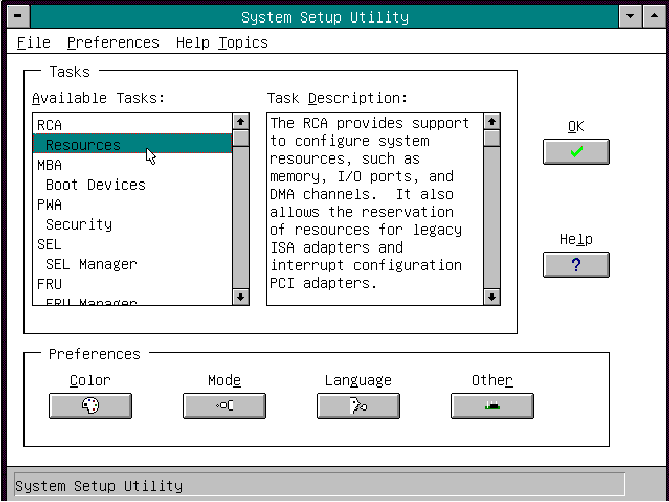
You can customize the UI according to your preferences. The AF sets these preferences and saves them in the AF.INI file so that they take effect the next time you start the SSU. Use these four user-customizable settings:
Color—lets you change the default colors associated with different items on the screen to predefined color combinations. The changes are instantaneous.
Mode—lets you set the desired expertise level.
Novice
Intermediate
Expert
The expertise level determines which tasks are visible in the Available Tasks section and what actions each task performs. For a new mode setting to take effect, you must exit the SSU and restart it. In the current implementation, there is no distinction between these three different modes.
Language—lets you change the text displayed in the SSU to the appropriate language. For a new language setting to take effect, you must exit the SSU and restart it.
Other—lets you change other miscellaneous options in the SSU. The changes are immediate.
To change the interface default values, do one of the following:
Use the mouse to click on the proper button in the Preferences section of the SSU Main window.
Use the Tab and arrow keys to highlight the desired button, and press the spacebar or Enter.
Access the menu bar with the mouse or hot keys (Alt + underlined letter).
| Note: If you run the SSU from non-writable media (like a CD-ROM), these preferences will be lost when you exit the SSU. |
It is possible to have many tasks open at the same time, although some tasks might require complete control to avoid possible conflicts. The tasks achieve complete control by commanding the center of operation until you close the task window.
To launch a task, do one of the following:
In the SSU Main window, double-click on the task name under Available Tasks to display the main window for that task.
Highlight the task name, and click OK.
Use the Tab and arrow keys to highlight the desired button, and press the spacebar or Enter.
The RCA provides three major functions:
Creates representations of devices that cannot be discovered by the system (ISA boards)
Modifies the contents of the system by adding and removing devices
Modifies the resources used by devices
You can use the RCA window to define or add an ISA board by clicking on the appropriate button. To remove an ISA board, highlight the board in the Devices section of the screen before clicking on the button. You can add only as many ISA boards as there are ISA slots available.
From the SSU main window, launch the RCA by selecting the Resources task under the RCA heading in the task box.
When the RCA window appears, it displays messages similar to the following:
Baseboard:  System Board
PCI Card: Bus 00 dev 00 -– Host Processor Bridge
PCI Card: Bus 00 dev 0D –- Multifunction Controller
PCI Card: Bus 00 dev 0F –- Ethernet Controller
PCI Card: Bus 00 dev 12 –- Multifunction Controller
PCI Card: Bus 00 dev 14 –- VGA Controller
To configure a device, click on it or select its name in the Devices section of the RCA window and press the spacebar or Enter.
You can close the RCA window and return to the AF by clicking on the Close button. Any changes made will be kept in memory for use by the RCA when it is rerun.
Save all changes by clicking Save. Saving writes your current configuration to nonvolatile storage where it will be available to the system after every reboot.
Closing the window by clicking on the system menu (the dash in the upper-left corner) discards all changes.
An ISA board usually comes with a vendor-created .CFG file that specifies the resources the card requires to function properly. If the .CFG file is unavailable, you must manually create it or define the board through the SSU. Defining an ISA board consists of specifying the name of the board and the resources it consumes. This allows the RCA to consider the ISA board resource requirements when the RCA tries to resolve conflicts. BIOS also uses this information to configure hardware when the system is booted.
To add or remove ISA board resources, click on the appropriate resource buttons, select the desired value, and click Add or Remove.
After you complete the necessary information, click Save.
To edit a board, click Load to retrieve the board information. After making changes, click Save.
To create a board, click New.
To remove a current definition of a board, click Delete.
Adding and removing boards through the RCA provides a way for the RCA to run its conflict detection algorithms on the resources requested by the boards. This alerts you to any possible problems with that particular board in the current configuration.
Click Add ISA Board in the RCA window.
Specify the directory for the .CFG file.
Select the file and click OK.
Select a valid ISA board in the Devices section of the RCA window.
Click on Remove ISA Board.
Modifying the resources of a device may be necessary to accommodate certain operating system applications, and drivers. It may also be necessary to modify resources to resolve a conflict.
To modify the resources associated with a device:
Highlight the device in the Devices section of the RCA window.
Press the spacebar or Enter, or double-click on the entry.
This displays the functions of the selected device along with possible choices and the resources associated with those choices.
To make a modification:
Highlight the function in the Configuration window.
Press the spacebar or Enter, or double-click on the entry (this updates the choice and resource lists).
Press the Tab key to get to the choice list, and press Enter.
Use the arrow keys to select a proper choice, and press Enter again.
If the choice allows multiple possible values for a particular resource, use the hot key to select a resource and press the spacebar or double-click on the resource.
Select the desired resource, and click OK.
Click on Resource Use in the Configuration window to display the System Resource Usage window, which shows the resources each device consumes. This information is useful if a conflict occurs. Devices can be organized according to the resources you want to examine using the options in the Resource section of the screen. The resource information can also be written to a plain text file through this window.
In this window, you can change the boot priority of a device.
Select a device.
Press + to move the device up in the list (higher priority). Press - to move it down.
In this window, you can set the User and Administrator passwords and security options.
Click on User Password.
Enter the password in the first field.
Confirm the password by entering it again in the second field.
Click on User Password.
Enter the old password in the first field.
Enter the new password in the second field (or leave it blank to clear).
Confirm the password by entering it again in the second field (leave blank to clear).
Click on Administrator Password.
Enter the password in the first field.
Confirm the password by entering it again in the second field.
Click on Administrator Password.
Enter the old password in the first field.
Enter the new password in the second field (or leave it blank to clear).
Confirm the password by entering it again in the second field (leave blank to clear).
In the security options window, you can set the other security options:
Hot Key—sets a key sequence that puts the server into secure mode when the key is pressed.
Lock-Out Timer—sets an interval that puts the server into secure mode when no activity occurs during the interval.
Secure Boot Mode—forces the server to boot directly into secure mode.
Video Blanking—turns off the video when the server is in secure mode.
Floppy Write—controls access to the diskette drive when the server is in secure mode.
Reset/Power Switch Locking—controls the power and reset buttons when the server is in secure mode.
Clicking on the SEL add-in task brings up the SEL viewer add-in, which allows users to:
Examine SEL records via the BMC in hex or verbose mode
Examine SEL records by sensor or event type in hex or verbose mode
Examine SEL records from a previously stored binary file in hex or verbose mode
Save SEL records to a file in either text or binary form
Clear SEL entries from the non-volatile storage area
The SEL viewer's main window provides access to features of the add-in. Each option included on the main menu supports an accelerator key. Accelerator keys are indicated by an underlined letter in the text listing the option. The main window includes support to display the following information for each SEL entry: record identifier, event type, time stamp information, generator identifier, emv revision, sensor type, sensor number, and event description.
Figure 3-2 shows the SEL viewer main window.

Table 3-21 shows the SEL viewer menu options.
Menu | Options |
|---|---|
File | Open SEL: Views data from previously saved SEL file |
View | SEL Info: Displays information about the SEL (display only) |
Settings | Display Hex/Verbose: Toggles between Hex/interpreted mode of displaying the
SEL records |
Help | About: Displays the SEL Viewer version information |
In this window, you can:
Examine all SDR records through the BMC (in either Hex or Verbose mode)
Examine SDR records by Record type (in either Hex or Verbose mode)
Examine SDR records from a previously stored binary file (in either Hex or Verbose mode)
Save the SDR records to a file (in either text or binary form)
The SDR Manager can display SDR records in either raw form (hexadecimal) or in an interpreted, easy-to-understand textual form (verbose).
The SDR Manager's main window provides access to features of the add-in through menus. Each option included on the main menu supports an accelerator key. Accelerator keys are indicated by an underlined letter in the text listing the option.
Figure 3-3 shows the SDR Manager main window. The SDR Manager Menu lists the window's menus and options, see Figure 3-3 for an example.
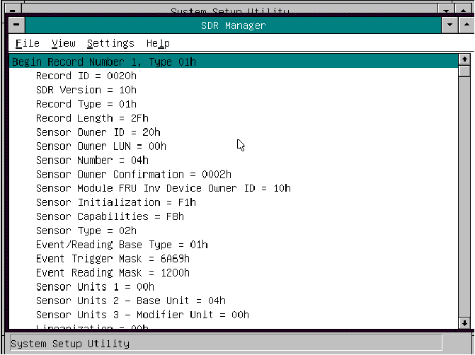
Table 3-22 lists the options available under the SDR manager menus.
Menu | Options |
|---|---|
File | Open FRU: Opens FRU data from a previously saved file |
View | SDR Info: Displays SDR information as returned by the GetSDRInfo interface of the
BMC |
Settings | Display HEX: Displays SDR records in Hex format |
Help | About: Displays SDR Manager version information |
In this window you can:
Examine all FRU Inventory areas on the server (in either Hex or Verbose mode)
Examine individual FRU Inventory areas (in either Hex or Verbose mode)
Examine FRU Inventory areas from a previously stored binary file (in either Hex or Verbose mode)
Save the FRU Inventory areas to a file (in either text or binary form)
The FRU Manager can display the FRU Inventory areas in either raw form (hexadecimal) or in an interpreted, easy-to-understand textual form (verbose). The FRU manager's main window provides access to features of the add-in through menus. Each option included on the main menu supports an accelerator key. Accelerator keys are indicated by an underlined letter in the text listing the option.
Figure 3-4 shows the FRU Manager main window. FRU Manager Menus lists the window's menus and options, see Figure 3-4 for an example.
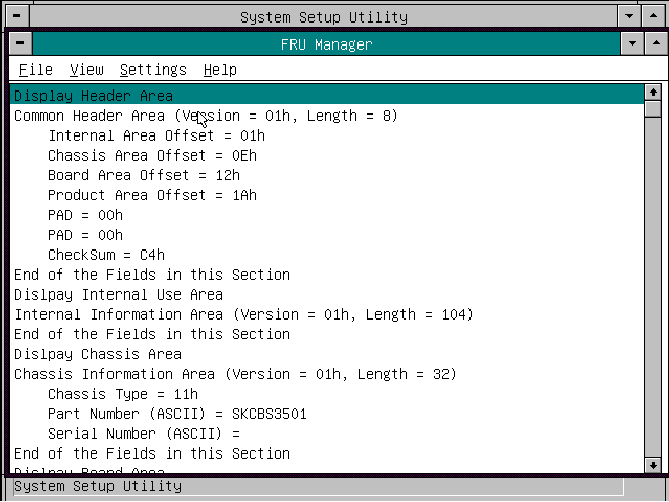
Table 3-23 describes the FRU manager menus and options.
Menu | Options |
|---|---|
File | Open FRU: Opens FRU data from a previously saved file |
View | FRU Info: Displays FRU information of the selected device |
Settings | Display HEX: Displays FRU areas in Hex format |
Help | About: Displays FRU Manager version information |
The EMP console provides an interface, called the console manager, to the EMP. This interface allows remote server management by way of a modem or direct connection. The EMP console is used only with a Windows operating system.
The following server control operations are available with the console manager:
Connecting to remote servers
Powering the server on or off
Resetting the server
Switching the server console between EMP active and BIOS re-direct modes
The console manager uses three management plug-ins to monitor the server: the SEL, SDR, and FRU viewers.
The console manager also has a support plug-in phonebook, which you can use to create and maintain a list of servers and their phone numbers. You can launch the Connect dialog directly from the Phonebook dialog to connect to a selected server.
The EMP shares the COM2 port with the system. When the EMP has control of the port, the port operates in command state. When the system has control of it, the port operates in redirect state. When connecting to a server, the EMP console checks to determine the current COM2 port state. See Figure 3-5 for and example screen of the EMP console in command state and Figure 3-6 for an example of the EMP console in redirect state.
Command state—the default COM2 state. In this state, the EMP console communicates with the server's firmware, allowing the client to remotely reset or power the server up or down. The client can also view the server's SEL, FRU information, or SDR table.
Redirect state—the EMP console serves as a PC ANSI terminal window for BIOS console redirection. Commands typed in this terminal window are transmitted through BIOS to the server's console, and text displayed on the server console is displayed on the EMP console's terminal window. With the EMP in this state, you can remotely view boot messages, access BIOS setup, and run DOS text mode applications through the EMP console's terminal window.
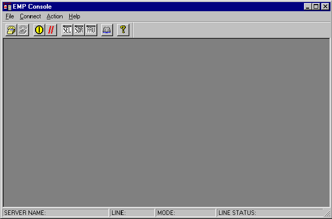
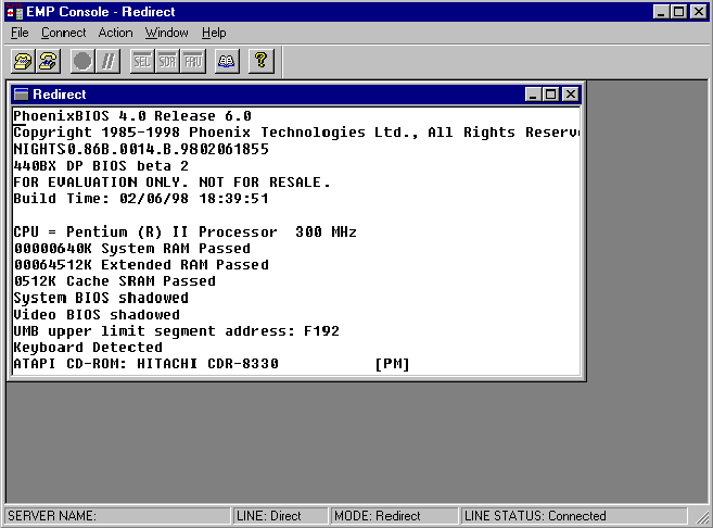
When you use the EMP console window in redirect state with the terminal window, the text that appears on the server monitor displays in the redirect window.
Availability of the various EMP console features is determined by two things:
the EMP access mode selected during configuration in the System Management Submenu of the BIOS Server Menu
whether the server's COM2 port is configured for console redirect in BIOS.
The three EMP access modes are disabled, pre-boot, and always active. See Table 3-24 for a listing of the access modes.
Table 3-24. EMP Console Access Modes (Server Configured for Console Redirect)
Mode | Server is powered off | During POST | After OS boots |
|---|---|---|---|
Disabled | Redirect window appears, but is blank | Redirect window | Redirect window |
Pre-boot | EMP commands available | Redirect window[a] | Redirect window |
Always Active | EMP commands available | Redirect windowa | EMP commands available |
[a] Note that you can modify the operation mode by selections in the POST reset and POST power-up dialogs. These are server control dialogs available with the EMP Console. | |||
Table 3-25 lists the access modes when the server is not configured for console redirection.
Table 3-25. EMP Console Access Modes (Server Not Configured for Console Redirect)
Mode | Server is powered off | During POST | After OS boots |
|---|---|---|---|
Disabled | Redirect window appears, but is blank | Redirect window appears, but is blank | Redirect window appears, but is blank |
Pre-boot | EMP commands available | EMP commands available | Redirect window appears, but is blank |
Always Active | EMP commands available | EMP commands available | EMP commands available |
This section outlines the requirements and configurations necessary for using the EMP console.
Operating System:
Windows NT
Windows NT 4.0 or later
24 MB of RAM, 32 MB recommended
20 MB disk space
Client Configuration: The EMP console will support all COM ports on the client system, along with any Windows NT compatible modem.
Server Configuration: The EMP console requires that the server's COM2 port be connected to an external modem or directly connected to a serial cable.
Direct Connect Configuration: A null modem serial cable is needed. Connect one end of the cable into the COM2 port of the server and the other into a port on the client machine.
Modem Configuration: On the client, the EMP console uses the Windows application program interface (API) to determine if a modem is connected and available. The EMP Console does not configure the modem; it should be preconfigured through Windows.
For modem support, the server must use a Hayes-compatible 14400 bps modem. The modem must be on the NT hardware compatibility list provided by Microsoft. The server modem must be set in autoanswer mode for the EMP console to be able to connect to it.
To use the EMP, you must configure BIOS with specific settings. Enter these settings in two submenus of the BIOS Server Menu: the System Management Submenu and the Console Redirect Submenu. The section above on BIOS settings shows all available options. The sections below focus on the settings that must be configured to use the EMP.
All EMP-related settings occur from the System Management Submenu of the server Main Menu. Change only the items below; all other default settings should remain the same.
EMP Password: Any time you attempt to initiate a connection, a prompt for the user password appears. If you never set up the EMP password, anyone can access the EMP by clicking OK through the password prompt.
In the EMP password area of the System Management Submenu, type in a password of up to eight alphanumeric characters. If the system beeps, the password was not accepted; you must enter a different password.
EMP Access Modes: Choose either disabled, pre-boot, or always active, depending on the type of EMP access needed. Table 3-24 and Table 3-25 list what is available with a given setting.
EMP Restricted Mode Access: Set restricted mode to either enabled or disabled. In enabled mode, the EMP console's server control options, Power On/Off and Reset, are NOT available. In disabled mode, these options ARE available.
EMP Direct Connect/Modem Mode: Select Direct Connect if a null modem serial cable directly connects the server's COM2 port to the EMP console client machine. If they are connected via a modem, select Modem Mode.
To use the EMP, you must set the following options exactly as noted.
COM Port Address: Select 2F8. This is the COM2 port that the EMP must use. The IRQ# setting is automatically assigned with the correct number based on the COM port address choice.
Baud Rate: Select 19.2k.
Console Type: Choose PC ANSI.
Flow Control: Choose CTS/RTS + CD.
The main EMP console window provides a graphical user interface (GUI) to access server control operations and to launch the management plug-ins. A menu and tool bar at the top of the GUI provide options to initiate plug-ins and other support features. A status bar at the bottom displays connection information like server name, line status, and mode.
The toolbar buttons combine server control and management plug-in options available from the Connect and Action Menus.
 | Connects to a selected server. |
 | Disconnects from the currently connected server. |
 | Powers the selected server on or off. |
 | Resets the selected server. |
 | Opens the SEL viewer. |
 | Opens the SDR viewer. |
 | Opens the FRU viewer. |
 | Opens the phonebook. |
 | Opens online help. |
The status bar displays at the bottom of the current window. It contains the following status information:
Server Name: The name of the connected server.
Line: The type of line connection (direct or modem).
Mode: Either redirect or EMP, depending on whether the EMP has control of the COM2 port.
Line Status: Gives status information on the server connection. For example, if a server is connected, the status bar says Connected. Otherwise, the line is blank.
File
Exit: Exits the EMP console.
Connect
Disconnect: Disconnects the server connection.
[Re]Connect: Raises the connect dialog.
(A list of the five most recent connections): Initiates connection to selected server.
Action
Power On/Off: Powers the server on or off with POST power-up options.
Reset: Resets the server with POST reset options.
SEL Viewer: Opens the SEL viewer.
SDR Viewer: Opens the SDR viewer.
FRU Viewer: Opens the FRU viewer.
Phonebook: Opens the phonebook dialog.
Help: Provides version information and help topics for the EMP console.
Three server control operations are available from the menu or toolbar of the main EMP console window, remote server connection, powering the server on and off, and resetting the server. The server console mode can also be switched between EMP active and BIOS redirect modes through POST power-up and reset options.
Select [Re]Connect from the Connect Menu and follow the Connect dialog. Connect Dialog allows you to connect to a selected server, see Figure 3-7. If the client machine is already connected to a server, initiating connection generates a warning message. The message states that the existing connection will be terminated if you continue trying to initiate the new connection. You are prompted to enter the EMP password whenever a connection is attempted.
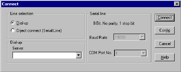
Options available in the dialog are:
Line Selection: Allows distinction between direct or dial-up modem connection to the server.
Dial-up: Connects to a selected server with a modem.
Direct connect (Serial Line): Connects to the selected server directly using a null modem serial cable.
Server: Displays a list of available servers in a drop-down edit list box. You can select or enter a server name; a server must be selected wen the line selection is dial-up.
Serial Line: Must be filled out when the line selection is set to direct connect (serial line).
Baud Rate: Specifies baud rate; must be 19200 for EMP to connect properly.
COM Port No.: Sets the COM port number to which the null modem serial cable is connected.
Connect: Initiates connection to the server. When you click this button, you are prompted for the EMP password.
Config: Displays the Phonebook dialog.
Cancel: Exit the Connect dialog with no action taken.
Help: Display dialog-level help information.
Selecting Power On/Off from the Action Menu allows you to power the server on or off, with POST power–on options. It generates the Power on/off dialog. See Figure 3-8 for an example.
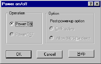
Options available in the dialog are:
Power ON: Powers on the server.
Power OFF: Powers off the server. This option is not allowed if the server is configured in restricted mode for EMP operations.
Post-power-up option: Sets the server mode EMP active or BIOS redirection. The setting is effective at the next power-up. The default selection is EMP active.
Cancel: Exits the dialog with no action taken.
Help: Displays dialog-level help information.
Selecting Reset from the Action Menu generates the Reset dialog so that you can remotely reset the server with POST reset options.
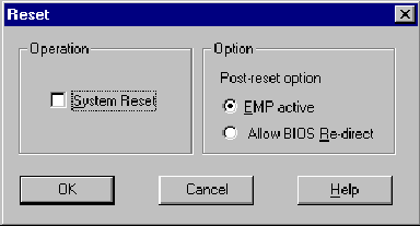
Options available in the dialog are:
System Reset: Resets the server with the selected POST reset options. This operation is not allowed if the server is configured in restricted mode for EMP operations.
Option Group: Sets the POST reset option that will be effective after reset. The options are EMP active or BIOS redirection. The default selection is EMP active.
Cancel: Exits the dialog with no action taken.
Help: Displays dialog-level help information.
The EMP console provides a phonebook, a support plug-in that stores names and numbers of servers in a list that can be updated by adding, modifying, or deleting entries. You can open the phonebook from the Main Menu and tool bars, or launch it by clicking the Config button.
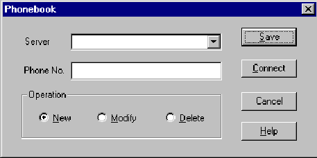
Options available in the dialog are:
Server: Displays a drop-down list of server names previously stored in the phonebook. If the New radio button is selected in the Operation area, the server area is cleared.
Phone No.: Displays the number of the selected server. If the New radio button is selected in the Operation area, this area is cleared.
Operation
New: Makes a new entry in the phonebook. Selecting this option clears the Server and Phone No. fields. You must click Save to add the entry to the phonebook.
Modify: Edits an existing entry. Before selecting this option, you must first select an existing entry from the Server drop-down edit box and modify the existing phone number. Click on Save to store this entry in the phonebook.
Delete: Deletes an entry from the phonebook. You must first select an existing server from the Server drop-down edit box before selecting this option. Click Save to delete the entry.
Save: Saves a new or modified phonebook entry or deletes an entry if you have already selected the Delete radio button.
Connect: Raises the Connect dialog with the server from the phonebook's Server drop-down edit box already populating the Connect dialog's Server drop-down edit box.
Cancel: Exits the dialog with no action taken.
Help: Displays dialog-level help information.
The following subsections list information on the SEL viewer and its options.
The SEL viewer can display records in either hexadecimal or text (verbose) form. These options are available through the SEL viewer:
View the SEL from a file
Save the SEL to a file
View SEL summary information
View all SEL entries
View SEL info by event type
View SEL info by sensor type
Set SEL display mode to either Hex or verbose mode
Set the SEL output file format to either text or binary format
Close the SEL viewer
Exit the EMP console
The following menu options are available on the SEL viewer menu bar:
File
Open: Allows you to view SEL data from a previously saved file if it was stored in binary format. Selecting the Open Menu item lets you specify a filename under which the data are found. The default filename is SELLOG.DAT. If the file cannot be opened, the program displays an error message.
Close: Closes the SEL viewer.
Save As: Dumps the SEL data to a file in either binary raw or verbose text format. The binary file can be retrieved later. Selecting this option lets you specify a filename to which the data can be saved. The default filename is SELLOG.DAT. If no data exist, an error message displays.
Exit: Exits the EMP console.
SEL Information: Displays SEL summary information.
All Events: Displays all events in the SEL.
By Sensor Type: Displays all events in the SEL generated by a specific sensor type, such as voltage, temperature, etc.
By Event: Displays all events in the SEL of a particular type, for example, by memory or threshold. A pop-up menu lets you select the event type to display. This menu displays all event types that can be generated by the particular hardware.
Settings: Lets you change several operating parameters for the SEL viewer. This menu displays the following suboptions:
Display HEX/Verbose: Toggles between HEX mode and interpreted mode of displaying SEL records.
Output Text/Binary: Specifies whether SEL data will be saved to the file in binary format or verbose format.
Window: Gives options for displaying currently open windows.
Help: Provides version information for the SEL viewer and provides help topics on the EMP console.
The SDR viewer lets you view the records retrieved from the SDR repository. Options available through the SDR viewer are:
View all SDR records
View SDR entries by SDR type
View SDR summary information
Set SDR display mode to either Hex or verbose mode
Close the SDR viewer
Exit the EMP console
The SDR viewer menu bar contains the following:
File
Close: Closes the SDR viewer.
Exit: Exits the EMP console.
View
Display all Records: Displays all records from the SDR repository.
SDR Type: Displays the records of a particular SDR type. You select an SDR type from a pop-up menu that displays all the SDR types available for the given hardware.
SDR Info: Displays the SDR summary information.
Settings: Lets you change operating parameters for the SDR viewer. This menu displays the following suboption:
Display HEX/Verbose: Toggles between HEX mode and interpreted mode of displaying SDR records.
Window: Gives options for displaying currently open windows.
Help: Provides version information for the SDR viewer and provides help topics on the EMP console.
The FRU viewer lets you view data from the server's baseboard FRU information area. Options available with the FRU viewer are:
View all FRU records
View FRU summary information
Set FRU display mode to either Hex or verbose mode
Close the FRU viewer
Exit the EMP console
The following menu options are on the FRU viewer menu bar:
File
Close: Closes the FRU viewer.
Exit: Exits the EMP console.
View
Display all Records: Displays all FRU data, which consist of chassis, board, and product information.
FRU Info: Displays the FRU summary information.
Settings: Lets you change operating parameters for the FRU viewer. This menu displays the following suboption:
Display HEX/Verbose: Toggles between HEX mode and interpreted mode of displaying FRU records.
Window: Gives options for displaying currently open windows.
Help: Provides version information for the FRU viewer and provides help topics on the EMP console.
The Field Replacement Unit (FRU) and Sensor Data Record (SDR) load utility is a DOS-based program used to update the server management subsystem's product level FRU, SDR, and the Desktop Management Interface (DMI) nonvolatile storage components (EEPROMs). The utility:
Discovers the product configuration based on instructions in a master configuration file
Displays the FRU information
Updates the EEPROM associated with the Baseboard Management Controller (BMC) that holds the SDR and FRU area
Updates the DMI FRU area located in the BIOS nonvolatile storage device
Generically handles FRU devices that might not be associated with the BMC
You should run the FRUSDR load utility each time you upgrade or replace the hardware in your server, excluding add-in boards, hard drives, and RAM. For example, if you replace an array of fans, you need to run the utility. It programs the sensors that need to be monitored for server management.
Because the utility must be reloaded to properly initialize the sensors after programming, turn the server off and remove the AC power cords from the server. Wait approximately 30 seconds, then reconnect the power cords and turn on the server.
You can run the utility directly from the configuration software CD or from diskettes you create from the CD.
If you choose to run the FRUSDR Load Utility from a diskette, you must copy the utility from the CD and follow the instructions in the included README.TXT file.
If your diskette drive is disabled, or improperly configured, you must use BIOS Setup to enable it. If necessary, you can disable the drive after you are done with the FRUSDR utility.
The utility:
Is compatible with ROM-DOS Ver. 6.22, MS-DOS Ver. 6.22, and later versions
Accepts CFG, SDR, and FRU load files (the executable file for the utility is frusdr.exe)
Requires the following supporting files
one or more .fru files describing the system's field replaceable units
a .cfg file describing the system configuration
an .sdr file describing the sensors in the system
The basic command line format is
frusdr [-?] [-h] [-d {dmi, fru, sdr}] [-cfg filename.cfg] [-fru filename.fru]
|
Table 3-26 lists the FRUSDR commands and describes them.
Table 3-26. FRUSDR Command Line Format
Command | Description |
|---|---|
frusdr | Is the name of the utility |
-? or -h | Displays usage information |
-d {dmi, fru, sdr} | Displays requested area only |
-cfg filename.cfg | Uses custom CFG file |
-p | Pause between blocks of data |
-v | Verbose, display any additional details |
The FRUSDR load utility allows only one command line function at a time. A command line function can consist of two parameters. Example: -cfg filename.cfg. Invalid parameters cause an error message and exit the program. You can use either a slash (/) or a minus sign (-) to specify command line options. The -p and -v flags can be used with any of the other options.
When the utility is run with the -? or -h command line flags, the following message is displayed when the verbose flag -v is added to the help command:
FRU & SDR Load Utility Version 2.1 Revision R.1.1 |
Usage: |
frusdr |
|
| -? or -h |
Displays usage information |
| -d {dmi,fru,sdr} |
Only displays requested area. |
| -cfg filename.cfg |
Uses custom CFG file. |
| -p |
Pause between blocks of data. |
| -v |
Verbose, display any additional details. |
Copyright (c) 1999, Intel Corporation, All Rights Reserved
This utility must be run from a system executing DOS. Running in a Windows DOS box is insufficient and will provide incorrect results. Programming the BMC FRU area clears the SDR table; therefore the SDR table must be reprogrammed. Upon completing the programming of the FRU and SDR areas, the server should be rebooted.
| Note: DOS users may alternatively use a '/' instead of the '-'. |
The following information displays if the -v option is included in the command line.
The /D FRU command may be followed with up to 16 device addresses. These device addresses are used to view up to 16 different FRU areas, instead of the default of displaying the BMC FRU. The arguments following the -d FRU are in the same order and value as the NVS_TYPE, NVS_LUN, DEV_BUS and DEV_ADDRESS which are found in the FRU file header in each FRU file. The LUN address is optional. If the LUN address is used, it must start with an L.
Usage: FRUSDR -d fru (device) [lun] (bus) (addr) (addr2) (etc)
Example: FRUSDR /D FRU IMBDEVICE L00 00 C0 C2
The configuration file may be used to load multiple FRU and SDR files. In the configuration file, you may define which FRU and SDR areas are to be programmed. Additionally, you may request information from the user or ask the user to choose which areas to program.
When the utility is run with the -d DMI, -d FRU, or -d SDR command line flag, the indicated area is displayed. Each area represents one sensor for each instrumented device in the server. If the given display function fails because of an inability to parse the data present or a hardware failure, the utility displays an error message and exits.
Displaying DMI Area
Each DMI area displayed is headed with the DMI area designated name. In each area, each field has a field name header followed by the field in ASCII or as a number.
Example:
To display the DMI area, type frusdr -d dmi and press Enter.
Displaying FRU Area
The FRU area is displayed in ASCII format when the field is ASCII or as a number when the field is a number. Each FRU area displayed is headed with the FRU area designated name. Each field has a field name header followed by the field in ASCII or as a number. The board, chassis, and product FRU areas end with an END OF FIELDS CODE that indicates there are no more data in the area. The internal use area is displayed in hex format, 16 bytes per line.
Example:
To display the FRU area, type frusdr -d fru and press Enter.
Displaying SDR Area
The SDR nonvolatile storage area is displayed in the following hex format. The data are separated by a sensor record number X header, where X is the number of that sensor record in the SDR area. The next line after the header is the sensor record data in hex format delineated by spaces. Each line holds up to 16 bytes. The data on each line are followed by the same data in ASCII format; note that nonprintable characters are substituted by a period (.).
Example:
To display the SDR area, type frusdr -d sdr and press Enter.
The utility can be run with the command line parameter of -cfg filename.cfg. The filename can be any DOS-accepted, eight-character filename string. The utility loads the specified CFG file and uses the entries in that file to probe the hardware and to select the proper SDRs to load into nonvolatile storage.
The utility displays its title:
FRU & SDR Load Utility, Version 2.0, Revision X.XX
where X.XX is the revision number for the utility.
The configuration file is in ASCII text. The utility executes commands formed by the strings present in the configuration file. These commands cause the utility to run tasks needed to load the proper SDRs into the nonvolatile storage of the BMC and possibly generic FRU devices. Some of the commands may be interactive and require you to make a choice.
Through the use of a configuration file, the utility might prompt you for FRU information.
The MASTER.SDR file has all the possible SDRs for the system. These records might need to be filtered based on the current product configuration. The configuration file directs the filtering of the SDRs.
After the utility validates the header area of the supplied SDR file, it updates the SDR repository area. Before programming, the utility clears the SDR repository area. The utility filters all tagged SDRs depending on the product configuration set in the configuration file. Nontagged SDRs are automatically programmed. The utility also copies all written SDRs to the SDR.TMP file, as it contains an image of what was loaded. The TMP file is also useful for debugging the server.
After the configuration is determined, the utility updates the FRU nonvolatile storage area. First it verifies the common header area and checksum from the specified FRU file. The internal use area is read out of the specified .FRU file and is programmed into the nonvolatile storage. The chassis area is read out of the specified .FRU file. Finally, it reads the product area out of the specified FRU file, then the area is programmed into the FRU nonvolatile storage. All areas are also written to the FRU.TMP file.
After programming the BMC FRU area, the utility programs the chassis, board, and product FRU information to the DMI fields. The update happens only if the DMI flag follows each FRUAREA command in the configuration file.
Before you change or upgrade the BIOS, prepare the system by recording the current BIOS settings, obtaining the upgrade utility, and making a copy of the current BIOS. Read the following subsections for information on these procedures.
Boot the computer and press F2 when you see the message:
Press F2 Key if you want to run SETUP
Write down the current settings in the BIOS Setup program.
| Note: Do not skip step 2. You will need these settings to configure your computer at the end of the procedure. |
You can upgrade to a new version of the BIOS using the new BIOS files and the BIOS upgrade utility, iFLASH.EXE. You can obtain the BIOS upgrade file and the iFLASH.EXE utility through your support provider or from the Intel World Wide Web site:
http://www.intel.com
| Note: Please review the instructions distributed with the upgrade utility before attempting a BIOS upgrade. |
This upgrade utility lets you:
Upgrade the BIOS in flash memory.
Update the language section of the BIOS.
The following steps explain how to upgrade the BIOS.
Use a DOS or Windows 95 system to create the diskette.
Insert a diskette in drive A.
At the C:\ prompt, for an unformatted diskette, type:
format a:/s
or, for a formatted diskette, type:
sys a:
Press Enter.
The BIOS upgrade file is a compressed self-extracting archive that contains the files you need to upgrade the BIOS.
Copy the BIOS upgrade file to a temporary directory on your hard disk.
From the C:\ prompt, change to the temporary directory.
To extract the file, type the name of the BIOS upgrade file, for example:
10006BI1.EXE
Press Enter. The extracted file contains the following files:
LICENSE.TXT
README.TXT
BIOS.EXE
Read the LICENSE.TXT file, which contains the software license agreement, and the README.TXT file, which contains the instructions for the BIOS upgrade.
Insert the bootable diskette into drive A.
To extract the BIOS.EXE file to the diskette, change to the temporary directory that holds the BIOS.EXE file and type:
BIOS A:
Press Enter.
The diskette now holds the BIOS upgrade and recovery files.
Boot the computer with the diskette in drive A. The BIOS upgrade utility screen appears.
Select Update Flash Memory From a File.
Select Update System BIOS. Press Enter.
Use the arrow keys to select the correct .bio file then press Enter.
When the utility asks for confirmation that you want to flash the new BIOS into memory, select Continue with Programming. Press Enter.
When the utility displays the message upgrade is complete, remove the diskette and press Enter.
As the computer boots, check the BIOS identifier (version number) to make sure the upgrade was successful.
To enter the Setup program, press F2 when you see the message:
Press F2 Key if you want to run SETUP
For proper operation, load the Setup program defaults. To load the defaults, press F9.
To accept the defaults, press Enter.
Set the options in the Setup program to the settings you wrote down before the BIOS upgrade.
To save the settings, press F10.
To accept the settings, press Enter.
Turn off the computer and reboot.
It is unlikely that anything will interrupt the BIOS upgrade; however, if an interruption occurs, the BIOS could be damaged. In that case, you must recover the BIOS.
| Note: Because of the small amount of code available in the noneraseable boot block area, there is no video support. You will not see anything on the screen during the procedure. Monitor the procedure by listening to the speaker and looking at the diskette drive LED. |
The procedure for recovering the BIOS is covered in the SGI 1400 Server Family Maintenance and Upgrades Guide. After doing the procedure, leave the upgrade disk in drive A and turn on the server, then continue with the BIOS upgrade.
You can use the BIOS upgrade utility to change the language BIOS displays. Use a bootable diskette containing the proper flash utility and language files.
Boot the computer with the bootable diskette in drive A. The BIOS upgrade utility screen appears.
Select Update Flash Memory From a File.
Select Update Language Set. Press Enter.
Select drive A and use the arrow keys to select the correct .lng file. Press Enter.
When the utility asks for confirmation that you want to flash the new language into memory, select Continue with Programming. Press Enter.
When the utility displays the message upgrade is complete, remove the diskette. Press Enter.
The computer will reboot and the changes will take effect.
The Firmware Update Utility is a DOS-based program used to update the BMC's firmware code. You need to run the utility only if new firmware code is necessary.
Create a DOS-bootable diskette. The version of DOS must be 6.0 or higher.
Place the firmware update utility (FWUPDATE.EXE) and the *.hex file on the diskette. Make a note of the *.hex filename, because you will need it later.
Insert the diskette into the drive and boot to it.
At the DOS prompt, run the executable file (FWUPDATE.EXE).
The utility will display a menu screen. Select Upload Flash.
The utility will ask for a filename. Enter the name of the *.hex file.
The program will load the file and then ask if it should upload boot block. Press N to continue.
The program will next ask if it should upload operational code. Press Y to continue.
Once the operational code has been updated and verified, press any key to continue. Then press Esc to exit the program.
Shut the system down and remove any diskettes in the system.
Disconnect all AC power cords from the system and wait 60 seconds.
Reconnect the AC power cords and power up the system.
After configuring the system, you need to install video drivers to take full advantage of the features of the onboard CL–GD5480 super VGA video controller.
The NT configuration software CD includes video drivers for use with DOS and Windows NT. Check the README.TXT file on the CD for information on installing these drivers.
For other operating systems, see your OS instructions for installing device drivers.