Table 2-1 lists the major features of the server system's processor board (also called the baseboard).
Table 2-1. Processor Board Features
Figure 2-2 shows the locations of the main components on the system processor board.
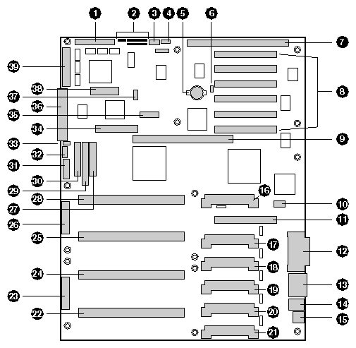
The components include:
Wide SCSI B connector (J9J1)
System jumpers (J6J1)
Hard drive input LED connector (J6J3)
System speaker connector (J6J2)
Lithium battery (B4H1)
Wake on LAN technology connector (J4H1)
ISA slot (J1J1)
PCI slots B4 (closest to ISA), B3, B2, B1, A3, and A2 (farthest from ISA)
Memory module connector (J3G1)
ICMB connector (J1E1)
PCI slot A1 (J2D1)
Video and parallel port connectors (J1C1)
Serial port connector (J1B2)
Keyboard and mouse connectors (J1B1)
USB external connector (J1A1)
VRM connector for processor 4 (J4E1)
VRM connector for processors 4 and 3 (J4C2)
VRM connector for processor 3 (J4C1)
VRM connector for processor 2 (J4B1)
VRM connector for processors 2 and 1 (J4A2)
VRM connector for processor 1 (J4A1)
Processor 1 Slot 2 connector (J9A1)
Main power connector, primary (J9B1)
Processor 2 Slot 2 connector (J9B2)
Processor 3 Slot 2 connector (J9D1)
Main power connector, secondary (J9D2)
Front panel connector (J8E1)
Processor 4 Slot 2 connector (J9E1)
IDE connector (J9E2)
Diskette drive connector (J9E3)
Auxiliary power connector (J9E4)
USB internal header (JC9F14)
SMBus connector (J9F2)
F16 expansion connector (J7G1)
ITP connector (J6G1)
Narrow SCSI connector (J9H1)
External IPMB connector (J7H1)
SMM connector (J8H1)
Wide SCSI A connector (J9H2)
Each Pentium III Xeon processor is packaged in a single edge contact (S.E.C.) cartridge. The cartridge includes the processor core with an integrated 16 KB primary (L1) cache; the secondary (L2) cache; a thermal plate; and a back cover.
The processor implements the MMX technology and it has a numeric coprocessor that significantly increases the speed of floating-point operations and complies with ANSI/IEEE standard 754-1985.
Each S.E.C. cartridge connects to the processor board through a 330-pin Slot 2 edge connector. The cartridge is secured by a retention module attached to the processor board. Depending on configuration, your system has one to four processors.
The processor external interface is MP-ready and operates at 100 MHz. The processor contains a local APIC unit for interrupt handling in multiprocessor (MP) and uniprocessor (UP) environments.
The L2 cache is located on the substrate of the S.E.C. cartridge. The cache:
Includes burst pipelined synchronous static RAM (BSRAM)
Is offered in 512 KB, 1 MB, and 2 MB configurations
Has error checking and correction (ECC)
Operates at the full core clock rate
Main memory resides on an add-in board, called a memory module, designed specifically for the SGI 1400 server. The memory module contains slots for 16 DIMMs, each of which must be at least 64 MB, and is attached to the processor board through a 242-pin connector. Memory amounts from 256 MB to 4 GB of DIMM are supported, with a 64/72-bit four–way–interleaved pathway to main memory, which is also located on the module. The 16 slots are divided into four banks of four slots each, labeled A through D. These banks support 4:1 interleaving. The memory controller supports EDO DRAMs. The ECC used for the memory module is capable of correcting single-bit errors (SBEs) and detecting 100 percent of double-bit errors over one code word. Nibble error detection is also provided. Figure 2-2 shows the installation sequence for the memory modules.
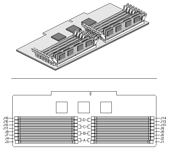
The first four module group installs in memory bank A, the second in bank B, the third in bank C and the last in Bank D.
System memory begins at address 0 and is continuous (flat addressing) up to the maximum amount of DRAM installed (exception: system memory is noncontiguous in the ranges defined as memory holes using configuration registers). The system supports both base (conventional) and extended memory.
 | Note: Addressable memory can be extended to 64 GB under certain configurations, but this server is configured to support 4 GB. |
Some operating systems and application programs use base memory while others use both conventional and extended memory. Examples:
Base memory: Windows NT and LINUX
Conventional and extended memory: Windows NT and LINUX
MS-DOS does not use extended memory; however, some MS–DOS utility programs like RAM disks, disk caches, print spoolers, and windowing environments use extended memory for better performance.
BIOS automatically detects, sizes, and initializes the memory array, depending on the type, size, and speed of the installed DIMMs, and reports memory size and allocation to the system via configuration registers.
In a 4 GB configuration, a small part of memory (typically 32 MB) is not remapped above 4 GB. If your operating system does not support more than 4 GB of physical memory, this small part of the memory is effectively lost.
| Note: Use DIMMs that have been tested for compatibility with the processor board. Contact your sales or support representative for a list of approved DIMMs. Table 2-2 lists some sample size combinations. |
Table 2-2. Sample DIMM Component Combinations
|
| Bank C | Bank D |
|
|---|---|---|---|---|
4 × 64 |
|
|
| 256 MB |
4 × 64 | 4 × 64 |
|
| 512 MB |
4 × 64 | 4 × 64 | 4 × 64 | 4 × 64 | 1024 MB |
4 × 256 |
|
|
| 1024 MB |
4 × 256 | 4 × 256 |
|
| 2048 MB |
4 × 256 | 4 × 256 | 4 × 256 | 4 × 256 | 4096 MB |
The following subsections provide a description of the peripheral control devices on the processor board.
The 87309 device supports two serial ports, one parallel port, diskette drive, and PS/2-compatible keyboard and mouse. The system provides the connector interface for each port.
Both serial ports are relocatable. By default, port A is physically the top connector, port B on the bottom. Each serial port can be set to one of four different COMx ports, and each can be enabled separately. When enabled, each port can be programmed to generate edge- or level-sensitive interrupts. When disabled, serial port interrupts are available to add-in boards.
The 25/15-pin connector stacks the parallel port over the VGA. The 87309 provides one IEEE 1284-compatible 25-pin bidirectional EPP (supporting levels 1.7 and 1.9). BIOS programming of the 87309 registers enables the parallel port and determines the port address and interrupt. When disabled, the interrupt is available to add-in boards.
The processor board (also called a baseboard) has one ISA slot that is full-length if the wide SCSI-B slot is not used (and half-length if the wide SCSI-B slot is used); the ISA slot supports slave-only boards and is shared with PCI-B slot 4. The ISA has three embedded devices: the Super I/O device, Baseboard Management Controller (BMC), and flash memory for system BIOS. ISA features include:
Bus speed up to 8.33 MHz
16-bit memory addressing
Type A transfers at 5.33 MB/sec
Type B transfers at 8 MB/sec
8- or 16-bit data transfers
Plug and Play ready
The processor board has two 32-bit PCI bus segments: PCI-A and PCI-B. These provide seven slots for PCI add-in boards: three on PCI-A and four on PCI-B. PCI-B4 is shared with the ISA slot. PCI–A1 supports half-length boards only. The other slots support full-length boards. PCI features:
33 MHz bus speed
32-bit memory addressing
5 V signaling environment
Burst transfers of up to 133 MB/sec
8-, 16-, or 32-bit data transfers
Plug and Play ready
Parity enabled
The onboard, integrated Cirrus Logic CL-GD5480 64-bit VGA ASIC contains an SVGA controller that is fully compatible with these video standards: CGA, EGA, Hercules Graphics, MDA, and VGA. The standard system configuration comes with 2 MB of 10 ns onboard video memory. The video controller supports pixel resolutions of up to 1600 x 1200 and up to 16.7 M colors.
The SVGA controller supports analog VGA monitors (single and multiple frequency, interlaced and noninterlaced) with a maximum vertical retrace noninterlaced frequency of 100 Hz.
You cannot add video memory to this system. Depending on the environment, the controller displays up to 16.7 M colors in some video resolutions. It also provides hardware-accelerated bit block transfers (BITBLT) of data.
The processor board includes two SCSI controllers. A narrow SCSI controller (SYM53C810AE) is on the PCI-A bus, and a dual-channel wide LVD/SE (Ultra2/Ultra) SCSI controller (SYM53C896) is on the PCI-B bus. The narrow provides support for the legacy 8-bit SCSI devices in the 5.25-inch drive bays. The wide drives one SCSI backplane and provides support for external expansion.
Internally, each wide channel is identical, capable of operations using either 8- or 16-bit SCSI providing 10 MB/sec (Fast-10) or 20 MB/sec (Fast-20) throughput, or 20 MB/sec (Ultra), 40 MB/sec (Ultra-wide) or 80 MB/sec (40 Mhz) (Ultra-2).
The SYM53C810AE (narrow) contains a high-performance SCSI core capable of Fast 8-bit SCSI transfers in single–ended mode. It provides programmable active negation, PCI zero wait-state bursts of faster than 110 MB/sec at 33 MHz, and SCSI transfer rates from 5 to 10 MB/sec. The narrow SCSI comes in a 100-pin rectangular plastic quad flat pack (PQFP) and provides an “AND tree” structure for testing component connectivity.
The Sym53C896 (wide) contains a high-performance SCSI bus interface. It supports SE mode with 8–bit (10 or 20 MB/sec) or 16-bit (20 or 40 MB/sec) transfers and LVD mode with 8-bit (40 MB/sec) or 16-bit (80 MB/sec) transfers in a 329-pin ball grid array (BGA) package.
Each controller has its own set of PCI configuration registers and SCSI I/O registers. As a PCI 2.1 bus master, the SYM53C896 supports burst data transfers on PCI up to the maximum rate of 132 MB per second using on-chip buffers.
In the internal bay, the system supports up to six one–inch SCSI hard disk drives, plus, in the 5.25-inch removable media bays, three SCSI or IDE devices (the controller itself supports more devices, but the 5.25-inch bay can contain a maximum of three devices). A wide SCSI cable provides two connectors for Ultra SCSI devices (one of these connectors is for the internal SCSI backplane). However, SCSI devices do not need to operate at the ultra transfer rate. All drives on the bus must be Ultra-2 (LVD) to run at 80 MB/sec (40 MHz). The 5, 10, and 20 MHz operations can coexist on the bus and each device will interact at its appropriate speed.
No logic, termination, or resistor loads are required to connect devices to the SCSI controller other than termination in the device at the end of the cable. The SCSI bus is terminated on the processor board with active terminators that can be disabled.
IDE is a 16-bit interface for intelligent disk drives with AT disk controller electronics onboard. The PCI/ISA/IDE Accelerator, called PIIX4E, is a multifunction device on the processor board that acts as a PCI-based Fast IDE controller. The device controls:
PIO and IDE DMA/bus master operations
Mode 4 timings
Transfer rates up to 22 MB/sec
Buffering for PCI/IDE burst transfers
Master/slave IDE mode
Up to two drives for one IDE channel
The PS/2-compatible keyboard and mouse connectors are mounted in a single-stacked housing with the mouse connector over the keyboard. External to the system, they appear as two connectors.
You can plug in the keyboard and mouse to either connector before powering up the system. BIOS detects these and configures the keyboard controller accordingly.
The keyboard controller is functionally compatible with the 8042A microcontroller. The system can be locked automatically if no keyboard or mouse activity occurs for a predefined length of time, if specified through the system setup utility (SSU). Once the inactivity (lockout) timer has expired, the keyboard and mouse do not respond until the previously stored password is entered.
Server Management features are implemented using one microcontroller on the processor board known as the Baseboard Management Controller (BMC).
The BMC and associated circuitry are powered from 5V_Standby, which means this device remains active even when system power is switched off.
The primary function of the BMC is to autonomously monitor system platform management events and log their occurrence in the nonvolatile System Event Log (SEL). These events include overtemperature and overvoltage conditions, fan failure, or chassis intrusion. While monitoring, the BMC maintains the nonvolatile sensor data record repository (SDRR), from which run-time information can be retrieved. The BMC provides an ISA host interface to SDRR information, so software running on the server can poll and retrieve the current status of the platform. A shared register interface is defined for this purpose.
SEL contents can be retrieved after system failure for analysis by field service personnel using system management tools like Intel LANDesk Server Manager. Because the BMC is powered by 5V_Standby, SEL (and SDRR) information is also available by way of the interperipheral management bus (IPMB). An emergency management board like the Intel LANDesk Server Monitor Module board can obtain the SEL and make it remotely accessible using a LAN or telephone line connection. During monitoring, the BMC performs the following functions:
Processor board temperature and voltage monitoring
Processor presence monitoring and FRB control
Processor board fan failure detection and indicator control
SEL interface management
Sensor Data Record Repository (SDRR) interface management
SDR/SEL timestamp clock
Processor board Field Replaceable Unit (FRU) information interface
System management watchdog timer
Periodic SMI timer
Front panel NMI handling
Event receiver
ISA host and IPMB interface management
Secure mode control, front panel lock/unlock initiation, and video blank and diskette write protect monitoring and control
Sensor event initialization agent
Wake on LAN via Magic Packet support
ACPI Support
Emergency Management Port (EMP) support
To help prevent unauthorized entry or use of the system, the system includes a three-position key lock/switch to permit selected access to drive bays (position is communicated to BMC). The system also includes server management software that monitors the chassis intrusion switch.
The system includes a chassis intrusion switch. When the access cover is opened, the switch transmits an alarm signal to the processor board, where server management software processes the signal. The system can be programmed to respond to an intrusion by powering down or by locking the keyboard, for example.
The SSU provides a number of security features to prevent unauthorized or accidental access to the system. Once the security measures are enabled, access to the system is allowed only after the user enters the correct password(s). For example, the SSU allows you to:
Enable the keyboard lockout timer so the server requires a password to reactivate the keyboard and mouse after a specified time-out period of 1 to 120 minutes
Set secure mode to prevent keyboard or mouse input and to prevent use of the front panel reset and power switches
Activate a hot-key combination to enter secure mode quickly
Disable writing to the diskette drive when secure mode is set
If you set and enable a user password but not an administrator password, enter the user password to boot the system and run the SSU.
If you set and enable both a user and an administrator password:
Enter either one to boot the server and enable the keyboard and mouse
Enter the administrator password to access the SSU or BIOS Setup to change the system configuration
Configure and enable the secure boot mode by using the SSU. When secure mode is in effect, you:
Can boot the system and the OS will run, but you must enter the user password to use the keyboard or mouse
Cannot turn off system power or reset the system from the front panel switches
Secure mode has no effect on functions enabled via the Server Manager Module or power control via the real-time clock (RTC).
Taking the system out of secure mode does not change the state of system power. That is, if you press and release the power switch while secure mode is in effect, the system will not power off when secure mode is later removed. However, if the front panel power switch remains depressed when secure mode is removed, the system will power off.
Table 2-3 lists the software security features and describes what protection each offers. In general, to enable or set the features listed here, you must run the SSU and go to the Security Menu (see “Security Menu” in Chapter 3).
Table 2-3 also refers to other SSU menus and to the Setup utility. For further details and information on these topics see Chapter 3.
Table 2-3. Server Software Security Features