Phillips (cross-head) screwdriver (#1 and #2 bit).
Small flat-bladed screwdriver.
Jumper removal tool or needle-nosed pliers.
Antistatic wrist strap and conductive foam pad (recommended).
Pen or pencil.
Equipment log: as you integrate new parts into the system, add information about them to your equipment log, see Appendix A. Record the model and serial number of the system, all installed options, and any other pertinent information specific to the system. You will need this information when running the SSU.
Before removing the access cover at any time to work inside the system, observe these safety guidelines.
Turn off all peripheral devices connected to the system.
Turn off the system by using the push-button on/off power switch on the front of the system.
Unplug the AC power cords from the system or wall outlet.
Label and disconnect all peripheral cables and all telecommunication lines connected to I/O connectors or ports on the back of the system.
Provide some electrostatic discharge (ESD) protection by wearing an antistatic wrist strap attached to chassis ground of the system—any unpainted metal surface—when handling components.
These warnings and cautions apply whenever you remove the access cover of the system. Only a technically qualified person should integrate and configure the system.

You need to remove the system access cover, and in some cases the front bezel, to reach components inside the system. Facing the front of the system, the access cover is on the right side for pedestal-mounted (tower) servers, and on the top for rack-mounted servers.
Observe the safety and ESD precautions at the beginning of this chapter.
Turn off all peripheral devices connected to the system.
If you have not already done so, turn off the system by using the power on/off switch on the front panel AND unplug all AC power cords.
Label and disconnect all peripheral cables attached to the I/O panel on the back of the system.
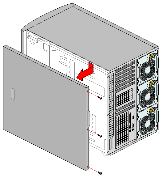
Remove and save the three screws from the back of the access cover; you will need them later to reattach the cover.

Note: Be sure the chassis key lock on the front of the system is in the unlocked position. Otherwise, you will be unable to remove the cover. The chassis keys are not all the same, you cannot use one key to open multiple units. Place the fingertips of your right hand under the built-in handle on the back of the cover. A rounded, rectangular depression in the front middle of the access cover serves as another handle.
Using an even pull, slide the cover backward, about an inch, until it stops.
Pull the entire cover outward, straight away from the chassis, to disengage the tabs from the notches in the top and bottom edges of the chassis. Set the cover aside.
Before replacing the access cover, check that you have not left loose tools or parts inside the system.
Check that cables, PCI option boards, and other components are properly installed.
Position the cover over the chassis so that the rows of tabs align with slots in the chassis. Slide the cover toward the front of the system until the tabs on the cover firmly engage in the chassis.
Attach the cover to the chassis with the three screws you removed earlier, and tighten them firmly (6.0 inch-pounds).
Connect all external cables and the power cords to the system.
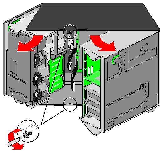
The chassis is comprised of three parts:
the main chassis
a swing-out subchassis at the front
a swing-out subchassis, called the electronics bay, at the rear
To access components in some instances, you must swing away and/or completely remove the subchassis and electronics bay.
Observe the safety and ESD precautions at the beginning of this chapter.
Turn off all peripheral devices connected to the system.
Turn off the system power by using the power on/off switch on the front panel AND unplug all AC power cords.
Label and disconnect all peripheral cables attached to the I/O panel on the back of the system.
Remove and save the three screws from the back of the access cover; you will need them later to reattach the cover.
Remove the access cover.
Remove the two screws on the top and bottom edges of the chassis (see Figure 1-2). These screws attach the front subchassis and the electronics bay to the main chassis.

Caution: You must disconnect all cabling to the electronics bay before rotating or removing the bay. Failure to do so can result in serious damage to system components. The location of the main connectors in the electronics bay is also shown in Figure 1-2. Rotate the front subchassis left, away from the main chassis, until it stops.
Disconnect and label all cabling to the electronics bay.
Using the vertical edge of the electronics bay as a handle, rotate the bay right, away from the main chassis, until it stops.
If necessary, completely remove the subchassis and electronics bay: this requires rotating the bays outward until the two pins that function as hinges for the bays slide out of their slots. Set the bays aside.
The information in this section covers installation of optional PCI boards.
Use the following steps to properly install a PCI option board:
Remove access cover.
Remove the PCI option board from its protective wrapper. Be careful not to touch the components or gold edge connectors. Place board component-side up on an antistatic surface.
Record the serial number of the PCI option board in your equipment log.
Set jumpers or switches according to the manufacturer's instructions.
Remove and save the screw that attaches the existing board or expansion slot cover to the chassis.
Hold the PCI option board by its top edge or upper corners. Firmly press it into an expansion slot on the baseboard. The tapered foot of the board retaining bracket must fit into the mating slot in the expansion slot frame. See Figure 1-3 for an example.
Install an ISA board component-side UP.
Install a PCI board component-side DOWN.
Use the screw removed earlier to fasten the new board retaining bracket to the chassis. Tighten the screw firmly (6.0 inch-pounds). Attach cables if necessary.
Reinstall the access cover using the original screws.
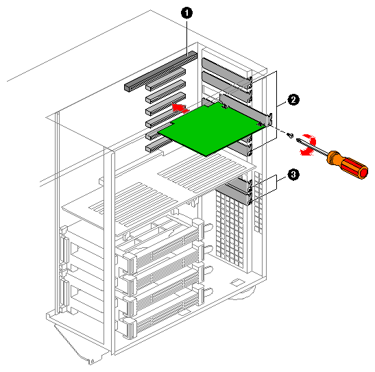
Components shown in Figure 1-3 are:
PCI or ISA slot
Six PCI slots (top to bottom in figure = PCI B4, B3, B2, B1, A3, and A2)
PCI slot A1 (Use five inch-length (12.7 cm) board only)
| Note: Slot covers must be installed on all vacant expansion slots. This maintains the electromagnetic emissions characteristics of the system and ensures proper cooling of system components. |
Read and observe the safety and ESD precautions listed at the beginning of this chapter.
Disconnect any cables attached to the board you are removing.
Remove and save the screw that attaches the existing board retaining bracket to the chassis.
Holding the board by its top edge or upper corners, carefully pull it out. Do not scrape the board against other components.
Store board in an antistatic protective wrapper.
If you are not reinstalling a board in the same slot, install a slot cover over the vacant slot. The tapered foot of the cover must fit into the mating slot in the expansion slot frame.
Use the screw removed earlier to fasten the new board to the chassis. Tighten the screw firmly (6.0 inch-pounds).
Running the SSU is optional after you remove a PCI or ISA board.
The front panel board contains the system controls and indicators. It is mounted on a snap-on standoff and a threaded standoff inside the chassis.
Observe the safety and ESD precautions at the beginning of this chapter.
Remove the access cover.
Disconnect the fan cables and remove the fan housing assembly, see Figure 1-4.
Disconnect the 3.5-inch diskette drive cables. Remove the diskette drive carrier from the chassis. Save the screw to use later.
On the front panel board, remove and save the screw from the threaded standoff to use later.
Grasp the front panel board. Carefully pull it toward the back of the system until it pops off the snap-on standoff.
Disconnect the front panel board signal cable from the front panel board.
Remove the front panel board from the system. Place it on an antistatic foam pad or a grounded work surface.
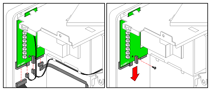
Reconnect the front panel board signal cable to the front panel board.
Position the front panel board over the snap-on standoff and the threaded standoff inside the chassis.
Carefully press the board onto the snap-on standoff until it snaps in place.
Reinstall and firmly tighten (6.0 inch-pounds) the screw that secures the board to the chassis.
Reinstall the 3.5-inch diskette drive carrier. Connect the drive cables.
Reinstall the access cover using the original screws.
Observe the safety and ESD precautions at the beginning of this chapter.
Remove the access cover.
Disconnect the power and signal cables from the diskette drive. The connectors are keyed for ease in reconnecting them to the drive, see Figure 1-5.
Remove and save the screw that secures the diskette drive carrier to the 5.25–inch drive bay.
Slide the carrier toward the back of the chassis to disengage the tabs from the slots in the bottom of the 5.25-inch drive bay.
Remove the carrier and drive assembly from the chassis, and place it component–side up on an antistatic surface.
Remove the drive from the carrier by sliding the drive forward, toward (and out of) the front of the carrier. Set the carrier aside.
Place the drive in an antistatic protective wrapper if you are not reinstalling the same drive.
Reinstall the access cover using the original screws.
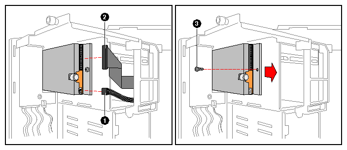
Components shown in Figure 1-5 are:
Power cable
Signal cable
Securing screw
Remove the new 3.5-inch diskette drive from its protective wrapper, and place it component–side up on an antistatic surface. Record the drive model and serial numbers in your equipment log.
Set any jumpers or switches according to the drive manufacturer's instructions.
Place the drive carrier on the component-side of the drive.
Attach the carrier to the drive by sliding the drive toward the closed/back end of the carrier. The drive is fully seated when it rests against the square brackets that form the back of the carrier.
Position the carrier so that the two protruding notches fit into the corresponding slits in the frame. Slide the assembly toward the front of the system to engage the notches. Make sure the front of the drive fits correctly in the front opening of the system. When properly positioned, the carrier notches extend slightly into the interior of the 5.25–inch drive bays and the threaded hole in the carrier aligns with the threaded hole in the frame.
Secure the assembly to the 5.25-inch bay with the screw you removed earlier; tighten the screw firmly (6.0 inch-pounds).
Connect the signal and power cables to the drive. The red stripe on the signal cable must face toward the center of the drive.
Reinstall the access cover using the original screws.
Run the SSU to specify that the diskette drive is installed in the system.
The following sections provide information on internally mounted drives and cables.
This section summarizes device cabling requirements and constraints. The number of devices you can install internally depends on:
The number supported by the bus
The number of physical drive bays available
The height of drives in the internal bays (1-inch or 1.6-inch high)
The combination of SCSI and IDE devices
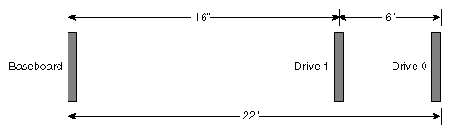
An 18-inch (45.7 cm) long IDE cable that supports two drives is standard in the system. If you install an IDE drive, we recommend placing it in the lowest 5.25-inch drive bay to make cabling easier.
For proper IDE operation, note the cable length specified in Figure 1-6. If no drives are present on an IDE channel, the cable must be removed. If only one drive is installed, it must be connected at the end of the cable.
One narrow and two wide SCSI cables are standard in the system.
All SCSI devices must be unterminated except the peripheral at the end of the SCSI cable. Hard drives usually provide an active termination, while CD–ROM drives do not. Because we recommend putting hard drives only in the internal bays, this means that you should route the SCSI cable so that the last device on the cable is a hard drive in the internal bay.
Three 5.25-inch half-height bays provide space for tape backup, CD-ROM, or other removable media drives. Note that system EMI integrity and cooling are both protected by having drives installed in the bays or filler panels and EMI shields covering the bays. When you install a drive, save the panel and shield to reinstall in case you should later remove the drive and not reinstall one in the same bay.
To maintain compliance with electromagnetic compatibility (EMC) regulations, the 5.25-inch bays must be configured with either:
An EMC-compliant 5.25-inch peripheral device, OR
A metal cover plate
It is important that your cabling and connections meet the SCSI bus specification. Otherwise, the bus could be unreliable and data corruption could occur or devices might not work at all. The SCSI bus needs to be terminated at the end of the cable; this is usually provided by the last SCSI device on the cable.
Use the following steps when installing a 5.25-inch peripheral:
Observe the safety and ESD precautions at the beginning of this chapter.
Open the front bezel by rotating its right side out and to the left.
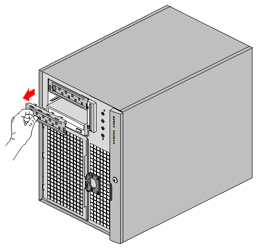
Caution: To avoid damage to a 5.25-inch peripheral device, ensure the EMI gasketing provided in the lower bay does not bridge or short any open circuits of the exposed peripheral device. If the 5.25-inch device has open circuits, install it in one of the two upper bays. Put a finger in the hole and pull the EMI metal shield out to disengage it from the chassis, see Figure 1-7. Save the shield.
Remove the drive from its protective wrapper, and place it on an antistatic surface.
Record the drive model and serial numbers in your equipment log.
Set any jumpers or switches on the drive according to the drive manufacturer's instructions.
Using two screws of the appropriate size and length (not supplied), attach each plastic slide rail with its metal grounding plate to the drive, see Figure 1-8.
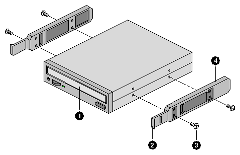
The components shown in Figure 1-8 are:
Tape drive or other removable media device
Tab on slide rail
Screws (quantity 4)
Slide rails (quantity 2)
Complete the installation of the new 5.25-inch drive using the following steps:
Position the drive so the plastic slide rails engage in the bay guide rails. Push the drive into the bay until the slide rails lock in place.
Connect a power cable to the drive. The connectors are keyed and can be inserted in only one way.
Connect a signal cable to the drive. The connectors are keyed and can be inserted in only one way.
SCSI drive: Attach connectors on the cable to the SCSI device or devices you are installing.
IDE drive: The baseboard has one IDE connector. It can support an IDE signal cable up to 22 inches long. See “Drive Cabling Considerations” for the cable dimensions.
Close the front bezel.
Observe the safety and ESD precautions at the beginning of this chapter.
Open the front bezel by rotating its right side out and to the left.
Disconnect the power and signal cables from the drive.
The drive has two protruding plastic, snap-in rails attached. Squeeze the rail tabs toward each other as you carefully slide the drive forward out of the bay, and place it on an antistatic surface.
Remove and save the four screws and two slide rails.
If you leave the bay empty, install a stainless steel EMI shield on the bay for proper cooling and airflow.
If you do not replace the device with another SCSI device, and it was installed at the end of the SCSI signal cable, modify the cable and termination arrangement so that a proper termination exists at the end of the cable (it can be a termination device only, not necessarily a SCSI peripheral).
Close the front bezel.
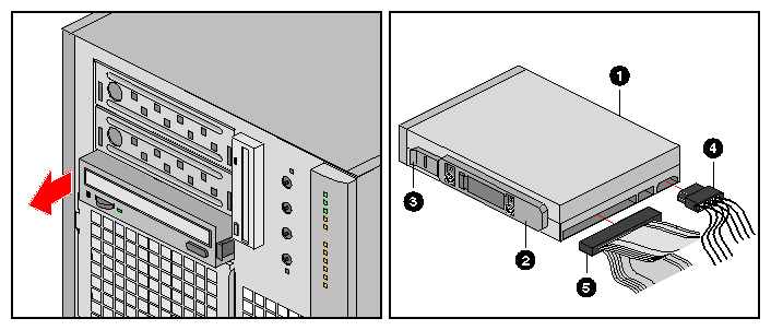
Components shown in Figure 1-9 are:
Removable media device
Drive rail
Rail tab
Power cable
Typical SCSI signal cable
The cable for channel B has two labels. The channel B cable connects from the SCSI-B connector on the baseboard to one of the external ports at the back of the server. If you are uncertain which connector on the baseboard is SCSI B, see Figure 4-1 in Chapter 4, “Technical Reference.”
Before you install or replace the SCSI-B cable, read and heed all the safety warnings at the beginning of this chapter. After you shutdown the system, unplug all AC power cords from the system power supplies or the wall outlets. You may also need to disconnect all peripheral cables and telecommunication lines connected to I/O connectors or ports on the back of the system (especially in rackmount units). Use the following steps to install or replace the cable:
Remove the system access cover and carefully take out the rear foam cover.
If desired, you can remove the front foam cover and unscrew and swing out the front subchassis.
Remove the memory module.
Remove any existing SCSI-B cable if it is defective or damaged.
Attach the new or replacement SCSI-B cable to the SCSI-B connector on the baseboard. Leave the cable unconnected at the other end.
Reinstall the memory module.
Remove one of the two knock-out covers, or remove the existing external SCSI-B connection if installed. See Figure 1-10 at the back of the system. If the server is upright in pedestal mode, the two covers are at the bottom left, to the left of the I/O panel.
Place the tip of a flat-blade screwdriver, or the end of another suitable tool, in the slot in the center of the knock-out cover.
Rotate, twist, etc., the screwdriver until you free the cover by breaking the small metal tab that holds the cover to the chassis. Be sure to remove covers that fall into the chassis.
Attach the cable connector to one of the ports at the back of the system as indicated in Figure 1-10; note where the cable exits the foam and in the expanded detail, where the cable attaches to one of the ports.
Use two screws (included) to secure the connector.
Reinstall the back foam cover. As you do, position the SCSI cable so that it routes to the electronics bay through the cutout in the back foam cover. The dotted arrow in Figure 1-10 shows where the cable must go.
Position the cable along the recess in the back foam cover.
Reinstall the access cover using the original screws.
Connect all AC power and peripheral device cables to the back of the system.
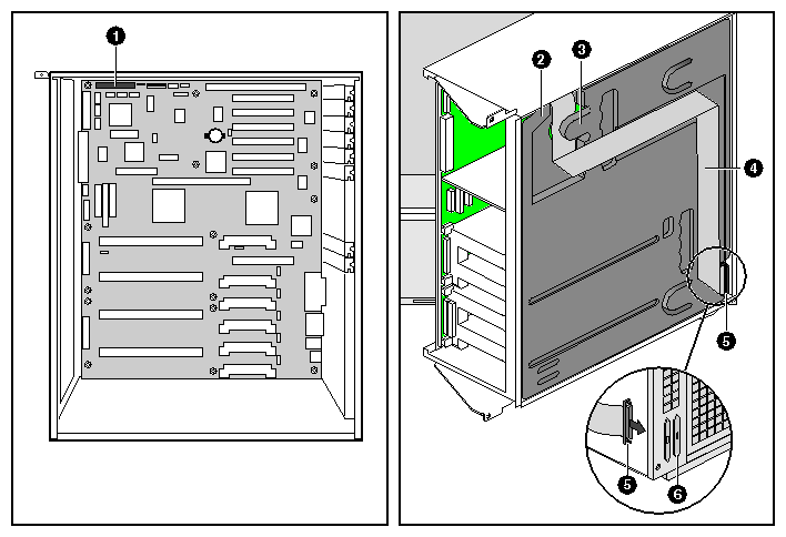
The components shown in Figure 1-10 are:
SCSI-B connector on the baseboard
Rear foam cover
Foam tab
SCSI-B cable (fit along recess in foam cover)
External SCSI-B connection
SCSI knockout cover
The SGI 1400 server contains eight removable chassis fans that cool the boards and removable media drives. These chassis fans connect to the front panel board and are enclosed in a removable foam assembly. The three integrated power supply fan(s) provide more cooling and airflow.
Use the following steps and Figure 1-11 to remove the system fan assembly:
Observe the safety and ESD precautions at the beginning this chapter.
Remove the access cover.
Remove the foam cover from the front subchassis by pulling it straight out.
For better access to the individual fan cables on the front panel board, carefully rotate the right edge of the foam fan assembly outward into the opening where the foam cover was.
Label and disconnect the individual fan cables from the front panel board.
Remove the fan assembly from the chassis.
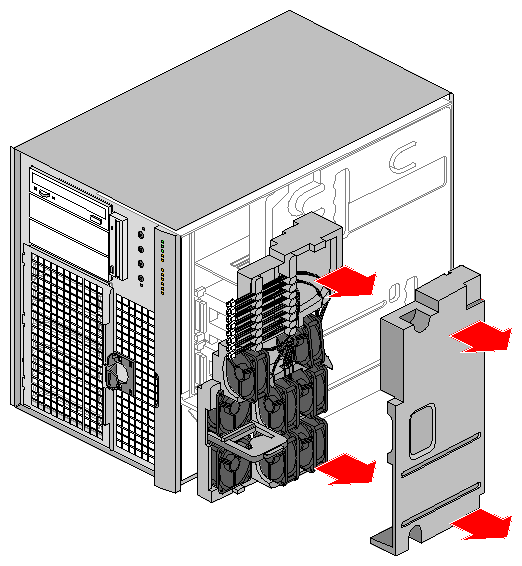
Observe the safety and ESD precautions at the beginning this chapter.
Position the fan assembly inside the chassis so that the individual fan cables can easily reach their connectors on the front panel board.
Reconnect the individual fan cables, being careful to match each cable with its correct connector on the front panel board.
Position the fan assembly as it was inside the chassis prior to removal, so that it rests firmly against the diskette drive at the top and the 5.25-inch bays at the middle and bottom.
Reinstall the foam cover. It is molded to match the position of the fans and fits in only one way.
Reinstall the access cover using the original screws.
Observe the safety and ESD precautions at the beginning this chapter.
Remove the access cover.
Remove the foam cover from the front subchassis by pulling it straight out. Be careful not to break the foam.
For better access to the individual fan cables on the front panel board, carefully rotate the right edge of the foam fan assembly outward into the opening where the foam cover was.
Label and disconnect the desired fan cable from the front panel board. Be sure to note the position of the cable where it is held in place in the foam fan assembly.
Remove the fan cable from the foam assembly, being careful not to break the foam.
Remove the fan from the foam assembly. All systems fans sit differently in the assembly, but in general, each fan can slide in and out of the foam in only one way.
| Note: The two installed fans nearest the 5.25-inch drive bays (fans 6 and 7) are separated by a square piece of foam (the piece with a crescent-shaped hole) that extends perpendicularly from the front of the fans (it is the rectangle between the round faces of fans 6 and 7). You must remove this piece to access the two fans it separates (pull it straight out). |

The Right Arrow points horizontally toward the back of the chassis
The Up Arrow points vertically up
Always note the direction of the arrows on the existing fan before you remove it. Replace a failed fan with the same type as the one removed, with a tachometer signal, or an approved fan. For a list of approved fans, contact your customer service representative.
See “Removing an Individual System Fan”, as necessary.
Observe the safety and ESD precautions at the beginning this chapter.
Slide the fan into its correct receptacle in the foam fan assembly.
Attach the cable to the foam at the correct places (when REPLACING a bad fan, you should have recorded where each cable attaches to the foam).
Position the fan assembly inside the chassis so that the individual fan cables can easily reach their connectors on the front panel board.
Attach the cable to the front panel at the correct connector (when REPLACING a bad fan, you should have recorded where each cable connects to the front panel).
Position the fan assembly as it was inside the chassis prior to removal, so that it rests firmly against the diskette drive at the top and the 5.25-inch bays at the middle and bottom.
Reinstall the foam cover. It is molded to match the position of the fans and fits in only one way.
Reinstall the access cover using the original screws.
The server comes with three power supplies already installed for highest power availability. If one supply fails, the system can operate using two until a replacement is installed. Your SGI 1400 system has a power share board (PSB). The PSB supports one to three supplies.
You can replace an existing power share board by purchasing a kit through your SGI 1400 customer sales or service representative. The following sections describe how to replace a PSB.
Observe the safety and ESD precautions at the beginning this chapter.
Label and disconnect all peripheral cables and all telecommunication lines connected to I/O connectors or ports on the back of the system, and unplug all AC power cords from the system and wall outlet.
Remove all the power supplies, see the SGI 1400 Server Family User's Guide if necessary.
Remove the access cover.
Open the front subchassis.
Remove the memory module.
Label and disconnect all cables to the baseboard.
Remove the electronics bay.
Disconnect the cables from the existing power share board (PSB). The board is behind the electronics bay, see Figure 1-13.
Remove and save the two screws (see Figure 1-14) that attach the bracket to the chassis.
To remove the board, lift the BRACKET END first; when you have freed the bracket from the tabs on the chassis, lift out the entire board.
Remove the screws that attach the bracket to the board, see Figure 1-15. Set the board aside on an antistatic surface or conductive foam pad.
Attach the bracket to the new PSB using the correct number of screws.

The components shown in Figure 1-13 are:
Front swing-out subchassis
Diskette drive
Main chassis
PSB
Power supplies
Baseboard (processor board)
Lift-out electronics bay
5.25-inch device bay
SCSI hard drive bay
Foam fan housing
Front foam cover
Rear foam cover
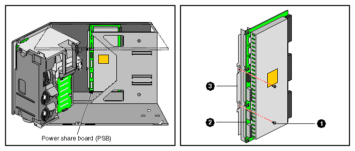
The components shown in Figure 1-14 are:
Screws that attach the bracket to the chassis
Existing PSB
Bracket
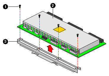
The components shown in Figure 1-15 are:
Screws that attach the existing board to the bracket
Existing PSB
Bracket
To correctly position the new board inside the chassis:
Insert the NON-BRACKET END, then push the other end down so that the two slots in the bracket slide over the corresponding tabs on the chassis wall. Figure 1-16 shows an example.
Use the two screws you removed earlier to attach the bracket to the chassis.
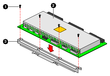
The components shown in Figure 1-16 are:
Screws that attach the new board to the bracket
New PSB
Bracket
To reinstall the board and bracket assembly in the chassis:
Connect the cables to the new PSB.
Reattach the electronics bay.
Connect the new PSB cables to the baseboard.
Reconnect the memory module.
Reinstall the front and rear foam covers.
Reinstall the access cover using the original screws.
Reinstall the power supplies.
Connect all AC power and peripheral device cables to the rear of the system.
Run the FRUSDR load utility to properly configure the upgraded system.
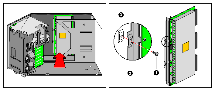
Components shown in Figure 1-17 are:
Two screws that attach the bracket to the chassis
Two slots in the bracket that fit over two tabs on the chassis wall
Two tabs on the chassis wall that force correct alignment of the board and bracket assembly