This chapter provides instructions for installing and removing the texture memory option board on the graphics board installed in the OCTANE workstation.
Two graphics board and texture memory option board configurations are possible in the OCTANE workstation. A single texture memory option board attaches to the OCTANE/SI or SE graphics board, and two texture memory option boards attach to the OCTANE/SSI or SSE graphics board.
The following topics are covered in this chapter:
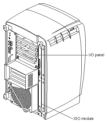
The texture memory option boards attach to graphics boards located on the XIO module in the OCTANE workstation.
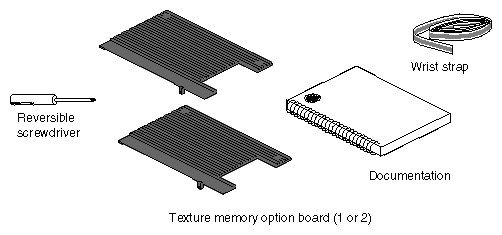
It is always a good idea to check your shipment.You received either one texture memory option board, if you have an SI or SE graphics board, or two texture memory option boards if you have an SSI or SSE graphics board.
To install or remove texture memory option boards, follow the directions in this chapter to complete your task.
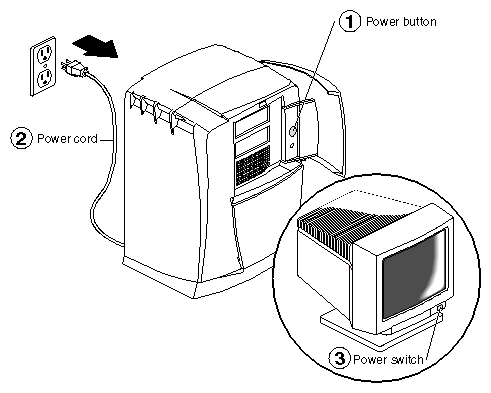
Open the cover and push the power button to power off the OCTANE workstation.
Unplug the power cord.
Power off the monitor by pressing the power switch.
Wait 5 minutes before removing the XIO module.

Warning: The heat sinks on the XIO boards become very hot. Wait 5 minutes after powering off the OCTANE workstation before you remove the XIO module. Test before touching any of the XIO boards.
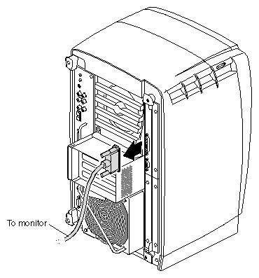
Remove all the cables from the XIO module (only one is shown here).
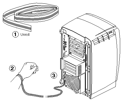
 | Caution: The components inside the OCTANE workstation are extremely sensitive to static electricity; you must wear the wrist strap while replacing parts inside the workstation. |
To attach the wrist strap, follow these steps:
Unwrap the first two folds of the band and wrap the exposed adhesive side firmly around your wrist.
Unroll the rest of the band and peel the liner from the copper foil at the opposite end.
Attach the copper foil to the XIO module. Otherwise, use any convenient and exposed electrical ground, such as a metal part of the OCTANE workstation.
Before removing the XIO module, you must power off the OCTANE workstation, wait
5 minutes, and attach the wriststrap. If you have not already done this, go to “Preparing the Workstation to Install or Remove Texture Memory Option Boards” and follow the instructions through attaching the wriststrap. Then return here and follow the directions beginning with step 1 on page 10.
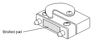
| Caution: Before you remove the XIO module, be aware the compression connectors are on graphics and option boards. The connectors are on the side opposite the handles. Do not grab the back of the XIO module when you remove it, or the compression connectors may be damaged. |
Appendix B, “Care and Cleaning of the Compression Connector,” provides information about the compression connector.
| Warning: The heat sinks on the XIO boards become very hot. Wait 5 minutes after powering off the OCTANE workstation before you remove the XIO module. Test before touching any of the XIO boards. |
Loosen the two captive screws in the XIO module handles with the supplied Phillips screwdriver until the screws are disconnected from the chassis.
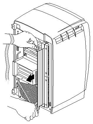
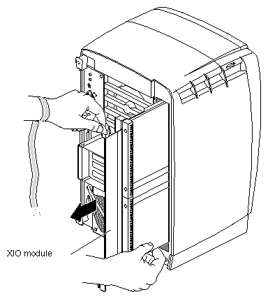
Grasp the handles and pull until the XIO module protrudes about an inch from the chassis.
The handles and XIO module move out about one inch before the I/O panels move.
Pull gently on the handles until the XIO module is about three or four inches out of the workstation.
Grasp the XIO module along its length, and support the base of the module as you remove it from the chassis.
The handle area protrudes when the XIO module is out of the chassis. When the handle is in this position, the identification slots for the XIO boards D and A (shown) and B and C are visible. See Figure 2-10.

Note: Do not push on the handle area after you have removed the XIO module. The XIO module locks to the workstation only if the handle area is protruding. Place the XIO module on a flat, antistatic surface. An empty antistatic bag on your desk works well. Because slots B and C are on the reverse side of the XIO module from slots A and D, choose the slot in which you will place the XIO standalone board. Then turn the XIO module so that slot faces you.
Note: Protective compression connector caps come with the OCTANE workstation. The cap is placed on any compression connector as soon as the XIO module is removed from the chassis, and then removed before placing the XIO module back in the chassis.
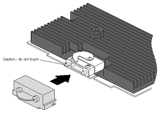
Place a cap on the XIO graphics board compression connector. Spare caps come with the OCTANE workstation. See Figure 2-10.
Caution: Do not touch or bump the gold (front) surface of the XIO compression connector. Touching it could damage the connector. Place a protective cap on XIO compression connector to prevent damage when the XIO boards are removed from the OCTANE workstation. See Appendix B, “Care and Cleaning of the Compression Connector.”
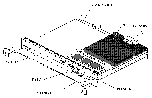
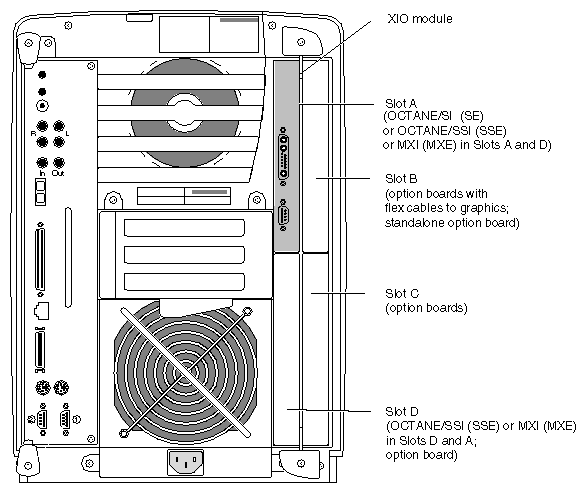
The XIO module is the holding mechanism for XIO graphics or XIO option boards and hold up to four boards. It can be thought of as a tray to which boards are attached. The four quadrants of the XIO module are slots A, B, C, and D. Slots D and A are on one side, slots B and C on the other. A graphics board, option board, or blank panel attaches to each slot on the XIO module. The only exception is the OCTANE/SSI (or SSE) or OCTANE/MXI (or MXE) graphics boards, which occupy the space of slots A and D; they use one XIO connector attaching from the slot A position.
The XIO graphics board must be placed toward the top right of the workstation or it may overheat and be damaged.
The graphics board must be in slot A or slots A and D.
Graphics and option boards may be linked by flex cables.
Caps for the compression connectors are part of the workstation shipment.
Before installing a texture memory option board you must power off the OCTANE workstation, wait 5 minutes for the heat sinks to cool, attach a wriststrap, and remove the XIO module. If you have not already done so, see “Preparing the Workstation to Install or Remove Texture Memory Option Boards” and follow the instructions through removing the XIO module. Be sure to also read “About the XIO Module and XIO Boards” before beginning your task.
| Warning: The heat sinks on the XIO boards become very hot. Wait 5 minutes after powering off the OCTANE workstation before you remove the XIO module. Test before touching any of the XIO boards. |
Graphics boards may be in one slot (A) or two (D and A). Figure 2-12 shows the OCTANE/SI (or SE) graphics board in Slot A. The OCTANE/SSI (or SSE) graphics board uses slots A and D.
Before installing a texture memory option board you must power off the OCTANE workstation, wait 5 minutes for the heat sinks to cool, attach a wriststrap, and remove the XIO module. If you have not already done so, see “Preparing the Workstation to Install or Remove Texture Memory Option Boards” and follow the instructions through removing the XIO module. Be sure to also read “About the XIO Module and XIO Boards” before beginning your task.
Use the same process to install texture memory option boards on the OCTANE/SI (or SE) and OCTANE/SSI (or SSE) graphics boards.
A single texture memory option board installs on the OCTANE/SI (or SE) graphics board. See Figure 2-13.
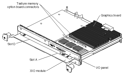
Locate the texture memory option board connectors on the OCTANE/SI (or SE) or OCTANE/SSI (or SSE) graphics board.
See Figure 2-14 for the location of the connectors on the OCTANE/SSI (or SSE) graphics board.
Figure 2-14. Locating the Connectors for the Texture Memory Option Board on the OCTANE/SSI (or SSE) Graphics Board
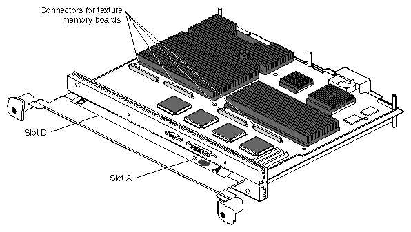
Two texture memory option boards install, side by side, on the OCTANE/SSI (or SSE) graphics board. See Figure 2-14.
If you are installing two texture memory option boards on the OCTANE/SSI (or SSE) graphics board, begin with the set of connectors near the D slot designation, as shown in Figure 2-14.
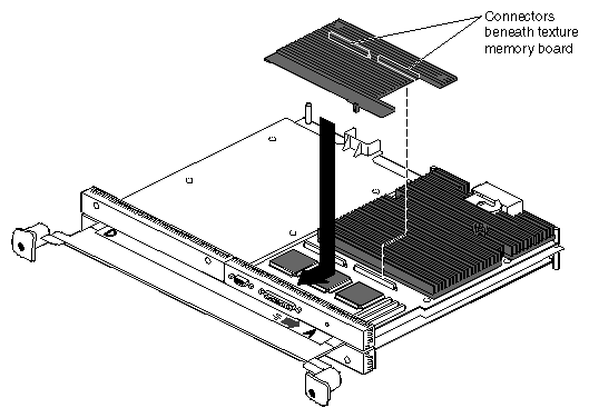
Align the texture memory option board above the graphics board as shown in Figure 2-15.
Lower the texture memory option board and slide the front edge under the I/O panel.
Align the two long connectors on the underside of the texture memory option board with the two connectors on the graphics board.
Press on the top of the texture memory option board above the connectors to seat the connectors.
Note: These connectors must be fully seated for the texture memory board to be recognized.
Place and tighten the nylon screw that came with the texture memory board through the hole in the I/O panel and into the hole on the texture memory option board as shown in Figure 2-16.
Caution: Do not use a metal screw; your board will not perform properly. Order another nylon screw from your authorized service provider if this screw is lost or damaged.
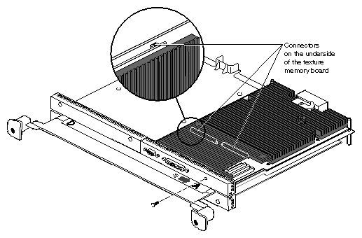
If you are installing texture memory boards on the OCTANE/SSI (or SSE) board, repeat the above steps to install the second board. (After the texture memory boards are installed, the OCTANE/SSI [or SSE] graphics board is known as the OCTANE/MXI [or MXE] graphics board.)
You are finished installing the texture memory option board and are ready to install the XIO module. Go to “Replacing the XIO Module”.
Before removing a texture memory option board you must power off the OCTANE workstation, wait 5 minutes for the heat sinks to cool, attach a wrist strap, and remove the XIO module. If you have not already done so, see “Preparing the Workstation to Install or Remove Texture Memory Option Boards” and follow the instructions through removing the XIO module. Be sure to also read “About the XIO Module and XIO Boards” before beginning your task.
Use the same process to remove texture memory option boards on the OCTANE/SI (or SE) and OCTANE/MXI (or MXE) graphics boards.
A single texture memory option board is installed on the OCTANE/SI (or SE) graphics board. Two texture memory option boards are installed on the OCTANE/MXI (or MXE) graphics board.
If you are removing texture memory option boards from the OCTANE/MXI (or MXE) graphics board, begin with the texture memory option board closest to slot A.
Remove the nylon screw from the I/O panel.
Push up on the ends of the texture memory option board farthest from the I/O panel to release the two connectors beneath.
Lift up and back to remove the texture memory option board from beneath the edge of the I/O panel.
Caution: If you are removing texture memory option boards from the OCTANE/MXI graphics board, be sure to remove both texture memory option boards. Follow the instructions in this section. Both texture memory boards must be removed for the OCTANE/MXI graphics board to work properly. If you are finished removing texture memory option boards, go to the next section, “Replacing the XIO Module.”.
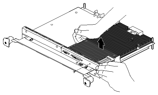
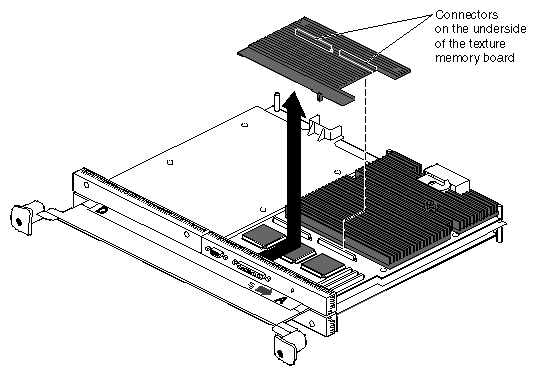
Figure 2-20. Installing the Slots A and D on the XIO Module Toward the Interior of the OCTANE Workstation
Follow these instructions to install the XIO module:
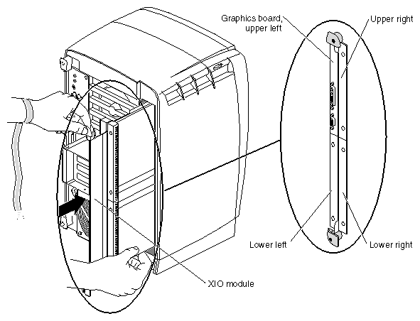
Slide the XIO module into guides on the top and bottom of the workstation with the graphics board to the upper left.
Before you insert the XIO module, make sure the handle portion protrudes in a locked position from the I/O panels, as shown in Figure 2-21.
If the handles are flush with the I/O panels, the XIO module stops during insertion. Pull out the handles until the handle portion of the XIO module looks like Figure 2-21.
Grasp the handle area while supporting the XIO module, and slide the module into to the chassis.
Use the handles to push the XIO module into a locked position. (The I/O panels are nearly flush with the workstation when properly inserted, however, there is a slight variation in the depth of the boards.)
Tighten the captive screws in the handles so that the XIO module is attached to the OCTANE workstation.
Remove the wrist strap.
Reconnect all cables to the XIO module.
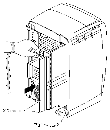
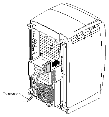
You have finished replacing the XIO module.
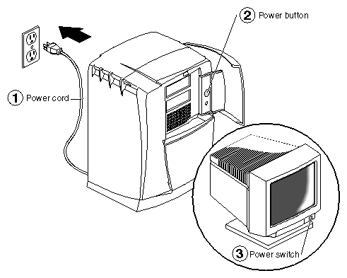
Before powering on, read the next section for instructions on verifying the installation. The verification process begins during the power on sequence. During the power on sequence, at the Starting Up the System notifier, click the Stop for Maintenance button, then follow the instructions in the next section, “Verifying Texture Memory Board Installation”.
Plug the power cord into an electrical outlet.
Push the power button on the front of the OCTANE workstation.
Push the power switch on your monitor.
To determine if your texture memory board is properly installed, verify the installation by accessing the System Maintenance Menu.
During power on, at the Starting Up the System notifier, click the Stop for Maintenance button, or press Esc to bring up the System Maintenance Menu.
Choose option 5, Enter Command Monitor.
At the prompt, type hinv.
Look for a line that begins with Graphics. Depending on the version of the graphics board, you see one of the following:
SI or ESI
SI with texture option or ESI with texture option
SSI or ESSI
MXI or EMXI
Note: MXI (or MXE) is an SSI (or SSE) with two texture memory boards installed. If either SI (or SE) with texture option or MXI (or MXE) is reported, the texture memory option board is properly installed and recognized by the OCTANE workstation. No additional information is provided if two texture memory option boards are installed.
If you do not see SI (or SE) with texture option or MXI (or MXE), power off the OCTANE workstation and repeat the installation process. Follow the instructions in this guide. Press firmly above the texture memory board connectors to ensure they are properly seated.
If the texture memory option board is still not recognized when accessing hinv, call your authorized service representative.
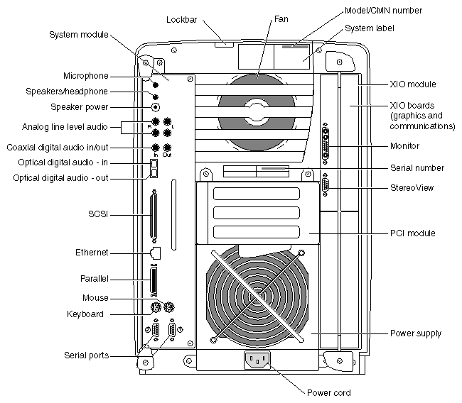
If you received a system upgrade label, place it on the system label.
Face the back of the OCTANE workstation. The system label (containing the model/CMN number) is located at the top center of the back of the workstation.
Place the label over the VCCI and SISPR 22 information.