This chapter describes the geometry data type and how it is used in the Explorer environment. It defines the geometry data type and explains how geometry is created in Explorer. It also describes the interface between Explorer and IRIS Inventor™, a 3-D graphics development tool, and explains the role of the Inventor scene graph in creating more complex geometry.
The API (Application Programming Interface) routines are listed, and examples of user function code for writing modules that produce or manipulate geometry are included.
The cxGeometry data type is a root data type, which means it can be specified as a data type on a port and will pass data between modules. It enables Explorer to handle geometry objects by providing a container for IRIS Inventor scene graph specifications. Inventor is an object-oriented graphics library of objects and methods used to create interactive 3-D graphics. The Explorer Render module and other geometry modules draw on Inventor technology. The geometry objects that Explorer uses to visualize numerical data are created by connecting nodes to form an Inventor scene graph. The scene graph constitutes the Explorer geometry object.
Explorer allows you to manipulate Inventor nodes to form geometry objects through the geometry subroutines in the API. You can output most of the geometry you need in Explorer by using the Geometry Library, which calls Inventor routines, in this way. To create geometry in Explorer, you need not have Inventor installed on your system.
To build a module that reads geometry, that is, that accepts the cxGeometry data type on its input port, you need direct access to Inventor and its libraries. You also need Inventor if you want to obtain more complex rendering effects than Explorer can provide. To write a scene graph with direct reference to the Inventor library, you must have Inventor installed on your system.
You can use Inventor with C and C++, but not with Fortran. If you are programming in Fortran, you must use the Explorer subroutines for all your geometry needs.
This chapter points you toward Inventor for creating complex graphical effects that are outside the scope of Explorer, but it does not tell you how to use Inventor. For more information, refer to the IRIS Inventor Programming Guide. To obtain IRIS Inventor, see your Silicon Graphics sales representative.
The cxGeometry data type is a simple data structure that transcribes an Inventor scene graph into a linear data stream called the delta protocol, encoded in an Inventor binary file format. It is opaque to Explorer users. The scene graph can then be moved between modules that are capable of processing it. A scene graph is a hierarchical geometrical construction made of nodes that contain specific details about the scene graph, or geometry object. “Scene graph” is the Inventor term, and “geometry object” is the Explorer term for visualized data.
The delta protocol is so called because its primary function is to convey information about changes in the composition of the original scene graph. These changes occur when you fire a module that renders, colors, stretches, reads, or writes geometry. For example, you may use a widget on an upstream module that processes geometry to alter the shape or orientation of an object in the Render module. Other Explorer modules that process geometry are ReadGeom, WriteGeom, LatToGeom, PyrToGeom, and VolumeToGeom.
The data type definition is:
closed shared root typedef struct {
    short    id;
    long     count; */ length of the data stream in bytes */
    char     data[count];  /* the delta protocol */
} cxGeometry;
|
Figure 5-1 shows the structure of the cxGeometry data type.

If you plan to use only the simple Explorer API to create geometry, you do not need to understand how Inventor represents scenes, and you can skip to “Data Type Declaration.” However, a rudimentary knowledge of how Inventor works may help you understand geometry is manipulated in Explorer.
A scene graph is the Inventor term for a hierarchical, 3-D description of scene data. It consists of an ordered collection of nodes, each of which defines a specific shape (or geometry), property, or grouping aspect of the scene. The hierarchy is created by adding sublevels of nodes to the top-level or root node in a scene graph, creating a directed acyclic graph. Figure 5-2 shows a simple scene graph. The heavy line running from the root node down the right-hand branch to the shape node shows the hierarchical path or progression in the graph.
The node[5] is the basic building block for creating scene graphs in Inventor. Each node holds a piece of information, such as a shape description, a geometric transformation, a camera position, or a light source. Each scene graph has a root node, which is the first node you create. You can apply actions to a scene graph, such as rendering, picking, and writing to a file. The Explorer Render module renders numerical data in the form of a scene graph.
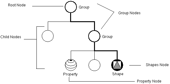
Nodes fall into three categories: shape nodes, which represent 3-D geometric objects; property nodes, which represent qualitative values, such as appearance; and group nodes, which collect single nodes into graphs.
Each node has a set of fields that describe the parameters of the node. For example, a node defining a point light source has three fields, intensity, color, and location. Each of these fields can be given a value (location) or range of values (intensity). The order in which nodes are arranged is important because it determines how the values that each node contains are acted upon.
When a module with a geometry input is initialized or fired for the first time, it creates a root node and an Inventor receiver object, which act as a pair to deal with incoming data from a specific upstream module. The root node and receiver object together translate the data from this module and create a scene graph from it. Each upstream module has its own root node and receiver object in the receiving module. This prevents data updates from one module being passed to nodes that contain data from another module. The root node/receiver object pairs control the distribution of new data to the correct nodes.
Data is moved between modules in the form of a delta protocol. Before the geometry can be passed out of a module and sent downstream, the scene graph nodal structure must be transcribed back into the delta protocol and wrapped as an Explorer Geometry data type. This is done by the root node and an Inventor sender object of the class SoTranSender.
The Explorer API routine cxGeoSender is a sender object that writes the delta protocol, and cxGeoReceiver is a receiver object that reads the protocol. You can use the API routine cxGeoInventorDefine to transcribe a complete scene graph, including the root node and all the nodes beneath it. You can also define only one or two nodes that carry new values for a particular part of the downstream scene graph. See the example of how to change the value of a color node in “Stepping Through the Code”.
For detailed information on using Inventor to create and manipulate nodes and scene graphs, refer to the IRIS Inventor Programming Guide.
Figure 5-3 shows the node relationships in a scene graph.

Every Explorer module with a geometry input port can accept scene graph data wrapped in the geometry data type. The receiving module must have in its user function a set of routines that can turn the incoming geometry protocol into a complete scene graph. A module can also accept updates to a particular area of a scene graph already received.
For example, if you change the value of a widget on a geometry-producing module upstream from the Render module after you have fired the upstream module at least once, you need send only the changed widget value to the Render module, not the complete geometry structure. The Render module interprets the changed data and applies it to the correct portion of the scene graph it currently contains.
To write a module that accepts and reads geometry on its input port, you must use Inventor. You need the Inventor functions for manipulating and changing scene graph components. You can, however, write a module that accepts other data types and outputs geometry using only the Explorer API routines. These routines let you create geometry shapes and provide a few basic editing functions, such as changing the color of a geometry object, but they do not let you interpret an incoming delta protocol.
The Explorer API routines are listed in alphabetical order in the IRIS Explorer Reference Pages.
To illustrate how Explorer and Inventor code interact in a geometry module, here is a simple color modification module, which will modify the color nodes of any geometry that passes through it. It has a geometry input port, capable of accepting multiple inputs, and a geometry output port. It also has three floating point parameters (RGB) for the color value.
The module operates by reading a geometry object, turning it into Inventor code, manipulating the object, then producing geometry. The user function for the module resides in /usr/explorer/src/MWGcode/Geometry/C++/ColorMod.C. It does not exist in Fortran, because Inventor has no Fortran API.
The originating module can color the geometry it sends downstream to the Render module. If the geometry has no color, Render gives it default colors. Here is code for a module that changes the color in geometry that has an already defined color. More specifically, it:
Converts the incoming delta protocol into geometry using cxGeoReceive. It can receive geometry from multiple upstream modules.
Attaches a color node to the root node at the top of the geometry tree. This color node is given the values of the three RGB parameters.
Searches the rest of the tree (in particular, the material nodes) and deactivates any other color nodes it finds.
Outputs the results, namely a new color for the geometry in the Render module.
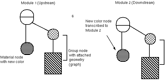
Figure 5-4 through Figure 5-6 show the sequence of events in the process.
#include <cx/DataAccess.h> #include <cx/DataTypes.h> #include <cx/Geometry.h> #include <cx/PortAccess.h> |
Every module makes reference to header files that contain data structures important to the functioning of the module. In addition to the Explorer cx/*.h header files, this module includes six Inventor header files that define the Inventor objects required to create the geometry.
#include <Inventor/SoTranscribe.h>
#include <Inventor/nodes/SoBaseColor.h>
#include <Inventor/nodes/SoGroup.h>
#include <Inventor/nodes/SoMaterial.h>
#include <Inventor/nodes/SoSeparator.h>
#include <Inventor/actions/SoSearchAction.h>
typedef struct GeoLink {
 long wireId;
 SoGroup *root;
 SoTranReceiver *receiver;
 struct GeoLink *next;
} GeoLink;

GeoLink *geoList = NULL; /* head of linked list of inputs */

SoGroup *rootNode; /* root node of all geometry */

extern “C” void color(
 cxGeometry *input, /* input geometry */
 int flag, /* true if geometry is new */
 float red,
 float grn,
 float blu,
 cxGeometry **output)
{
   int i; /* loop variable */
/* do first time initialization */
static int first = 1;
if ( first )
 {
     first = 0;

     /* initialize the geometry library */
     cxGeoInit();

     /* create the root node */
     rootNode = new SoSeparator();
     rootNode->ref();
|
Create the root and color nodes
     /* create the color node */
     SoBaseColor *baseColor = new SoBaseColor();
     rootNode->addChild(baseColor);
 }
     /* create the output geometry */
     output = cxGeoNew();
     cxGeoBufferSelect(*output);

     /* remove the previous color node (if it exists) */
     cxGeoSender->remove(NULL,0);
    /* update the color of the color node */
    (SoBaseColor *)rootNode->getChild(0))
    ->rgb.setValue(red,grn,blu);

    /* send the updated color node */
    cxGeoSender->insert(rootNode->getChild(0),NULL,0);
|

The module must check to see if the geometry arriving on the input port is new or old. If it is new, it has no wireID. The module then proceeds to create a new root node and material node containing the base color.
 if ( flag ) /* new geometry has arrived */
 {
     /* get the wire id */
     long id =
     cxInputDataConnIDGet(cxInputPortOpen(“Input”));

     /* check against previously received ids */
     GeoLink *current;
     for ( current = geoList; current;
     current = current->next )
     {
               if ( current->wireId == id )
                   break;
      }

  /* if this is a new wire, create an entry */
  if ( current == NULL )
{
       /* add a new link to the list */
       current = new GeoLink;
       current->next = geoList;
       geoList = current;

     current->wireId = id;
     current->root = new SoGroup();
     rootNode->addChild(current->root);
     current->receiver =
     new SoTranReceiver(current->root);
 }
 else  /* remove this node downstream */
       cxGeoSender->remove(NULL,
       rootNode->findChild(current->root));

 /* transcribe the geometry in */
 cxGeoReceive(input,current->receiver);
|

/* OPERATE ON GEOMETRY HERE */

           /* find all material nodes */
           SoSearchAction materialSearch;
           materialSearch.setType(SoMaterial::getClassTypeId())
           materialSearch.setFindAll(TRUE);
           materialSearch.apply(current->root);

           /* loop over paths */
            SoPathList materialPaths = materialSearch.getPaths();
            for ( i = 0; i < materialPaths.length(); i++ )
            {
                 SoPath *p = materialPaths[i];
                 SoMaterial *m =
                 (SoMaterial *)p->getNodeFromTail(0);

                 /* ignore the diffuse color */
                 m->diffuseColor.setIgnored(TRUE);
            }

             /* find all base color nodes */
             SoSearchAction colorSearch;
             colorSearch.setType(SoBaseColor::getClassTypeId());
             colorSearch.setFindAll(TRUE);
              colorSearch.apply(current->root);

             /* loop over paths */
            SoPathList colorPaths = colorSearch.getPaths();
            for ( i = 0; i < colorPaths.length(); i++ )
            {
                SoPath *p = colorPaths[i];
                SoBaseColor *c =
               (SoBaseColor *)p->getNodeFromTail(0);
                SoGroup *g = (SoGroup*)p->getNodeFromTail(1);


                /* remove the base color node */
                g->removeChild(c);
             }
 END GEOMETRY OPERATIONS */
        /* send out the new geometry */
        cxGeoSender->insert(current->root,NULL,
             rootNode->findChild(current->root));
  }

  /* close the geometry */
 cxGeoBufferClose(*output);
}
|
The cxGeometry data type, though defined in the Explorer typing language, can be considered as a C structure. Fortran users need to set pointers to the data type structures when they use them. The type declaration resides in the header file /usr/explorer/include/cx/cxGeometry.h.
The cxGeometry data type structure is defined as follows:
typedef struct cxGeometry {
    cxDataCtlr       ctlr;
    short             id;
    long              count;
    unsigned char    *data;
} cxGeometry;
|
The cxGeometry data type has its own API subroutine library that enables you to write simple Explorer modules that output scene graphs without manipulating Inventor code. You can create and manipulate the geometry objects by using the geometry subroutines listed below. To create more complex modules, you can use Inventor directly.
The geometry subroutines are described in the IRIS Explorer Reference Pages. Table 5-1 lists the subroutines and briefly defines each one.
Table 5-1. Geometry Subroutines
Subroutine | Purpose |
|---|---|
cxGeoNew | Creates a new Explorer geometry data structure |
cxGeoInit | Initializes the Explorer Geometry Library |
cxGeoPointsDefine | Creates a set of points |
cxGeoLinesDefine | Creates a set of unclosed polylines |
cxGeoPolysDefine | Creates a set of polygons |
cxGeoTrisDefine | Creates a set of triangle meshes |
cxGeoSpheresDefine | Creates a set of spheres |
cxGeoGridDefine | Creates a grid geometry object |
cxGeoTextDefine | Creates a text object |
cxGeoOctreeDefine | Creates a volume object rendered as an octree |
cxGeoInventorDefine | Creates an entire Inventor scene graph |
cxGeoNormalAdd | Adds normals to the current geometry object |
cxGeoColorAdd | Adds colors to the current geometry object |
cxGeoABGRAdd | Adds packed (32-bit) colors to the current geometry object |
cxGeoComplexityAdd | Specifies the level of rendering detail |
cxGeoTransparencyAdd | Add transparency to the current geometry object |
cxGeoXformPop | Makes the current object the parent of the current transform group |
cxGeoXformPush | Groups objects under a parent hierarchy object |
cxGeoIdentity | Resets the transform on the current object |
cxGeoTranslate | Translates the current geometry object |
cxGeoRotate | Rotates the current geometry object |
cxGeoScale | Scales the current geometry object |
cxGeoMatrixCat | Applies an arbitrary 4x4 transform to the object |
cxGeoReceive | Receives Explorer input data for transcription |
cxGeoFocus | Specifies the current object or transform for editing |
cxGeoRoot | Makes the root object the current object |
cxGeoDelete | Makes the root object the current object |
cxGeoBufferClose | Prepares a geometry buffer to be sent |
cxGeoBufferSelect | Specifies a geometry buffer for subsequent scene edits |
The examples that follow show the use of both Explorer subroutines and Inventor classes to create and manipulate geometry in modules. The code examples are located in the /usr/explorer/src/MWGcode/Geometry/* subdirectories.
This example creates some line segments, using Explorer subroutines and outputs them as geometry. C++ and Fortran versions are given, and the code is in /usr/explorer/src/MWGcode/Geometry/C++/LineSegment.C and /usr/explorer/src/MWGcode/Geometry/Fortran/LineSegment.f.
#include <cx/DataTypes.h>
#include <cx/DataAccess.h>
#include <cx/Geometry.h>

static float p[] = {
       0.0, 0.0, 0.0,
       1.0, 0.0, 0.0,
       1.0, 1.0, 0.0,
       0.0, 1.0, 0.0,
       0.0, 1.0, 1.0,
       1.0, 1.0, 1.0,
       1.0, 0.0, 1.0,
       0.0, 0.0, 1.0
};

extern “C” void line(cxGeometry **geom)
{
     /* initialize geometry library */
     static int flag = 1;
     if ( flag )

         flag = 0;
         cxGeoInit();
      }

       /* open buffer */
      geom = cxGeoNew();
     cxGeoBufferSelect(*geom);

     cxGeoRoot();
     cxGeoDelete();

     cxGeoLinesDefine(8,p,0,NULL);

     cxGeoBufferClose(*geom);
}
|
subroutine linef ( h_geom )

 integer h_geom

C
C Please complete the user function by adding subprogram lines
C here.
C

#include <cx/DataAccess.inc>
#include <cx/Geometry.inc>
 integer flag
 real p(24)

 data flag/1/
data p/0.0, 0.0, 0.0,
      + 1.0, 0.0, 0.0,
      + 1.0, 1.0, 0.0,
      + 0.0, 1.0, 0.0,
      + 0.0, 1.0, 1.0,
      + 1.0, 1.0, 1.0,
      + 1.0, 0.0, 1.0,
      + 0.0, 0.0, 1.0/

     if ( flag .eq. 1 ) then
        flag = 0
        call cxGeoInit
        endif

        h_geom = cxGeoNew()
        call cxGeoBufferSelect(H_GEOM)

          call cxGeoRoot
          call cxGeoDelete

          call cxGeoLinesDefine(8,p,0,0)

          call cxGeoBufferClose(h_geom)

          return
          end
|
Here are two examples of a user function showing how you can use the IRIS Inventor library to create geometry objects. Neither example has a Fortran equivalent because Inventor has no Fortran API.
This is a simple example of how to use the Inventor library, written in C++. The function wraps an image onto a sphere. The code is in /usr/explorer/src/MWGcode/Geometry/C++/Texture.C
#include <cx/DataAccess.h>
#include <cx/DataTypes.h>
#include <cx/Geometry.h>
#include <cx/cxParameter.api.h>
#include <cx/cxGeometry.api.h>
#include <Inventor/SoTranscribe.h>
#include <Inventor/nodes/SoSphere.h>
#include <Inventor/nodes/SoTexture2.h>
#include <Inventor/nodes/SoSeparator.h>
#include <Inventor/nodes/SoMaterial.h>

extern “C” {
  void  makeSphere  (
         float            radius,
         char            *texfile,
         cxGeometry *   * geo )
{
  static int first = 1;
  SoGroup *rootNode;

  if ( first )
  {
    first = 0;
    cxGeoInit();
  }
  rootNode = new SoSeparator();
  rootNode->ref();
  *geo = cxGeoNew();
  cxGeoBufferSelect(*geo);
  cxGeoRoot();
  cxGeoDelete();
  SoSphere *sph = new SoSphere();
  SoTexture2 *tex = new SoTexture2();
  SoMaterial *m = new SoMaterial();
  m->diffuseColor.setValue(1.0,1.0,1.0);
  tex->filename.setValue(texfile);
  sph->radius = radius;
  rootNode->addChild(tex);
  rootNode->addChild(m);
  rootNode->addChild(sph);
  cxGeoInventorDefine(rootNode);
  rootNode->unref();
  cxGeoBufferClose(*geo);
}
}
|
This is a reasonably small module, written in C++, that implements a geometry renderer using the IRIS Inventor library. The code is in /usr/explorer/src/MWGcode/Geometry/C++/SimpleRender.C
For simplicity, several limitations have been accepted:
The rendering window does not downsize very gracefully. The real renderer turns off decoration when the window goes below a certain size .
Only one geometry input is supported. This module can have fatal namespace collisions with fanned-in inputs, though in practice it will usually work. The proper way to handle multiple geometry streams is to use a different receiver object for each one .
The viewer in this module is very simple and does not support any editing or picking facilities.
#include <X11/Intrinsic.h>
#include <Inventor/SoTranscribe.h>
#include <Inventor/SoXt.h>
#include <Inventor/nodes/SoDirectionalLight.h>
#include <Inventor/nodes/SoGroup.h>
#include <Inventor/nodes/SoLightModel.h>
#include <Inventor/nodes/SoSeparator.h>
#include <Inventor/nodes/SoShapeHints.h>
#include <Inventor/viewers/SoXtExaminerViewer.h>
#include <cx/DataAccess.h>
#include <cx/DataTypes.h>
#include <cx/Geometry.h>
#include <cx/PortAccess.h>
#include <cx/UserFuncs.h>
#include <cx/XtArea.h>

Widget top;  /* top level widget for drawing area */
SoGroup *group;                            /* root for incoming geometry */
SoTranReceiver *receiver;   /* receiver object for incoming geometry */
SoXtViewer *viewer;    /* Inventor viewer */

extern "C" void renderlite(
    cxGeometry *geo,    /* incoming geometry */
    int geoFlag,        /* nonzero if geometry is new */
    long window,        /* window id of drawing area */
    int windowFlag)     /* nonzero if window is new */
{
  static int first = 1;/* initialization flag */
  if ( first && window )
  {
     /* reset initialization flag */
     first = 0;

    /* initialize Xt and Inventor */
    top = cxXtAreaInitialize();
    SoXt::init(top);

    /* create the environment */
    SoGroup *root = new SoSeparator();
    root->ref();

    /* shape hints */
    SoShapeHints *n1 = new SoShapeHints();
    n1->hints.setValue(SoShapeHints::ORDERED);
    root->addChild(n1);

    /* create the node for the incoming geometry */
    group = new SoGroup();
    root->addChild(group);

    /* create the receiver object */
    receiver = new SoTranReceiver(group);


    /* create the viewer */
    viewer = new SoXtExaminerViewer();
    viewer->setSceneGraph(root);
    viewer->setSize(SbVec2s(100,100));
    viewer->build(top,"SoXtComponentShell");
    viewer->show();

     /* attach the viewer widget to the Explorer Form widget */
    Widget vw = viewer->getWidget();
    XtVaSetValues(vw,
      XmNtopAttachment,XmATTACH_FORM,
      XmNbottomAttachment,XmATTACH_FORM,
      XmNrightAttachment,XmATTACH_FORM,
      XmNleftAttachment,XmATTACH_FORM,
      NULL);

    /* attach widget to window */
    cxXtAreaAttach(top,window);
}

if ( windowFlag )/* window has changed state or size */
   cxXtAreaResize(top,window);

if ( geoFlag )/* new geometry has arrived */
  {
    cxGeoReceive(geo,receiver);
    viewer->viewAll();
  {
}
}
The following example creates textured spheres. The code is in /usr/explorer/src/MWGcode/Geometry/C/PolySegment.c and /usr/explorer/src/MWGcode/Geometry/Fortran/PolySegment.f.
#include <cx/DataTypes.h>
#include <cx/DataAccess.h>
#include <cx/UserFuncs.h>
#include <cx/Geometry.h>
#include <cx/Lookup.h>

float lins[] = {0.,0.,0., 0.,0.,1., 0.,1.,1., 0.,1.,0.,
        1.,0.,0., 1.,0.,1., 1.,1.,1., 1.,1.,0. };

int conn[] = {0,1,2,3,0,4,5,6,7,4,-1,1,5,-1,2,6,-1,3,7,-1};
int conn2[] = {0,1,5,4,-1,2,3,7,6,-1};

void display()
{
 cxLattice *cmap;
 cxGeometry *geo;
 cxLookup *clut;
 float col[4],sphs[10][3],rads[10],x;
 int i,j;
 cmap =  (cxLattice*)cxInputDataGet(cxInputPortOpen(“colormap”));
 if(cmap == NULL){
   printf(“geometry: no color map present\n”);
   return;
 }

 for(i=0;i<10;i++){
   for(j=0;j<3;j++){
     sphs[i][j] = i;
      }
      rads[i] = i / 10.0;
 }
 clut = cxLookupCreate(cmap,1);
 geo = cxGeoNew();
 if( cxDataAllocErrorGet() ) goto cleanupGeo;
 cxGeoBufferSelect(geo);
 cxGeoRoot();
 if( cxDataAllocErrorGet() ) goto cleanupSelected;
 cxGeoDelete();
 if( cxDataAllocErrorGet() ) goto cleanupSelected;

 cxGeoSpheresDefine(5,sphs[0],rads);
 if( cxDataAllocErrorGet() ) goto cleanupSelected;
 x = 1.;
 cxLookupInterp(clut,&x,(void *)col);
 cxGeoColorAdd(1,col,CX_GEO_PER_OBJECT);
 if( cxDataAllocErrorGet() ) goto cleanupSelected;

 cxGeoLinesDefine(8,lins,20,conn);
 if( cxDataAllocErrorGet() ) goto cleanupSelected;
 x = 4.;
 cxLookupInterp(clut,&x,(void *)col);
 cxGeoColorAdd(1,col,CX_GEO_PER_OBJECT);
 if( cxDataAllocErrorGet() ) goto cleanupSelected;
 cxGeoPolysDefine(8,lins,10,conn2);
 if( cxDataAllocErrorGet() ) goto cleanupSelected;
 x = 5.;
 cxLookupInterp(clut,&x,(void *)col);
 cxGeoColorAdd(1,col,CX_GEO_PER_OBJECT);
 if( cxDataAllocErrorGet() ) goto cleanupSelected;

 cxGeoBufferClose(geo);
 cxOutputDataSet(cxOutputPortOpen(“geom”),geo);
 return;

cleanupSelected:
 cxGeoBufferClose(geo);
cleanupGeo:
 cxDataRefDec(geo);
 return;
}

void geom_init()
{
 cxGeoInit();
}

cxFuncTable cx_FuncTable[] = {
     (cxFuncTable)display,
         NULL
};

cxHookTable cx_HookTable[] = {
   cx_func_init, geom_init,
   cx_func_last
};
|
  subroutine display(cmap,geo)
#include “cx/DataAccess.inc”
#include “cx/Lookup.inc”
  integer geo,cmap,clut
  integer CX_GEO_PER_OBJECT
  parameter(CX_GEO_PER_OBJECT = 1)
  logical first
  integer conn(20),conn2(10)
  real sphs(3,10),rads(10),lins(3,8),col(4)
  data lins/0.,0.,0., 0.,0.,1., 0.,1.,1., 0.,1.,0.,1/
     1.,0.,0., 1.,0.,1., 1.,1.,1., 1.,1.,0. /
  data conn/0,1,2,3,0,4,5,6,7,4,-1,1,5,-1,2,6,-1,3,7,-1/
  data conn2/0,1,5,4,-1,2,3,7,6,-1/
  data first/.true./
c
|
 | Note: No hook function initialization. |
  if(first)then
     call cxGeoInit
      first = .false.
   endif
c
c  initial stuff
c
     do i=1,10
      do j=1,3
       sphs(j,i) = i
      end do
      rads(i) = real(i)/10.0
     end do
     geo = cxGeoNew()
     if( cxDataAllocErrorGet() .NE. 0 ) goto 9999
     call cxGeoBufferSelect(geo)
     call cxGeoRoot
     if( cxDataAllocErrorGet() .NE. 0 ) goto 999
     call cxGeoDelete
c
c   spheres
c
    call cxGeoSpheresDefine(5,sphs,rads)
    if( cxDataAllocErrorGet() .NE. 0 ) goto 999
    x = 1
    clut = cxLookupCreate(cmap,1)
    call cxLookupInterp(clut,x,col)
    call cxGeoColorAdd(1,col,CX_GEO_PER_OBJECT)
    if( cxDataAllocErrorGet() .NE. 0 ) goto 999
c
c   lines
c
    call cxGeoLinesDefine(8,lins,20,conn)
    if( cxDataAllocErrorGet() .NE. 0 ) goto 999
    x = 4
    call cxLookupInterp(clut,x,col)
    call cxGeoColorAdd(1,col,CX_GEO_PER_OBJECT)
    if( cxDataAllocErrorGet() .NE. 0 ) goto 999
c
c   polys
c
    call cxGeoPolysDefine(8,lins,10,conn2)
    if( cxDataAllocErrorGet() .NE. 0 ) goto 999
    x = 5
    call cxLookupInterp(clut,x,col)
    call cxGeoColorAdd(1,col,CX_GEO_PER_OBJECT)
    if( cxDataAllocErrorGet() .NE. 0 ) goto 999
c
c   termination stuff
c
    call cxGeoBufferClose(geo)
    return
c
c   memory allocation error cleanup
c
999  continue
     call cxGeoBufferClose(geo)
9999 continue
     call cxDataRefDec(geo)
     return
     end
|
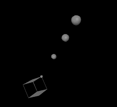
Figure 5-7 shows what the module output looks like.