This chapter describes how to install a system controller PROM upgrade and, if needed, a remote system control (RSC) port in a Silicon Graphics CHALLENGE server.
Deskside-system PROM and RSC port installation is described in Sections 2.1 through 2.6. Rack-system PROM installation is described in Section 2.7.
This upgrade to the system controller PROM (version 3.10) enhances the capabilities of the remote system control port, adding features required for the Oracle Parallel Server.
Some systems may also need the addition of a remote system control port.
Silicon Graphics deskside CHALLENGE systems have been shipped with a number of different remote system control port configurations. Early systems had a plate containing two DB9 ports. On these systems, the top port is the RSC port. Many systems were shipped with a plate that had only one DB9 port, marked "Remote System Control Port, SSE Use Only." Finally, a number of systems were shipped with a blank plate in place of the RSC port. This document describes how to replace one of these blank plates with a remote system control port.
Inspect the system to see if it already has a remote system control port:
Open the drive door to expose the drives and the front-panel retainer latches.
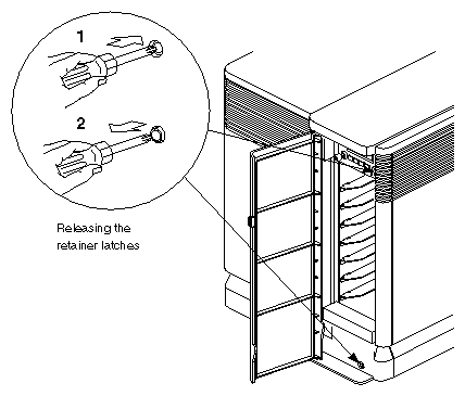
Release the two retainer latches by fully pressing and releasing each latch with a pointed object, such as a screwdriver. See Figure 2-1 for details.
Open the front panel.
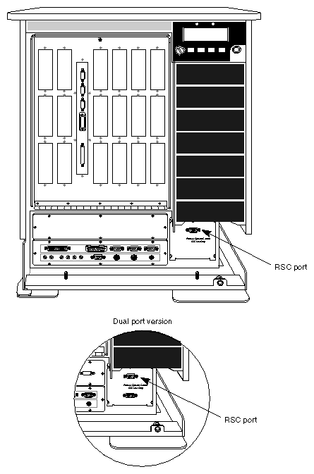
Look below the disk drives to see if the system already has a remote system control port.
If the system has either a single-port plate or a double-port plate (see Figure 2-2), the RSC port installation is done. Proceed to Section 2.5, "Installing the System Controller PROM Upgrade."
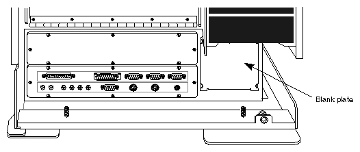
If the system has a blank plate (see Figure 2-3), you need to install the RSC port. Contact CSD Logistics and order SGI Part number 013-0624-001 (RS-232 plate assembly).
Ensure that you have all of the components required for the installation:
Prepare the system for the kit installation as follows:
Ensure that the customer has backed up all data on the system and has verified the saved files.
Make sure that all users are logged off of the system.
Become superuser, and then shut down the system by typing:
shutdown -y g0When the system reaches the PROM monitor state, type
printenvSince the procedures described here may cause some of these values to change, carefully make a record of all the information supplied by printenv.
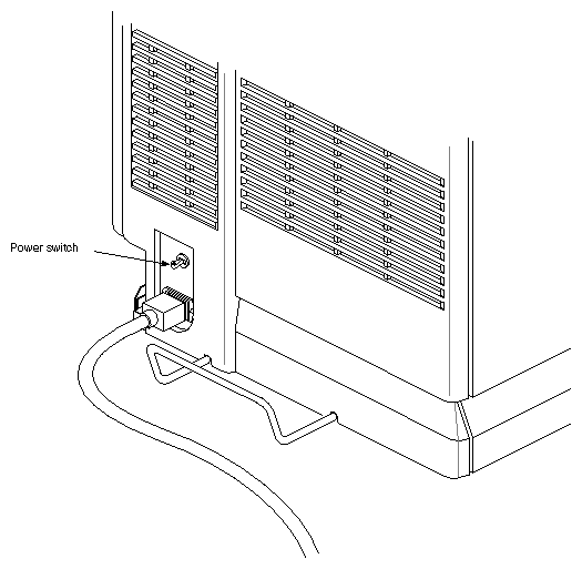
Power off the system. The power switch is located at the rear of the chassis, near the AC power cord receptacle (see Figure 2-4).
Disconnect the system from the power source (unplug the power cable).
 | Warning: It is important that you actually disconnect the power cable. |
If the system did not have a remote system control port (see Section 2.2, "Preliminary Inspection"), install one as described in this section. Otherwise, proceed to Section 2.5, "Installing the System Controller PROM Upgrade."
Remove the existing blank plate as follows:
Using a Phillips screwdriver, remove the screw in the top center of the blank plate (below the disk drives).
Tip the top of the blank plate away from the chassis until it is nearly horizontal.
Gently lift the plate while pulling it away from the chassis so that the locating tabs in the bottom come out of the slots in the chassis.
Set the plate aside. After installing the RSC port, you will have no further need for the blank plate.
Locate the ribbon cable by performing the following steps:
Look into the chassis opening (where the blank plate used to be) and try to find the end of the ribbon cable (see Figure 2-5). It should be close to the opening, but it may have slipped back into the chassis during shipping or subsequent motion.
When you find the end of the ribbon cable, pull it out of the chassis panel opening approximately six inches, being careful not to damage the cable (or your hands) on the sheet-metal edges.
| Warning: You will be reaching close to the 220 Volt AC power input cables. Unless the system is UNPLUGGED, there is a risk of receiving a dangerous electric shock. |
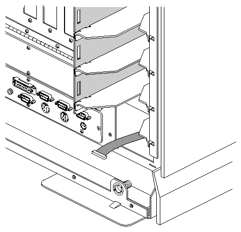
At the front of the system, with the ribbon cable extending from the RSC port chassis opening, perform the following steps:
Plug the end of the ribbon cable into the RSC port assembly. It is keyed to only insert in the correct orientation.
Carefully push the excess length of ribbon cable back into the chassis opening.
Holding the RSC port at a slight angle, insert the bottom locating tabs into the matching slots in the chassis. (see Figure 2-6).
While making sure that the ribbon cable is entirely inside the chassis, and is not pinched between the RSC port and the sheet-metal chassis edges, tip the RSC port up to the chassis (see Figure 2-6).
Insert and tighten the included Phillips-head screw.
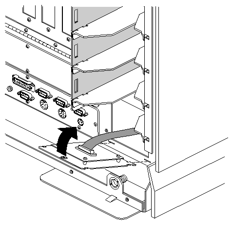
To install the system controller PROM upgrade, you must:
Open the system and remove the system controller board.
Install the new PROM.
Reinstall the system controller board and close the system.
With the system powered off and unplugged, as described in Section 2.3, "System Preparation," perform the following steps:
Pull the back plastic panel from the rear of the system by grasping the bottom edge of the panel and pulling it forward until it unsnaps from the chassis.
Move the back plastic panel forward until it touches the edge of the U-shaped metal bumper at the bottom of the chassis.
Lower the back panel until its upper edge clears the top plastic panel.
Remove the back panel from the chassis.
Remove the nine phillips-head screws holding the rear sheet-metal cover in place (see Figure 2-7).
Lift the rear sheet-metal cover away from the chassis.
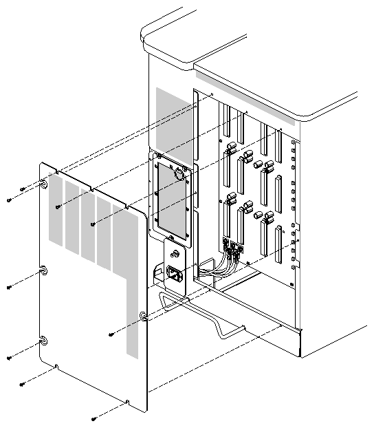
To install the new PROM, you must remove the system controller board. That board is located at the rear of the system in the slot farthest to the right (to the right of the other power boards).
 | Caution: Always observe proper electrostatic-discharge precautions when handling boards. Wear a wrist ground-strap and use an antistatic surface. |
Remove the System Controller board from its slot in the backplane by pulling it straight out (see Figure 2-8). If you have difficulty freeing the board from the backplane, wiggle it slightly top to bottom. However, you should not wiggle it left to right, as this could damage the board or backplane connectors.
Place the system controller board on a soft, antistatic surface, such as an antistatic mat or antistatic foam padding.
 | Note: The soft surface helps absorb shock, preventing possible IC-pin breakage when you install the PROM. |
See Figure 2-8 for the location of the PROM on the system controller board.
Follow these steps to install the PROM upgrade:
Locate the old PROM. Note the orientation of the old PROM — i.e., that the notch goes toward the power brick, as shown in Figure 2-8.
Using a PROM puller, remove the PROM from its socket.
If you don't have a PROM puller, you can remove the PROM with a long, thin screwdriver (or similar device). To do this, gently work the screwdriver under the PROM, starting at the edge farthest from the power brick. Once the screwdriver is under the entire PROM, twist the screwdriver slightly to lift the entire PROM at one time. This must be done carefully, in order to avoid bending the PROM pins.
Install the new PROM in the same orientation as the old one (with the notch toward the power brick). Be sure that each pin goes directly into the corresponding hole in the socket, and that the PROM is fully seated.
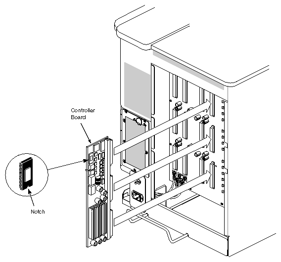
Still using proper static precautions, slide the system controller board back into its slot (the one farthest to the right). The backplane connectors for the system controller are different than the other power board connectors, so there is no chance for confusion.
Reinstall the rear sheet-metal cover. Any easy way to do this is to screw the two bottom screws halfway into their holes, set the sheet-metal cover on those screws, then install the remaining seven screws.
Slide the top edge of the rear plastic panel under the lip of the top plastic panel.
Move the rear plastic panel forward until the bottom touches the chassis.
Move the panel side-to-side until the pins line up with the plastic chassis clips.
Press the panel forward to snap it into place.
Reinstall the system power cable.
Using a null-modem serial cable and a standard serial terminal, test the RSC port and the system controller PROM as follows:
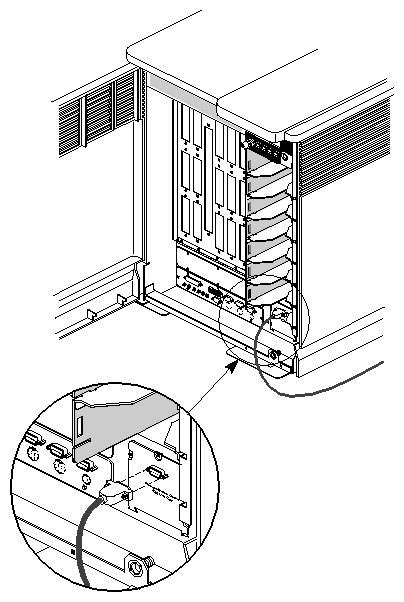
Plug one end of the serial cable into the RSC port on the CHALLENGE server (see Figure 2-9), and the other end of the serial cable into the communications port of your terminal.
Set the terminal to the specifications listed in Table 2-1. Refer to the instruction manual that came with your terminal for details.
Table 2-1. Terminal Settings for Testing the RSC Port
Baud Rate
Duplex
Data Bits
Parity
Stop Bits
Handshaking
9600
Full
8
None
1
XON-XOFF
Power on the terminal.
Power on the deskside system (if it is not already running).
Verify that the deskside system powers on as normal.
From the terminal keyboard, type:
<Ctrl-x>e1<Ctrl-y>
testYou should see the word test appear on your screen. This verifies that the system controller has successfully entered echo mode.
To turn off echo mode, type:
<Ctrl-x>e0<Ctrl-y>
| Note: The testing procedure described here is for use with version 3.10 of the system controller PROM. Earlier versions may respond differently. |
Upgrade of the system controller board PROM in a rack CHALLENGE system is similar to the procedure for a deskside system. In a rack system, the system controller board is located in card cage 1, which is behind the system status panel.
Power off the system as described in Section 2.3, "System Preparation."
Using a Phillips screwdriver, release the quarter-turn captive screw on the right side of the system status panel and swing it out of the way.
Using a Phillips screwdriver, release the two quarter-turn captive screws securing the top of the card cage 1 I/O door and swing it down until it is almost horizontal. Ensure that the system status panel is far enough to the left that the I/O door does not bump into it.
Detach the cable supporting the I/O door and allow the panel to gently pivot toward the floor.
If there is a board lock (at the bottom of the boards), remove it to allow access to the boards.
The system controller board is in card cage 1 in the third slot from the left (on server systems), and is typically connected to an extender board. Remove the system controller board by releasing the top and bottom board extractors and gently pulling the board from its slot.
Upgrade the system controller board PROM as described in Section 2.5.3, "Installing the New PROM." Aside from the extender (if it uses one), the system controller board used in a rack system is identical to the one used in a deskside system. The PROM replacement is therefore also identical.
Reinstall the system controller board. Use the board extractors to gently push the board into place. If there is any unusual resistance, recheck that the board is lined up correctly in its slot, then try again.
If the system had a board lock, reinstall it.
Swing the card cage 1 I/O door up and reattach its supporting cable.
Close the card cage 1 I/O door and latch the two quarter-turn fasteners securing it.
Close the system status panel and latch its quarter-turn fastener.
Test the installation as described in Section 2.6, "Testing the Installation."