This chapter describes how to install the 100Base-T board upgrade into the CHALLENGE and POWER CHALLENGE L (deskside) and XL (rackmount) systems and also the Onyx and POWER Onyx deskside and rackmount systems.
Installation consists of the following major steps:
verifying the kit contents
checking the jumper settings on the board
installing the 100Base-T board into a system
jumpering the backplane (if a VME slot or slots are skipped)
connecting the board to the I/O panel
installing software
verifying installation
 | Note: Since the 100Base-T board has an autosensing 10/100 Mpbs Base-TX interface, it can operate (receive and transmit) with 10-Mbps Ethernet boards. |
This section provides important guidelines to follow during installation.
 | Warning: Installation of these upgrades requires specific training and technical knowledge. These instructions have been provided for use only by Silicon Graphics' system support engineers (SSEs) or other Silicon Graphics-trained personnel. This equipment utilizes electrical power internally that is hazardous if the equipment is improperly disassembled. |
 | Caution: This equipment is extremely sensitive and susceptible to damage caused by electrostatic discharge (ESD). ESD is an electrical discharge (spark) caused by the build-up of electrostatic potential on clothing and other materials. You must use proper ESD preventive measures and observe these precautions: |
Connect a ground strap to your wrist when connecting/disconnecting peripherals.
Be sure that you and all the electrical equipment that you handle during this installation are at ground potential to avoid damage from ESD.
Keep the boards or drives in the antistatic bags provided. Remove a board from its antistatic bag only when you are properly grounded with a ground strap, and only when you are working on the board or installing it.
Do not use an ohmmeter on a board.
Table 2-1 shows the major components of the 100Base-T upgrade (C8-100BT).
Table 2-1. 100Base-T Upgrade Contents
Item | P/N |
|---|---|
Two-port 100 Base-T VME faster Ethernet board | 013-1616-001 |
VME 100Base-T 6U assembly | 013-1618-001 |
Adapter extender 6U-9U | 040-1316-001 |
PCA VME 100Base-T motherboard | 030-0979-001 |
PCA PMC VME 100Base-T | 030-0980-001 |
Driver software | SC4-FASTENET-1.0 |
Cable assembly 100Base-T 6U-bulkhead | 018-0551-001 |
VME 100Base-T bulkhead assembly | 013-1617-001 |
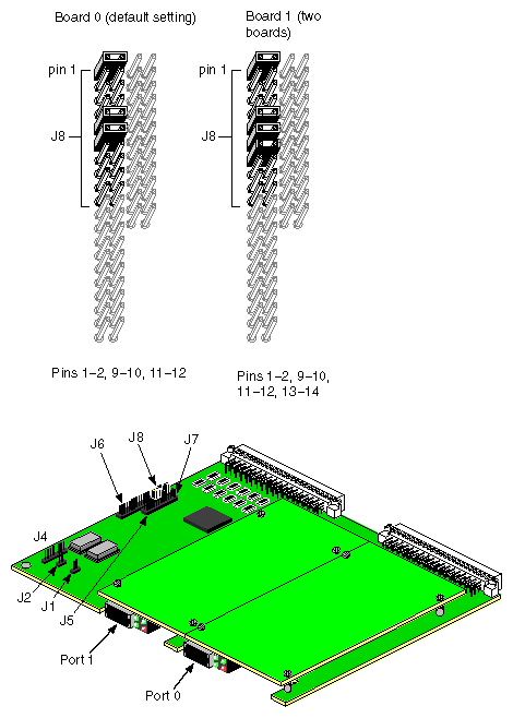
The 100Base-T board should already be configured with the correct jumper settings (see Table 2-2 and Figure 2-1). However, you should double check the settings as outlined in this section.
Table 2-2. 100Base-T Jumper Settings
Jumpers | Function | Setting |
|---|---|---|
J1 | Board reset switch (for manufacturing debug only) | None |
J2 | PCI bus reset switch (for manufacturing debug only) | None |
J3 (Not present) | Not applicable | None |
J4 | In system programming header | None |
J5 | Power-on option | None |
J6 | Power-on option | None |
J7 | Power-on option | None |
J8 | Board addressing | See Figure 2-1 and Note |
| Note: The 100Base-T board comes with the default setting for board 0. |
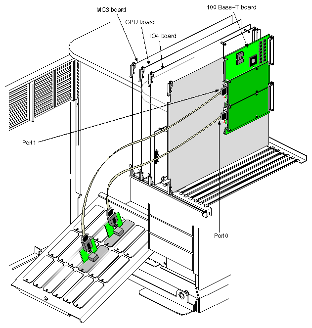
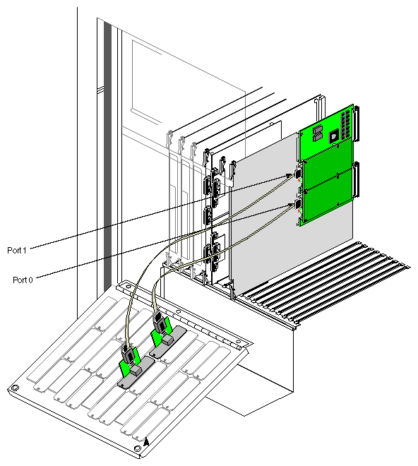
See Figure 2-2 through Figure 2-4 and follow these instructions to install the 100Base-T board into the CHALLENGE and POWER CHALLENGE L (deskside) and XL (rackmount) systems and also the Onyx and POWER Onyx deskside and rackmount systems.
Depending upon the system type and the number of available VME slots, you can install up to two 100Base-T boards (four Ethernet interfaces).
| Note: If you have a rackmount system with the third cardcage option and multiple VMEbuses, it recommended that a single, two port board be configured per VMEbus. This should help improve overall system throughput, given the high data rate capability of the 100Base-T option. In addition, the bus should have no other high speed peripheral interfaces. |
| Caution: The components are extremely sensitive to ESD (electrostatic discharge). Use proper antistatic procedures while handling all components. |
Prior to your arrival, have the customer back up the system. Power off the system using a command such as the following:
shutdown -y -g0
Remove all cables from the I/O door, then open up the door.
Select the appropriate board number address for the 100Base-T board, by changing the jumper settings (see Table 2-2 and Figure 2-1) for more information.
Caution: If you are installing more than one 100Base-T board, ensure that each board is assigned a different board number address. See Table 2-2 and Figure 2-1. Note: If you are installing only one board, the 100Base-T board should already be correctly configured as board number 0. Depending on the number of available VME slots, a system can support up to two 100Base-T boards. Pick an available VME board slot (refer to Figure 2-3, Figure 2-4, and Table 2-3). When installing VME boards, use the leftmost available slot first and continue installing boards to the right without skipping any slots. This sequence is required since the backplane loops the signals from the left slot to the next slot to the right. Any skipped or open slot interrupts the signal flow to subsequent slots.
Caution: Even if you are using a VME slot located farthest to left, it is a good idea to check the backplane for possible jumpers from a previous installation. If backplane jumpers for this slot are installed, remove them. Note: If you need to skip a VME slot, remember to install backplane jumpers in the appropriate location. See Section 2.5, "Jumpering a Skipped VME Slot," for more details. Table 2-3. VME Slot Positions for CHALLENGE and Onyx Systems
System Chassis
VME Slot Positions
CHALLENGE L (deskside)
7 through 11
CHALLENGE XL (rackmount)
Cardcage 1 (N/A)
Cardcage 2 (17 through 21)
Cardcage 3 (2 through 21)Onyx deskside
5 through 7
Onyx rackmount
Cardcage 2 (N/A)
Cardcage 2 (13 through 15)
Cardcage 3 (2 through 4 and 13 through 15)Install the board into the VME slot. You should hear and feel the board snap into the board ejectors and backplane connectors. The board is now seated in the backplane.
Resecure the board lock bars across the top and bottom of the boards in the cardcage as applicable.
Next, remove a spare I/O plate from the I/O connector panel for each channel on the board.
Caution: If you have a deskside system with RealityEngine graphics or Extreme graphics (AB4 or AB5), do not use the I/O plate positions on the connector panel that are called out in Figure 2-2. Attach the 100Base-T bulkhead to the I/O panel.
Attach the cable assembly to the port 0 or port 1 connector on the board.
Reattach any I/O cables that have been removed.
With the I/O door still open, power on the system and watch the LEDs on the front panel of the 100Base-T board(s) to see if they are on.
Close the I/O door.
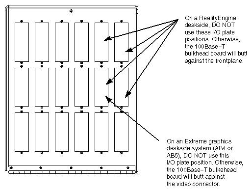
| Caution: There are I/O connector plate positions on certain deskside configurations that cannot be used for the 100Base-T bulkhead as shown in Figure 2-2. |
| Caution: If you have a deskside system with RealityEngine graphics or Extreme graphics (AB4 or AB5), do not use the I/O plate positions on the connector panel that are called out in Figure 2-2. |
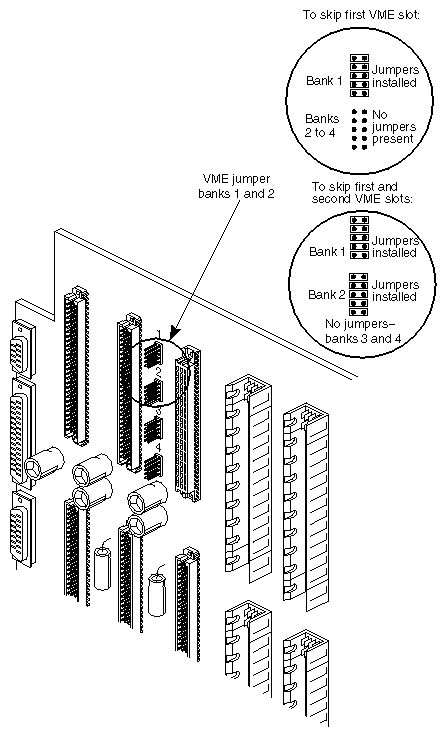
VME boards should be installed left to right, starting with the first available slot on the left. However, skipping a slot is occasionally required to fit oversized VME boards or improve air flow. A slot can be skipped if jumper blocks are placed on the appropriate VME jumper block pins (or headers) located on the rear of the backplane (see Figure 2-5).
| Note: If you install the VME boards in order (from left to right) without skipping, starting with the VME slot farthest to the left, then no jumpering is required. |
The general guideline is to insert jumpers into the jumper banks corresponding to the VME slot number that you are skipping. For example, if you are skipping the first VME slot, you need to insert jumpers into jumper bank 1. See the following additional examples:
If you are skipping the first VME slot (for example, slot 7 in a CHALLENGE L system) to use the next VME slot, you must place five jumpers in the jumper bank, designated as slot 1 (see Figure 2-5).
If you are skipping the first two VME slots and wish to use the third VME slot, you must place jumpers in jumper banks 1 and 2.
If you wish to skip over VME slots, for example, from the first VME slot to the third VME slot, you must place jumpers in bank 2.
Follow these instructions to install and reconfigure the 100Base-T board software:
| Note: The 100Base-T board requires IRIX version 5.3 or 6.2 or later for proper support. |
Power-on the system, open up a shell, and become superuser.
Insert the 100Base-T CD-ROM and use inst to install the software. For example,
inst -f /CDROM/dist/if_vfe
Rebuild the kernel by entering the following command at the shell prompt as superuser:
autoconfig -v
This command announces the presence or absence of all optional boards in the system as follows:
exprobe spaced if_vfe adapter n
if_vfe, adapter n exprobe space
The variable n indicates the VMEbus or adapter number.
Reboot and reconfigure the system.
After powering on the system, here is what you see at boot time (without showconfig set).
If only board 0 is installed:
IP-6200 100Base-TX EtherNet Ver 1.0 (0612A00) - A16[0x6000], A32[0x19500000]
board 1 gives:
IP-6200 100Base-TX EtherNet Ver 1.0 (0612A00) - A16[0x7000], A32[0x19600000]
| Note: The variable (0612A00)may different in your bootup display. |
The hinv command will not recognize the 100Base-T board(s) even if the 100Base-T software driver has been installed and configured.