This chapter contains the following topics:
“About Performing a New Installation and Configuring the Software on an SGI Cluster”
“(Conditional) Configuring External Domain Name Service (DNS) Servers ”
“Synchronizing the Software Repository, Installing Software Updates, and Cloning the Images”
“Verifying Power Operations and Configuring Power Management”
“(Optional) Configuring a Backup Domain Name Service (DNS) Server ”
SGI installs operating system software on each cluster system before factory shipment occurs. The topics in this chapter include the additional procedures that you need to complete in order to configure the system for your site.
If you want to completely reinstall the operating system and all other software, the topics in this chapter enable you to complete that task. For example, you might need to reinstall the operating system to meet site requirements or to recover a system in case of a disaster.
Figure 3-1 depicts the software installation process.

Table 3-1 shows the installation and configuration procedures to follow if you want to install the a cluster system from scratch. The cluster installation process is the same for SGI ICE clusters and SGI Rackable clusters. In the case of the SGI Rackable clusters, the SMC software omits the steps that install images on RLCs and on SGI ICE compute nodes. In this case, you reinstall the operating system on the nodes and configure everything yourself.
Table 3-1. SGI ICE System Installation and Configuration Process
Step | Task | See |
|---|---|---|
1 | (Conditional) Prepare the cluster to run the migrate-sgi-mc script. | |
2 | Plan the image installation method. | |
3 | Prepare to install the cluster software. | |
4 | (Conditional) Configure a static address for the baseboard management controller (BMC) on the admin node. Complete this step only if your site practices require a static IP on the BMC. | |
5 | (Optional) Configure a highly available admin node or a highly available rack leader controller (RLC). | |
6 | Boot the system. | |
7 | Install the operating system on the admin node. You can install the Red Hat Enterprise Server (RHEL), SLES, or CentOS operating system. | |
8 | Run the cluster configuration tool. Complete the initial cluster configuration tasks, which include the following:
| |
9 | (Conditional) Configure external domain name service (DNS). If you want to configure network address translation, you also need to configure an external DNS. | “(Conditional) Configuring External Domain Name Service (DNS) Servers ” |
10 | Synchronize the repository updates, apply the latest patches to the newly installed software, and clone the images. | “Synchronizing the Software Repository, Installing Software Updates, and Cloning the Images” |
11 | (Conditional) Download the Intel Manycore Platform Software Stack (MPSS). | |
12 | (Conditional) Run the migration script | “(Conditional) Running the Migration Script and Editing the Cluster Definition File” |
13 | Configure the switches. | |
14 | Use the discover command to install and configure software on the rack leader controller and the flat compute nodes. | |
15 | Configure power management. | “Verifying Power Operations and Configuring Power Management” |
16 | (Conditional) Verify that the blade daemons are running | |
17 | (Optional) Configure a backup domain name service (DNS) server on a flat compute node. | “(Optional) Configuring a Backup Domain Name Service (DNS) Server ” |
17 | Configure the InfiniBand subnetworks. | |
19 | Configure optional features. |
Complete the procedure in this topic if you want to upgrade an existing cluster from SMC 1.7.5 to SMC 3.0.
The migrate-sgi-mc script ensures a smooth transition when you upgrade the SMC software on your cluster from SMC 1.7.5 to SMC 3.0. The conversion process requires you to back up your current cluster to a network location, run the migrate-sgi-mc script, and install SMC 3.0.
The following procedures explain the steps that prepare your system for migration if you plan to install SMC 3.0 as part of a cluster migration from SMC 1.7.5:
The following procedure explains how to verify the payloads and their kernels and how to export the kernels.
Procedure 3-1. To verify the SMC 1.7.5 payloads and kernels
Use the cd(1) command to change to the directory that hosts the payload files, and use the ls(1) command to list the payload files:
For example:
# cd /opt/sgi/sgimc/imaging/root/payloads
# ls
Compute-SLES-11-3          payload-test-11-3         .vcs.profile
Compute-SLES-11-3-legacy   ss-test                   windows-cleint-test
Compute-SLES-11-3-migrate  importedComputeSles11-3   .vcs.entries
Use the cd(1) command to change to one of the payload directories, and use the vcs list command to list the kernels.
For example:
# cd Compute-SLES-11-3
# vcs list
vcs - Version 1.4.0 Build 3
Copyright (c) 2006-2013 Silicon Graphics, Inc.  All rights reserved.
=============================================================================
java vendor "Oracle Corporation"
java version "1.7.0_21"
OpenJDK Runtime Environment (build 1.7.0_21-b02)
OpenJDK 64-Bit Server VM (build 23.7-b01, mixed mode)
=============================================================================
payloads
------------------------------------
  Centos6.6Brian (2)
  Compute-SLES-11-3 (3)
  Compute-SLES-11-3-legacy (1)
  importedComputeSles11-3 (1)
  payload-test-11-3 (1)
  ss-test (1)

kernels
------------------------------------
  Compute-SLES-11-3 (1)
  RAID-SLES-11-3 (1)
  centos6.6brian (1)
  importedComputeSles11-3 (1)

images
------------------------------------
  Compute-SLES-11-3 (4)
  RAID (1)
  centos6.6Brian (1)
  importedComputeSles11-3 (1)
The preceding output shows that payload Compute-SLES-11-3 includes kernels. In addition, the kernels are checked in. This payload is ready to be checked out. The next step explains what to do if the payload does not include checked-in kernels.
(Conditional) Use the SMC interface to add a kernel to the payload, and check in the kernel.
Complete this step if the preceding command shows that there are no kernels in this particular payload.
Before you migrate to SMC 3.1, all payloads must have kernels, and all kernels must be checked in.
Change to the directory in which you want to store the checked-out payload files.
This can be any directory on the SGI cluster.
For example, type the following command to change to the .../root directory:
# cd /opt/sgi/sgimc/imaging/root
Use the vcs checkout command, in the following format, to check out the payload to the .../root directory:
vcs checkout -R payloads -M:payload_name -r:1
For payload_name, specify the name of the payload.
For example:
# vcs checkout -R payloads -M:Compute-SLES-11-3 -r:1
Proceed as follows:
If there are additional payloads you need to examine and check out, repeat the preceding steps for the additional payloads.
If the output shows that this particular payload and kernels are checked into VCS, and this is the last or only payload you need to examine, proceed to the following:
The following procedure explains how to back up the current cluster configuration to a network location and how to run the dbix script.
The dbix script exports all SMC database entries into a file.
Procedure 3-2. To back up the SMC 1.7.5 configuration to a network location and export the database entries
Back up the SGI cluster to a network location.
The migration script performs a major transformation on your cluster. In particular, make sure that the following are included in the backup:
The entire /opt/sgi/sgimc/etc directory.
All payloads.
Use the cd(1) command to change to the directory that hosts the exported payloads.
For example, in this procedure, this directory is /opt/sgi/sgimc/imaging/root .
Type the following command to export all SMC database entries:
# dbix -x > dbix.txt
Copy file dbix.txt to a backup location on your network.
Proceed to the following:
The SMC discover command installs software images on the nodes and facilitates adding nodes to a cluster. You use the discover command during the initial installation, and you can use the discover command again later if you want to reconfigure a node's network settings or you want to update the cluster after a hardware equipment change.
SGI supports three different file transfer methods for use during installation. These methods are rsync (default), UDPcast, and BitTorrent. The BitTorrent method is supported for legacy clusters.
The fastest image installation method for your cluster depends on the cluster's topology. Before you begin the installation, familiarize yourself with the image transport and installation methods and make sure that your installation plan uses the method that is most appropriate for your cluster. Your site network configuration can also affect the speed at which the discover command can push software to nodes.
The following procedure explains how to determine the image installation method that is most appropriate for your cluster.
Procedure 3-3. To plan the installation method
Consider using the cluster definition file.
Perform the following steps if the cluster has a working slot at this time:
Type the following command to generate a cluster definition file:
discover --show-configfile > file_name
For file_name, type a name for the cluster definition file.
Save the cluster definition file in a safe place on a computer off of the cluster.
If you have a working cluster definition file, you can supply the file as input to the discover command and to the configure-cluster command. The file enables you to complete the installation and configuration process complete more quickly. Without a cluster definition file, you need to power on and power off each component during the configuration process. The cluster definition file supplies the information that you would typically define by using the menus in the cluster configuration tool. When you specify a cluster configuration file as input to the configure-cluster command or to the discover command, the command reads in the options from the file and implements them in the cluster.
If you plan to reinstall the software on a new cluster that you just received from SGI, you can obtain the cluster definition file used in the manufacuring process from your SGI representative.
For more information about the cluster definition file, see the following:
Determine the number and type of nodes that need to be imaged.
When you run the discover command during system installation, only the flat compute nodes and the rack leader controllers (RLCs) receive software images. The SGI ICE compute nodes receive their images directly from their RLC, so you do not need to consider the number of SGI ICE compute nodes in this calculation. Count the number of nodes as follows:
If you have five or six nodes, the default transport method, rsync, is appropriate. For example, if you have three RLCs and two flat compute nodes, you can use the default method. You do not need to consider the number of SGI ICE compute nodes that are associated with each RLC. You do not need to edit your cluster definition file, nor do you need to plan for any additional command line options for the discover command.
You do not need to complete the rest of this procedure. Proceed to the following:
If you have more than five or six nodes, consider using the UDPcast transport method. If you have hundreds of flat compute nodes, you most definitely need to consider using UDPcast.
To use UDPcast, either plan to provide additional arguments to the discover command when you run it (later in the installation process) or edit the cluster definition file at this time.
If you specify options on the discover command line, those options override those that appear in the configuration file. If you prefer to specify the UDPcast transport on the discover command line, plan to include the udpcast argument.
For example, if you have three RLCs and 200 flat compute nodes, you can specify the following command:
# discover --leaderset 1,3,transport=udpcast --nodeset 1,200,transport=udpcast --configfile myfile --all
If you want to edit the cluster definition file at this time, complete the following steps:
Obtain a copy of the cluster definition file from your sales representative or generate one by typing the following command:
discover --show-configfile > filename
For filename, specify the output file name.
Open the cluster definition file from within a text editor.
Search in the file for each block of text that describes a node. Each node block begins with the keyword temponame=. For example, the following text block describes one of the RLCs:
temponame=r1lead, mgmt_bmc_net_name=head-bmc, mgmt_bmc_net_macs=00:25:90:58:8b:75,
mgmt_net_name=head, mgmt_net_macs=00:25:90:58:8a:94/00:25:90:58:8a:95,  redundant_mgmt_network=yes,
switch_mgmt_network=yes, mic=0, dhcp_bootfile=grub2,  conserver_logging=yes, conserver_ondemand=no,
console_device=ttyS1
At the end of each node definition block, add the following:
, transport=udpcast
Save and close the file.
Proceed to the following:
The following procedure explains the information you need to obtain before you begin working with the cluster. Your installation session can proceed more quickly if you gather information before you begin.
Procedure 3-4. To prepare for an installation
Contact your site's network administrator to obtain network information.
Obtain the information to use when you configure the baseboard management controller (BMC) of the admin node. Your network administrator can provide an IP address, a hostname, or a fully qualified domain name (FQDN) for each of the following addresses:
(Optional) The current IP address of the BMC on the admin node. You can set the BMC address from a serial console if you do not have this information.
The address you want to set for the BMC.
The netmask you want to set for the BMC.
The default gateway you want to set for the BMC.
Obtain the following information to use when you configure the network for the SGI ICE system:
Hostname
Domain name
IP address
Netmask
Default route
Root password
Obtain the following information about your site's house network:
IP addresses of the domain name servers (DNSs)
(Conditional) Obtain information for one or more routed management networks. SGI recommends that you configure one or more routed management networks for every 300-500 flat compute nodes in your cluster. When you have a large number of flat compute nodes, a routed management network reduces the run-rate overhead that is associated with broadcast traffic. Obtain the following information for each routed management network that you want to configure:
A name for the routed management network. For example, head2.
Subnetwork address.
Network mask for the subnetwork address.
BMC subnetwork address.
Network mask for the BMC subnetwork address.
(Optional) Obtain the configuration file for your cluster from your SGI representative.
The configuration file contains system data, for example, the MAC address information for the nodes. If you have these addresses, the node discovery process can complete more quickly. For more information about the cluster definition file, see the following:
Perform the procedure in this topic if one of the following is true:
Your site practices require a static IP address for the BMC.
You want to configure a high availability admin node. In this case, perform this topic's procedure on the BMCs on each of the two admin nodes.
When you set the IP address for the BMC on the admin node, you ensure access to the admin node when the site DHCP server is inaccessible.
The following procedures explain how to set a static IP address.
Procedure 3-6. Method 2 -- To change the IP address from the admin node.
Log into the admin node as the root user.
Type the following command to retrieve the current network settings:
# ipmitool lan print 1
In the output from the preceding command, look for the IP Address Source line and the IP Address line.
For example:
IP Address Source       : DHCP Address
IP Address              : 128.162.244.59
Note the IP address in this step and decide whether or not this IP address is acceptable. The rest of this procedure explains how to keep this IP address or to set a different static IP address.
Type the following command to specify that you want the BMC to have a static IP address:
# ipmitool lan set 1 ipsrc static
This step specifies that the IP address on the BMC is a static IP address, and this step sets the IP address to the IP address that is currently assigned to the BMC. If you want to set the IP address to a different IP address, proceed to the following step. If the current IP address is acceptable, you do not need to perform the next step.
(Optional) Set a different IP address.
Complete this step if you want to set the static IP address to be different from the IP address that is set currently.
Type ipmitool commands in the following format:
ipmitool lan set 1 ipaddr ip_addr
ipmitool lan set 1 netmask netmask
ipmitool lan set 1 defgw gateway
The arguments are as follows:
Argument Specification
ip_addr The IP address you want to assign to the BMC.
netmask The netmask you want to assign to the BMC.
gateway The gateway you want to assign to the BMC.
For example, you can type the following commands to set the IP address to 100.100.100.100:
# ipmitool lan set 1 ipaddr 100.100.100.100
# ipmitool lan set 1 netmask 255.255.255.0
# ipmitool lan set 1 defgw 128.162.244.1
Proceed to one of the following:
If you want to configure a high availability admin node, proceed to the following:
If you want to configure a traditional admin node, proceed to the following:
SGI supports the ability to configure the admin node and rack leader controllers (RLCs) as highly available nodes in an SGI ICE cluster. If you want to enable high availability (HA) on the admin node or on the RLCs, contact your SGI representative.
You can configure the cluster to boot from one, two (default), three, four, or five slots. A slot consists of all the partitions related to a Linux installation.
A multiple-slot disk layout is also called a cascading dual-root layout or a cascading dual-boot layout . The installer creates the same disk layout on all nodes. Each slot includes the following:
A /boot partition.
A /, or root, partition.
A /boot/efi partition. A slot includes this partition only if the node is an EFI node.
When you insert an SMC operating system installation disk and power-on the admin node, you can select a boot method from the GNU GRUB menu. If you select Install: Wipe Our and Start Over: Prompted, which is the default, the installer creates two slots and writes the initial installation to slot 1. After the system is installed, you cannot change the number of slots without destroying the data on the disks.
After you install a multislot cluster, you can boot the cluster with the operating system of your choice. This ability might be useful if you ever want to test an operating system or other software because you can roll back an upgrade completely.
The following are some other characteristics of single-boot systems and multiple-boot systems:
| Multiple-boot | Single-boot |
| You can install different operating systems, or different operating system versions, into different slots. Note that if you have an SGI ICE cluster, the admin node and the RLCs must have the same operating system installed. | You can install only one operating system for the entire cluster. |
| RLCs and flat compute nodes boot from their own disk. Data is retained in the master boot record (MBR). | RLCs and flat compute nodes boot from the boot partition in the slot that is currently configured as the boot slot. Only the admin node retains data in the MBR. |
| RLC and flat compute node software is reinstalled from the admin node. | Software on the RLCs and flat compute nodes is reinstalled over the network. |
| As you increase the number of slots, you decrease the amount of disk space per slot. SGI recommends a minimum of 100 GB per slot. | A single slot uses all available disk space. |
If all slots on your cluster are running either SGI Tempo 2.9.0 (or later) or SMC 3.0 (or later), then your cluster uses the partition layout designed for the SGI Tempo 2.9.0 and later releases. If you upgraded your cluster, it is possible that you have the legacy partition layout on one or more slots. For information about partitions, including those for legacy partitions, see the following:
Appendix D, “Partition Layout Information”
| Note: SMC supports both EFI BIOS and legacy x86_64 BIOS. If you are not sure which BIOS your cluster supports, contact your sales representative. |
The following procedure explains how to boot the system and begin the installation.
Procedure 3-7. To boot the system
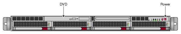
Power-on the admin node.
As Figure 3-2 shows, the power-on button is on the right of the admin node.
Insert the SGI Admin Node Autoinstallation DVD into the DVD drive on the admin node.
Use the arrow keys to select one of the boot options, press Enter, and monitor the installation.
On the GNU GRUB boot menu, the options are as follows:
Display Instructions
Select this option if you want information about custom boot parameters. This option displays information and returns to the boot menu.
Each boot option has a set of default behaviors. In addition to the default behaviors, you can specify custom boot parameters if you select one of the following options:
Install: Install to Designated Slot
Install: Wipe Out and Start Over: Prompted
Install: Custom, type 'e' to edit kernel parameters
If you think you might want to specify one or more custom boot parameters, for example, console=, select the Display Instructions option and familiarize yourself with these parameters before you select an actionable parameter.
Install: Install to Designated Slot
Select this option if you have an open slot on your cluster, and you want to install an operating system in the slot. If you select this option, only the open slot is affected. All other slots remain as configured.
Install: Wipe Out and Start Over: Prompted
Select this option if you want to reinstall the cluster. This options destroys all information currently on the cluster. The installer partitions the admin node with the specified number of slots, and the installer writes the initial installation to the designated slot. In the factory, SGI configures systems by default with two slots, and the installation is in slot 1. For example, for an initial installation, select this option.
Rescue: Prompted
Select this option to create a troubleshooting environment.
Install: Custom, type 'e' to edit kernel parameters
Select this option if you want to perform a custom installation. This option lets you supply all boot options as command line parameters, as opposed to specifying boot options in respone to the system prompts that the other methods offer. More information is available in Display instructions. SGI recommends this option only for users with installation experience.
All the options launch you into an installation dialog, and at the end of the dialog, the final question asks you to confirm your choices. In this way, you have the chance to cancel your choices and return to the GNU GRUB boot menu to start over. The following are some of the installation dialog prompts that appear when you select a boot option:
Enter number of slots to allow space for: (1-5):
Type 1, 2, 3, 4, or 5, and press Enter.
This dialog question appears only if you select Install: Wipe Out and Start Over: Prompted from the GNU GRUB menu.
Enter which slot to install to:
Type 1, 2, 3, 4, or 5, and press Enter.
This dialog question appears only if you select Install: Install to Designated Slot from the GNU GRUB menu.
Destructively bypass sanity checks? (y/n):
If you type y and press Enter, the installer proceeds without checking to see if there is any data in the partition.
If you type n and press Enter, the installer checks to see if there is data in the partition before proceeding.
Additional parameters (like console=, etc):
If you want to specify any additional boot parameters, type them in a comma-separated list and press Enter.
For information about the boot parameters that are available, select Display Instructions from the GNU GRUB menu and press Enter.
OK to proceed? (y/n):
If you type y and press Enter, the boot proceeds.
If you type n and press enter, the menu returns you to the main GNU GRUB menu.
The installation can take several minutes.
Remove the operating system installation DVD.
At the # prompt, type reboot .
This is the first boot from the admin node's hard disk.
(Optional) Suppress log messages.
If you want to suppress the admin node's log message output to the screen during the boot, edit file /etc/syscontrol.conf and add the following line to the top of the file (line 1):
kernel.printk = 2 4 1 7
In the preceding kernel.printk line, the spaces between the numbers 2 4 1 7 are Tab characters.
Proceed to the following:
The cluster systems support the Red Hat Enterprise Linux (RHEL) operating system, CentOS, and the SLES and operating system. Use one of the following procedures to install your operating system software on the admin node:
| Note: In SGI documentation, you can assume that feature descriptions for RHEL platforms also pertain to CentOS platforms unless otherwise noted. |
This section describes how to configure Red Hat Enterprise Linux 6 on the admin node.
Procedure 3-8. To install RHEL 6 on an SGI ICE admin node
Use one of the following methods to connect to the admin node:
Through the intelligent platform management interface (IMPI) tool
Through the console attached to the cluster
Through a separate keyboard, video display terminal, and mouse
Use a text editor, such as vi or vim, to open file /etc/sysconfig/network-scripts/ifcfg-eth0 .
Add lines for the IPADDR, NETMASK , and NETWORK values appropriate for your site network to file /etc/sysconfig/network-scripts/ifcfg-eth0 .
For example:
IPADDR=128.162.244.88
NETMASK=255.255.255.0
NETWORK=128.162.244.0
Save and close file /etc/sysconfig/network-scripts/ifcfg-eth0 .
Use a text editor to create file /etc/sysconfig/network .
Add the following three lines to file /etc/sysconfig/network :
NETWORKING=yes
HOSTNAME=admin_node_hostname
GATEWAY=gateway_IP_address
For admin_node_hostname, type the hostname you want to assign to the admin node.
For gateway_IP_address, type the IP address of the gateway for your house network.
For example:
NETWORKING=yes
HOSTNAME=my-system-admin
GATEWAY=128.162.244.1
Save and close file /etc/sysconfig/network.
Use a text editor to open file /etc/hosts.
Add a line in the following format to file /etc/hosts :
admin_node_IP admin_node_FQDN admin_node_hostname
The variables in the preceding line are as follows:
For admin_node_IP, type the IP address of the admin node.
For admin_node_FQDN, type the fully qualified domain name (FQDN) of the admin node.
For admin_node_hostname, type the hostname of the admin node.
For example, add the following line:
128.162.244.88 my-system-admin.domain-name.mycompany.com my-system-admin
Save and close file /etc/hosts.
Type the following command to set the admin node hostname:
# hostname admin_node_hostname
For admin_node_hostname, type the hostname of the admin node.
For example:
# hostname my-system-admin
Use a text editor to create file /etc/resolv.conf .
Add lines to file /etc/resolv.conf that specify the search domain and the domain name service (DNS) servers at your site.
Later in the configuration process, when you run the cluster configuration tool, the tool uses the DNS servers you specify in this step for its defaults.
Specify lines with the following format:
search search_domain
nameserver name_server_IP
nameserver name_server_IP
The following is an example resolv.conf file:
search mydomain.com
nameserver 192.168.0.1
nameserver 192.168.0.25
Type the following nscd(8) command to force the invalidation of the name service cache daemon:
# nscd -i hosts
Type the following commands, in the order shown, to restart services:
# /etc/init.d/network restart
# /etc/init.d/rpcbind start
# /etc/init.d/nfslock start
Type the following command to retrieve the admin node's current time zone information:
# strings /etc/localtime | tail -1
CST6CDT,M3.2.0,M11.1.0
The previous output shows the admin node set to US Central time. If the output you see is not correct for this cluster, perform the following steps:
Type the following command to change to the directory that contains the time zone configuration files:
# cd /usr/share/zoneinfo
Select a file from that directory that describes the time zone for the admin node.
Type the following commands to enable the new time zone configuration file.
For example:
# /bin/cp -l /usr/share/zoneinfo/time_zone_file /etc/localtime.$$
# /bin/mv /etc/localtime.$$ /etc/localtime
For time_zone_file, type the name of the time zone file that you need from the /usr/share/zoneinfo directory.
For example, type the following commands to change the admin node's time zone to US Pacific time:
# /bin/cp -l /usr/share/zoneinfo/PST8PDT /etc/localtime.$$
# /bin/mv /etc/localtime.$$ /etc/localtime
Type the following command to confirm the time zone:
# strings /etc/localtime | tail -1
PST8PDT,M3.2.0,M11.1.0
(Conditional) Edit file /etc/ntp.conf to direct requests to the network time protocol (NTP) server at your site.
Complete the following steps if you want to direct requests to your site's NTP server instead of to the public time servers of the pool.ntp.org project:
Use a text editor to open file /etc/ntp.conf .
Insert a pound character (#) into column 1 of each of each line that includes rhel.pool.ntp.org .

Note: Do not edit or remove entries that serve the cluster networks. At the end of the file, add a line that points to your site's NTP server.
The following is an example of a correctly edited file:
# Use public servers from the pool.ntp.org project.
# Please consider joining the pool (http://www.pool.ntp.org
# server 0.rhel.pool.ntp.org
# server 1.rhel.pool.ntp.org
# server 2.rhel.pool.ntp.org
server ntp.mycompany.com
The preceding output has been truncated at the right for inclusion in this guide.
Type the following command to restart the NTP server:
# /etc/init.d/ntpd restart
(Conditional) Type a tilde character (~) and then a period character (.) to exit from the IPMI tool.
Complete this step if you connected to the system through the IPMI tool.
(Optional) Configure the system so that you can perform the installation from a VGA screen and can perform later operations from a serial console.
If you want to enable this capability, perform the following steps:
Use a text editor to open file /boot/grub/menu.lst .
Search the file for the word kernel at the beginning of a line.
Add the following to the kernel line: console=type.
For example:
kernel /boot/vmlinuz-2.6.16.56-0.12-smp root=/dev/disk/by-label/sgiroot console=ttyS1,38400n8
splash=silent showopts
Add the console=type parameter to the end of every kernel line. By default, this is set to ttyS1,38400n8. You might have ttys2, for example.
Later, if you want to access the admin node from only a VGA, you can remove the console= parameters.
Proceed to the following:
The SLES YAST interface enables you to install the SLES operating system on a cluster. To navigate the YAST modules, use key combinations such as the following:
The Tab key moves the cursor forward, and the Shift + Tab keys move the cursor backward.
The arrow keys move the cursor up, down, left, and right.
To use shortcuts, press the Alt key + the highlighted letter.
Press Enter to complete or confirm an action.
Press Ctrl + L to refresh the screen.
For more information about navigation, see Appendix A, “YAST Navigation”.
The following procedure explains how to use YAST to install SLES 11 on a cluster.
Procedure 3-9. To install SLES 11 on an SGI ICE admin node
Connect to the admin node by one of the following methods:
Through the intelligent platform management interface (IMPI) tool
Through the console attached to the cluster
Through a separate keyboard, video display terminal, and mouse
On the Language and Keyboard Layout screen, complete the following steps:
Select your language
Select your keyboard layout
Select Next.
On the Welcome screen, select Next.
On the Hostname and Domain Name screen, complete the following steps:
Type the hostname for this cluster.
Type the domain name.
Clear the box next to Change Hostname via DHCP. The box appears with an X in it by default, but you need to clear this box.
Select Assign Hostname to Loopback IP. Put an X in this box.
Select Next.
On the Network Configuration screen, complete the following steps:
Select Change. A pop-up window appears.
On the pop-up window, choose Network Interfaces.
On the Network Settings screen, complete the following steps:
Highlight the first network interface card that appears underneath Name.
Select Edit.
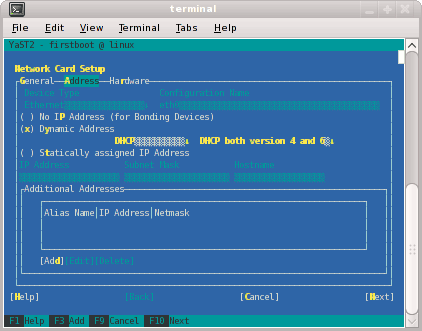
On the Network Card Setup screen, specify the admin node's house/public network interface.
Figure 3-3 shows the Network Card Setup screen.
Complete the following steps:
Select Statically Assigned IP Address . SGI recommends a static IP address, not DHCP, for the admin node.
In the IP Address field, type the system's IP address.
In the Subnet Mask field, type the system's subnet mask.
In the Hostname field, type the system's fully qualified domain name (FQDN). SGI requires you to type an FQDN, not the system's shorter hostname, into this field. For example, type mysystem-admin.mydomainname.com. Failure to supply an FQDN in this field causes the configure-cluster command to fail.
Select Next.
You can specify the default route, if needed, in a later step.
On the Network Settings screen, complete the following steps:
Select Hostname/DNS.
In the Hostname field, type the system's fully qualified domain name (FQDN).
In the Domain Name field, type the domain name for your site.
Put an X in the box next to Assign Hostname to Loopback IP.
In the Name Servers and Domain Search List, type the name servers for your house network.
Back at the top of the screen, select Routing .
The Network Settings > Routing screen appears.
In the Default Gateway field, type your site's default gateway.
Select OK.
On the Network Configuration screen, click Next.
The Saving Network Configuration screen appears and saves your configuration.
On the Clock and Time Zone screen, complete the following steps:
Select your region.
Select your time zone.
(Optional) In the Hardware Clock Set To field, choose Local Time or accept the default of UTC.
Select Next.
This step synchronizes the time in the BIOS hardware with the time in the operating system. Your choice depends on how the BIOS hardware clock is set. If the clock is set to GMT, which corresponds to UTC, your system can rely on the operating system to switch from standard time to daylight savings time and back automatically.
On the Password for System Administrator “root” screen, complete the following steps:
In the Password for root User field, type the password you want to use for the root user.
This password becomes the root user's password for all the nodes on the ICE system. These nodes are as follows:
admin node
Flat compute nodes
Rack leader controller (RLC) (Optional)
SGI ICE compute nodes (blades) (Optional)
In the Confirm password field, type the root user's password again.
In the Test Keyboard Layout field, type a few characters.
For example, if you specified a language other than English, type a few characters that are unique to that language. If these characters appear in this plain text field, you can use these characters in passwords safely.
Select Next.
On the User Authentication Method screen, select one of the authentication methods and select Next.
Typically, users accept the default (Local).
On the New Local User screen, create additional user accounts or select Next.
If you do not create additional users, select Yes on the Empty User Login warning pop-up window, and select Next.
On the Installation Completed screen, select Finish.
Type a tilde character (~) and then a period character (.) to exit from the IPMI tool.
Log into the admin node, open file /etc/hosts within a text editor, and verify that the admin node's fully qualified domain name (FQDN) and hostname are entered correctly.
For example, the following /etc/hosts file entry contains the correct data in the three required fields and is correct for an admin node with an IP address of 100.100.100.100, an FQDN of mysystem-admin.mydomain.com, and a hostname of mysystem-admin:
100.100.100.100 mysystem-admin.mydomain.com mysystem-admin
Make sure that the /etc/hosts file on the admin node contains the required information. If it does not, edit the /etc/hosts file to contain the three required fields as the preceding example shows.
Confirm that the system is working as expected.
If necessary, restart YAST to correct settings.
(Optional) Configure the system so that you can perform the installation from a VGA screen and can perform later operations from a serial console.
If you want to enable this capability, perform the following steps:
Use a text editor to open file /boot/grub/menu.lst .
Search the file for the word kernel at the beginning of a line.
Add the following to the kernel line: console=type.
For example:
kernel /boot/vmlinuz-2.6.16.56-0.12-smp root=/dev/disk/by-label/sgiroot console=ttyS1,38400n8
splash=silent showopts
Add the console=type parameter to the end of every kernel line. By default, this is set to ttyS1,38400n8. You might have ttys2, for example.
Later, if you want to access the admin node from only a VGA, you can remove the console= parameters.
Proceed to the following:
Configuring the cluster includes the following actions:
Creating repositories for software installation files and updates.
Installing the admin node's cluster software.
Configuring the cluster subdomain and examine other network settings. The cluster subdomain is likely to be different from the eth0 domain on the admin node itself.
Configuring the NTP server.
Installing the cluster's software infrastructure. This step can take 30 minutes.
Configuring the house network's DNS resolvers.
The following procedure explains how to use either the cluster configuration tool or the cluster definition file to configure the cluster:
Procedure 3-10. To configure the cluster
Locate your site's SGI software distribution DVDs or verify the path to your site's online software repository.
You can install the software from either physical media or from an ISO on your network.
From the VGA screen, or through an ssh connection, log into the admin node as the root user.
SGI recommends that you run the cluster configuration tool either from the VGA screen or from an ssh session to the admin node. Avoid running the configure-cluster command from a serial console.
Use either Method 1 or Method 2 to configure the cluster.
Method 1 -- Using the Cluster Configuration Tool -- is as follows:
Type the following command to start the cluster configuration tool:
# /opt/sgi/sbin/configure-cluster
Proceed to the following step:
Method 2 -- Using the Cluster Definition File -- is as follows:
Type crepo commands to create repositories for each of the following software's initial installation packages and for updates:
The operating system software, either RHEL, SLES, or CentOS
SGI Foundation Software
SGI Management Center
(Optional) SGI Performance Suite
Use the crepo command in the following format:
crepo --add rpm_repo_directory --custom rpm_repo_name
The variables in this command are as follows:
For rpm_repo_directory, specify the full path to the directory that contains the RPM files.
If you have hard media mounted in the admin node's DVD drive, specify the path to that media. If you have the software for the operating system and the SGI packages in an ISO file on your network, specify the path to the files on your network.
For rpm_repo_name, create a name for the image. You can specify the same name for both rpm_repo_directory and rpm_repo_name.
After SMC builds the image, the cinstallman --show-images command returns the rpm_repo_name in the Image Name column of its output. Below the image name, the output also shows the kernels used for each image.
For example, type the following commands:
# crepo --add /tmp/sles11sp3 --custom spes11sp3
# crepo --add /tmp/sfs --custom sfs
# crepo --add /tmp/smc --custom smc
# crepo --add /tmp/sps --custom sps
Type the following command to define the cluster according to the content in the cluster definition file:
# /opt/sgi/sbin/configure-cluster --configfile path
For path, specify the path to the configuration file.
Proceed to the following step:
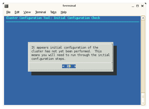
On the cluster configuration tool's Initial Configuration Check screen, select OK on the initial window.
Figure 3-4 shows the initial window.
The cluster configuration tool recognizes a configured cluster. If you start the tool on a configured SGI ICE system, it opens into the Main Menu.
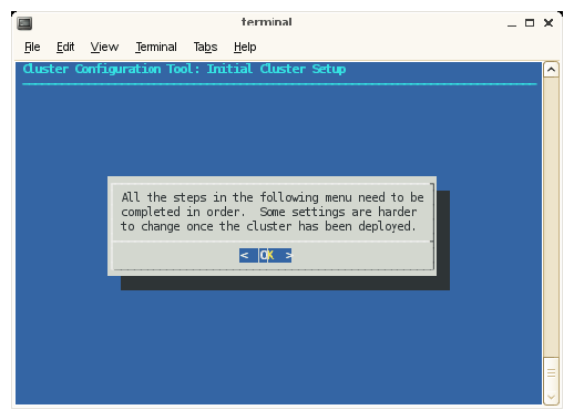
On the Initial Cluster Setup screen, select OK on the screen.
Figure 3-5 shows the window.
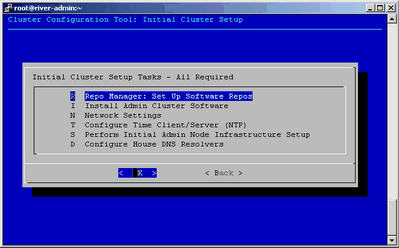
On the Initial Cluster Setup screen, select R Repo Manager: Set Up Software Repos, and click OK.
Figure 3-6 shows the Initial Cluster Setup screen with the task menu. This procedure guides you through the tasks you need to perform for each of the menu selections on the Initial Cluster Setup screen.
The next few steps create software repositories for the initial installation packages and for updates. You need to create repositories for the following software:
The operating system software, either RHEL or SLES
SGI Foundation Software
SGI Management Center
(Optional) SGI Performance Suite
The menu system prompts you to insert hard media or specify a path for some of the preceding software, so locate your system disks before you proceed.
On the One or more ISOs were embedded on the ... screen, select Yes.
On the Repositories are created ... screen, press Enter.
On the You will now be prompted to add additional media ... screen, select OK.
On the Would you like to register media with Tempo? ... screen, select Yes.
On the Please either insert the media in your DVD drive ... screen, select either Insert DVD or Use Custom path/url.
Proceed as follows:
To install the software from DVDs, perform the following steps:
Insert a DVD.
Select Mount inserted DVD.
On the Media registered successfully with crepo ... screen, select OK, and eject the DVD.
On the Would you like to register media with Tempo? ... screen, select Yes if you have more software that you need to register.
If you select Yes, repeat the preceding tasks in this sequence for the next DVD.
If you select No, proceed to the next step.
To install the software from a network location, perform the following steps:
Select Use custom path/URL.
On the Please enter the full path to the mount point or the ISO file ... screen, type the full path in server_name: path_name/iso_file format. This field also accepts a URL or an NFS path. Select OK after typing the path.
On the Media registered successfully with crepo ... screen, select OK.
On the Would you like to register media with Tempo? ... screen, select Yes if you have more software that you need to register.
If you select Yes, repeat the preceding tasks in this sequence for the next DVD.
If you select No, proceed to the next step.
Repeat the following steps until all software is installed:
If you plan to configure SGI MPT and run SGI MPT programs, make sure to install SGI-Accelerate and SGI-MPI from the SGI Performance Suite.
On the Initial Cluster Setup Tasks screen, select I Install Admin Cluster Software, and select OK.
This step installs the cluster software that you wrote to the repositories.
On the Initial Cluster Setup Tasks screen, select N Network Settings, and select OK.
(Conditional) Create a routed management network.
Complete this step if you have at least 300-500 flat compute nodes in your cluster. If you have more than 500 flat compute nodes, consider creating more than one routed management network.
Complete the following steps:
On the Cluster Network Settings screen, select A Add Subnet, and select OK
On the Select network type screen, press the space bar to move the asterisk (*) up to the first line. This action selects the upper line, and the line now looks like this:
(*) 1 mgmt/mgmt-bmc
Select OK.
On the Insert network name, subnet, netmask, bmc subnet and bmc network screen, type in the information to define the routed management network. Use the arrow keys to move from field to field on this screen. The information you need to enter is as follows:
Field name Information
name A unique name for this network. For example, head2.
subnet The network IP address (start of the range) for the nodes on the routed management network.
netmask The network mask for the nodes on routed management network.
bmc subnet The network IP address (start of the range) for the node BMCs on the routed management network.
bmc netmask The network mask for the node BMCs on the routed management network.
On the Network name ... screen, verify that this is the information you specified for the routed management network, and select OK.
On the Network name -bmc ... screen, verify that this is the information you specified for the node BMC network, and select OK.
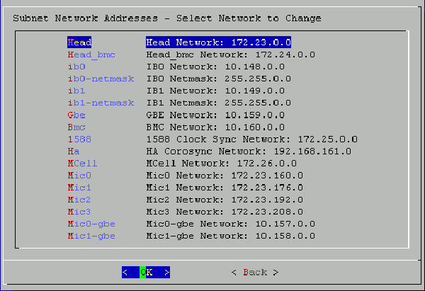
On the Cluster Network Settings screen, select S List and Adjust Subnet Addresses, and select OK.
On the Warning: Changing the subnet IP addresses ... screen, click OK.
Review the settings on the Subnet Network Addresses screen, and modify these settings only if absolutely necessary.
Figure 3-7 shows the Subnet Network Addresses screen. This screen displays the default networks and netmasks that reside within the cluster.
If you accept the defaults, select OK.
If you do not accept the defaults, you can change the network settings. For example, it is possible that your site has existing networks or conflicting network requirements. For additional information about the IP address ranges, see Appendix B, “Subnetwork Information”. Complete the following steps if you need to change the network settings:
Highlight the setting you want to change, and select OK.
Type in a new IP address, and select OK.
Press Enter.
On the Update Subnet Addresses screen, the Head Network field shows the admin node's IP address. SGI recommends that you do not change the IP address of the admin node or rack leader controllers (RLCs) if at all possible. You can change the IP addresses of the InfiniBand network (IB0 and IB1) to match the IP requirements of the house network, and then select OK.
On the Cluster Network Settings screen, select D Configure Cluster Domain Name, and select OK.
On the Please enter the domain name for this cluster pop-up window, type the domain name, and select OK.
The domain you type becomes a subdomain to your house network.
For example, type ice.americas.sgi.com.
On the Cluster Network Settings screen, select Back.
On the Initial Cluster Setup screen, select T Configure Time Client/Server (NTP), and select OK.
Configure your NTP server.
On the subsequent screens, you set the admin node as the time server to the cluster. For this step, the installer screens differ on RHEL platforms and SLES platforms.
On RHEL platforms, complete the following step:
On the A new ntp.conf has been put in to position ... screen, select OK.
On SLES platforms, complete the following steps:
On the A new ntp.conf has been put in to position ... screen, select OK.
Use the YAST interface and the SLES documentation to guide you through the NTP configuration.
On the This procedure will replace your ntp configuration file ... screen, select Yes.
On the Initial Cluster Setup Tasks menu, select S Perform Initial Admin Node Infrastructure Setup , and select OK.
On the A script will now perform the initial cluster ... screen, select OK.
This step runs a series of scripts that configure the admin node. The scripts also create the root images for the RLCs, SGI ICE compute nodes, and flat compute nodes. The scripts run for approximately 30 minutes. At the end, the script issues a line that includes install-cluster completed in its output.
The final output of the script is as follows:
/opt/sgi/sbin/create-default-sgi-images Done!
The output of the mksiimage commands are stored in a log file at the following location:
/var/log/cinstallman
On the Initial Cluster Setup Complete window, select OK.
On the One or more ISOs were embedded on the admin install DVD and copied to ..., screen, select OK.
Depending on what you have installed, this screen might not appear.
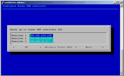
On the Initial Cluster Setup menu, select D Configure House DNS Resolvers, and select OK.
Figure 3-8 shows the Configure House DNS Resolvers screen.
The system autopopulates the values on the Configure House DNS Resolvers screen to match the DNS specifications on the admin node. The DNS resolvers you specify here enable the flat compute nodes to resolve host names on your network. You can set the DNS resolvers to the same name servers used on the admin node itself.
Perform one of the following actions:
To accept these settings, select OK, and then select Yes.
To change the settings, type in different IP addresses, select OK, and then select Yes.
To disable house network resolvers, select Disable House DNS.
On the Setting DNS Forwarders to ... screen, select Yes.
On the Initial Cluster Setup screen, select Back.
This action returns you to the cluster configuration tool main menu.
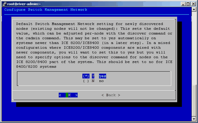
On the Main Menu, select S Configure Switch Management Network (optional), and select OK.
The switch management network enables the Ethernet switch to control all VLANs and trunking.
On the pop-up window that appears, make sure that Y yes is selected, and select OK.
Figure 3-9 shows the selection pop-up window:
(Conditional) On the Main Menu, select N Configure MCell Network (optional), and select OK.
Complete this step if your SGI ICE system contains MCells.
(Conditional) On the screen that appears, select Y yes, and select OK.
Complete this step if your SGI ICE system contains MCells.
Select Quit.
Type the cattr list -g command to verify the features you configured with the cluster configuration tool.
Example: The following output is generated on an SGI ICE cluster with MCells. If your system does not include MCells, the mcell_network value should display no. The output is as follows:
# cattr list -g
global
  cluster_domain          : smc.americas.sgi.com
  tempo_dhcp_option       : 149
  head_vlan               : 1
  mcell_vlan              : 3
  rack_vlan_start         : 101
  rack_vlan_end           : 1100
  mgmt_vlan_start         : 2001
  mgmt_vlan_end           : 2500
  redundant_mgmt_network  : yes
  switch_mgmt_network     : yes
  mcell_network           : yes
  discover_skip_switchconfig : no
  max_rack_irus           : 4
  mic                     : 0
  blademond_scan_interval : 120
  dhcp_bootfile           : grub2
  udpcast_min_receivers   : 1
  udpcast_min_wait        : 10
  udpcast_max_wait        : 10
  udpcast_max_bitrate     : 900m
  udpcast_rexmit_hello_interval : 0
  udpcast_mcast_rdv_addr  : 224.0.0.1
  my_sql_replication      : yes
  conserver_logging       : yes
  conserver_ondemand      : no
  edns_udp_size           : 512
  replication_file        : mysql-bin.000005
  replication_position    : 9103
Note: On an SGI Rackable cluster, the cattr output is similar to the preceding example output, but the output contains fewer fields. If you need to respecify any global values, start the cluster configuration tool again, and correct your specifications. To start the cluster configuration tool, type the following command:
# /opt/sgi/sbin/configure-cluster
Proceed to one of the following:
To configure one or more external Domain Name Service (DNS) servers, proceed to “(Conditional) Configuring External Domain Name Service (DNS) Servers ”.
To synchronize the software repository, install updates, and clone the images, proceed to “Synchronizing the Software Repository, Installing Software Updates, and Cloning the Images”.
Perform the procedure in this section if you want to enable network address translation (NAT) gateways for the cluster. A later procedure explains how to configure NAT as a service on a flat compute node. If you want to enable NAT, perform the procedure in this topic at this time.
When external DNS and NAT are enabled, the host names for the SGI ICE compute nodes (blades) in the cluster resolve through external DNS servers. The SGI ICE compute nodes need to be able to reach your house network.
| Note: You cannot configure this feature after you run the discover command. If you attempt to configure this feature after you run the discover command, the IP addresses assigned previously on the configured nodes remain. |
The following procedure explains how to configure external DNS servers.
Procedure 3-11. To configure external DNS servers
Obtain a large block of IP addresses from your network administrator.
This feature requires you to reserve a block of IP addresses on your house network. If you want to use external DNS servers, all nodes on the InfiniBand networks, both the ib0 and ib1 networks are included. The external DNS is enabled to provide addresses for all rack leader controllers (RLCs), all SGI ICE compute nodes, and all flat compute nodes.
Through an ssh connection, log into the admin node as the root user.
Type the following command to start the cluster configuration tool:
# /opt/sgi/sbin/configure-cluster
Select E Configure External DNS Masters (optional) , and select OK.
On the This option configures SGI Tempo to look up the IP addresses for the InfiniBand networks from external DNS servers ... screen, select Yes.
On the Enter up to five external DNS master IPs screen, type the IP addresses of up to five external DNS servers on your house network, and select OK.
On the Setting external DNS masters to ip_addr, select Yes.
Proceed to “Synchronizing the Software Repository, Installing Software Updates, and Cloning the Images”.
The following procedure explains how to update the software in the repositories that you created with the cluster configuration tool. The following procedure assumes that the cluster has a connection to the internet. If you need to perform this procedure on a secure cluster, you need to modify this procedure. For a secure system, obtain the software updates from SGI Supportfolio manually and use the crepo command to install the software manually.
Procedure 3-12. To update the software
Through an ssh connection, log into the admin node as the root user.
Type the following command to retrieve information about the network interface card (NIC) bonding method on the admin node:
# cadmin --show-mgmt-bonding --node admin
If bonding has been set appropriately, the command returns 802.3ad.
If the command does not return 802.3ad, type the following commands to set the bonding appropriately and reboot the system:
# cadmin -set-mgmt-bonding -node admin 802.3ad
# reboot
Type the following command to retrieve the new images from SGI SupportFolio and the operating system vendor:
# sync-repo-updates
For RHEL-based systems, make sure the system is subscribed as rhel-x86_64-server-6.
This step requires that the system be connected to the internet. Contact your SGI representative if this update method is not acceptable for your site.
Type the cinstallman --show-images command to retrieve the image names.
For example:
# cinstallman --show-images
Image Name               BT VCS Compat_Distro
ice-rhel6.6              1  1   rhel6
        2.6.32-504.el6.x86_64
rhel6.6                  0  1   rhel6
        2.6.32-504.el6.x86_64
lead-rhel6.6             0  1   rhel6
        2.6.32-504.el6.x86_64
The preceding output includes a line for the MPSS images if you downloaded MPSS software for Intel Many Integrated Core Architecture (Intel MIC Architecture) based products and created an image.
(Optional) Clone the images.
Complete this step if you want to back up the current images before they are installed.
Type the following command:
cinstallman --create-image --clone --source src_image_name --image image
For src_image_name, specify the name of the source image. For example: lead-rhel6.6.
For image, specify a file name for the copied file (the clone). For example: lead-rhel6.6.backup
Example 1: The following commands create backup copies of the current installation images:
# cinstallman --create-image --clone --source ice-compute-rhel6.6 --image ice-compute-rhel6.6.backup
# cinstallman --create-image --clone --source rhel6.6 --image rhel6.6.backup
# cinstallman --create-image --clone --source lead-rhel6.6 --image lead-rhel6.6.backup
Example 2: In this example, the commands create backup copies of the current installation images and tag the backup copies as source-controlled copies. The commands assume that there are multiple versions of the source image that exist at this time. The commands copy revision 2 of the source image to the backup.
# cinstallman --create-image --clone --source ice-compute-rhel6.6 --rev 2 --image ice-compute-rhel6.6.backup
# cinstallman --create-image --clone --source rhel6.6 --rev 2 --image rhel6.6.backup
# cinstallman --create-image --clone --source lead-rhel6.6 --rev 2 --image lead-rhel6.6.backup
Type a series of cinstallman --update-image commands to install the software images on the nodes.
For each image, specify the software package you want to install on each type of node.
For example, to install the packages shown in Step 4, type the following commands:
# cinstallman --update-image --image ice-compute-rhel6.6
# cinstallman --update-image --image rhel6.6
# cinstallman --update-image --image lead-rhel6.6
Proceed to one of the following:
If your cluster contains Intel® Many Integrated Core Architecture (Intel MIC Architecture) devices, proceed to “(Conditional) Downloading the Intel Manycore Platform Software Stack (MPSS) Software and Creating Images”.
If your cluster does not contain MIC devices, proceed to “Configuring the Switches”.
Perform the procedures in this topic if nodes in your cluster are equipped with Intel Many Integrated Core Architecture (Intel MIC Architecture) based products. The Intel Many Integrated Core (MIC) devices are part of the Intel Manycore Platform Software Stack that runs on the Intel Xeon Phi Coprocessors found on SGI ICE compute nodes and flat compute nodes.
Intel Corporation provides software for its Intel MIC architecture products, and you need to download this software for use on your SGI cluster. The MPSS package that you download contains the software packages for the MIC devices on the SGI cluster nodes. The procedures in this topic explain how to download the RPMs from the Intel Corporation website and how to create images for the nodes that are equipped with MIC devices.
Your system might have MIC devices on SGI ICE compute nodes, on the flat compute nodes, or both. If your cluster is equipped with MIC devices, each compute blade includes one or two IP addresses for each device. Only one cable connects each compute blade to the network, but each MIC device requires its own, unique IP address on your network.
Complete the procedures that are appropriate for your hardware configuration.
The following procedures explain how to obtain and deploy the MPSS software from Intel Corporation:
Complete the procedure in this topic if you have any MIC devices on your cluster.
The following procedure explains how to download the MPSS software from Intel Corporation.
Procedure 3-13. To download the MPSS package
Open a browser, and navigate to the following website:
Click the Tools & Downloads tab.
Click the Software Drivers: Intel Manycore Platform Software Stack (Intel MPSS) link.
Follow the instructions on the website to download the Linux software version for your operating system platform. The download comes in the form of a tar(1) file.
Use the instructions from Intel to build the RPM files that you need.
A later procedure explains how to transfer these files to the cluster and build new images.
Plan how to specify the number MIC devices per node to SMC.
The next major task in the installation is creating node images that contain the MPSS software. However, at this time, SGI recommends that you plan how to specify the MIC devices to SMC. The procedure called “Configuring the Switches” is the actual procedure that includes specifying the cluster configuration.
The mic=number parameter specifies the quantity of MIC devices on a node. The minimum number of devices is 1. The maximum number of devices is 16. For example, if the cluster contains four MIC devices per node, specify mic=4 in the parameter string that defines the node.
You can specify this parameter in the cluster definition file (recommended) or on the discover command line, as follows:
The cluster definition file defines characteristics for each cluster node. If you use a cluster definition file, specify a mic= number parameter in the list of parameters for each node.
The discover command accepts node characteristics. If you do not have a cluster definition file, plan to specify the mic=number parameter on the discover command line.
Make sure to specify the correct number of MIC devices. If your cluster definition file contains mic=0, or if you do not specify a mic= parameter on the discover command, SMC assumes that the cluster contains no MIC devices.
Proceed to one of the following topics:
Plan to perform both of the preceding procedures if you have MIC devices on both SGI ICE compute nodes and on flat compute nodes.
The following procedure explains how to create SGI ICE compute node images that include MIC device software.
Procedure 3-14. To create compute node images for SGI ICE compute nodes with MIC devices
On the admin node, use the mkdir(1) command, in the following format, to create a directory for the RPM repository:
mkdir -p /tftpboot/intel/mpss_repository_directory
For mpss_repository_directory, type a name for the directory that is to contain the MPSS repository. For convenience, make sure to include an identifier for the MPSS release level you downloaded.
For example:
# mkdir -p /tftpboot/intel/mpss_u3-2.1.6720-19
Use operating system commands to copy the RPM files you downloaded to the /tftpboot/intel/mpss_repository_directory directory on the admin node.
For example, use cp(1), ftp(1), rsync(1), scp(1), or another method.
(Conditional) Rebuild the MPSS modules.
Complete this step
Use the crepo command, in the following format, to specify a custom repository for the MPSS RPMs:
crepo --add rpm_repo_directory -custom rpm_repo_name
The variables in this command are as follows:
For rpm_repo_directory, specify the full path to the directory that contains the RPM files.
For rpm_repo_name, create a name for the image. You can specify the same name for both rpm_repo_directory and rpm_repo_name. After SMC builds the image, the cinstallman --show-images command returns this label in the Image Name column of its output.
For example:
# crepo --add /tftpboot/intel/mpss_u3-2.1.6720-19 --custom mpss_u3-2.1.6720-19
Type the following command to confirm that the MPSS image is in the correct repository:
# crepo --show
Use the crepo command, in the following format, to add the custom repository to the generated RPM list in /etc/opt/sgi/rpmlists:
crepo --select rpm_repo_name
For rpm_repo_name, create a name for the image. You can specify the same name for both rpm_repo_directory and rpm_repo_name. After SMC builds the image, the cinstallman --show-images command returns this label in the Image Name column of its output. This is the same rpm_repo_name that you specified in the following step:
For example, the following command adds the custom repository and displays the content of the respository:
# crepo --select mpss_u3-2.1.6720-19
Selecting: mpss_u3-2.1.6720-19
Updating: /etc/opt/sgi/rpmlists/generated-ice-rhel6.6.rpmlist
Updating: /etc/opt/sgi/rpmlists/generated-lead-rhel6.6.rpmlist
Updating: /etc/opt/sgi/rpmlists/generated-rhel6.6.rpmlist
Type the following command to confirm that you selected the new repository that contains the MPSS RPMs:
# crepo --show
* mpss_u3-2.1.6720-19 : /tftpboot/intel/mpss_u3-2.1.6720-19
* Red-Hat-Enterprise-Linux-6.6 : /tftpboot/distro/rhel6.6
* SGI-MPI-1.9-rhel6 : /tftpboot/sgi/SGI-MPI-1.9-rhel6
* SGI-Management-Center-3.0-rhel6 : /tftpboot/sgi/SGI-Management-Center-3.0-rhel6
* SGI-Foundation-Software-2.11-rhel6 : /tftpboot/sgi/SGI-Foundation-Software-2.11-rhel6
The asterisk character (*) in column 1 indicates an image that is selected.
Type the following command to display the images that are available for installation on the compute nodes:
# cinstallman --show-images
Image Name               BT VCS Compat_Distro
ice-rhel6.6              1  1   rhel6
        2.6.32-504.el6.x86_64
rhel6.6                  0  1   rhel6
        2.6.32-504.el6.x86_64
lead-rhel6.6             0  1   rhel6
        2.6.32-504.el6.x86_64
Use the cinstallman command, in the following format, to clone the current operating system image:
cinstallman --create-image --clone --source current_image --image new_image
The variables in this command are as follows:
For current_image, type the name of the operating system image you want to use that is on the system right now. Choose one that appears in the output from the from the cinstallman --show-images command in the Image Name list. For example, ice-rhel6.6 .
For new_image, type a new name for the operating system image that is to include the MPSS file RPMs. SGI recommends that you include information in the new name that can enable you to identify this image as the operating system image that includes MPSS software. For example, ice-compute-rhel6.6-mic-6720-19 identifies the new image as a RHEL image that contains a revision of the MPSS MIC software.
For example:
# cinstallman --create-image --clone --source ice-rhel6.6 --image ice-rhel6.6-mic-6720-19
Type the following command to display the images and confirm that the new image appears in the list:
# cinstallman --show-images
Image Name               BT VCS Compat_Distro
lead-rhel6.6             0  1   rhel6
        2.6.32-504.el6.x86_64
rhel6.6                  0  1   rhel6
        2.6.32-504.el6.x86_64
ice-compute-rhel6.6      1  1   rhel6
        2.6.32-504.el6.x86_64
ice-compute-rhel6.6-mic-6720-19  1 1   rhel6
        2.6.32-504.el6.x86_64
Use the cinstallman command, in the following format, to install the sgi-mic-compute package and the MPSS RPMs:
cinstallman --yum-image --image image_name install sgi-mic-compute
For image_name, specify the new_image that you created in the following step:
For example:
# cinstallman --yum-image --image ice-rhel6.6-mic-6720-19 install sgi-mic-compute
(Conditional) Enable the SLES operating system to load the MPSS package.
Complete this step if you are installing the MPSS packages on a SLES platform.
Complete the following steps:
Open file /etc/modprobe.d/unsupported-modules with a text editor.
Add the following line at the end of the file:
allow_unsupported_modules 1
Save and close the file.
Type the following command to display all the images:
# cimage --list-images
image: ice-rhel6.6
     kernel: 2.6.32-358.el6.x86_64
image: ice-rhel6.6-mic-6720-19
     kernel: 2.6.32-358.el6.x86_64
The preceding output shows the newly installed image, ice-rhel6.6-mic-6720-19.
Use the cimage command, in the following format, to set the default image for the compute nodes:
cimage --set-default --file_system ice-rhel6.6-mic-6720-19 kernel
The variables in this command are as follows:
For file_system, type either nfs or tmpfs , according to your site practice.
For kernel, type the kernel associated with the new image, as shown in the output from the cimage --list-images command in the following step:
For example:
# cimage --set-default --tmpfs --ice-rhel6.6-mic-6720-19 2.6.32-358.el6.x86_64
Type the following command to confirm that the new image is the default image:
# cimage --show-default
ice-rhel6.6-stout7-mic-6720-15 2.6.32-358.el6.x86_64 tmpfs
Proceed to one of the following:
If your cluster contains MIC devices on the flat compute nodes, proceed to “Creating Images for the Flat Compute Nodes That Include MIC Devices ”.
If your cluster does not contain MIC devices on the flat compute nodes, proceed to “Configuring the Switches”.
The following procedure explains how to create images for flat compute nodes that include MIC device software.
Procedure 3-15. To create software images for flat compute nodes with MIC devices
On the admin node, use the mkdir(1) command, in the following format, to create a directory for the RPM repository:
mkdir -p /tftpboot/intel/mpss_repository_directory
For mpss_repository_directory, type a name for the directory that is to contain the MPSS repository. For convenience, make sure to include an identifier for the MPSS release level you downloaded.
For example:
# mkdir -p /tftpboot/intel/mpss_u3-2.1.6720-19
Use operating system commands to copy the RPM files you downloaded to the /tftpboot/intel/mpss_repository_directory directory on the admin node.
For example, use cp(1), ftp(1), rsync(1), scp(1), or another method.
(Conditional) Rebuild the MPSS modules.
Complete this step if you are installing a kernel that is updated from your operating system's base kernel.
The Intel Corporation distributes modules that support the RHEL and SLES base distributions. If you are installing an updated kernel, however, you need to rebuild the modules for the updated kernel.
Use an editor to open the following file and follow the instructions from Intel Corporation that are included in the file:
/tftpboot/intel/mpss-version/mpss-version/docs/readme.txt
For version, specify the version that matches your MPSS level.
Use the crepo command, in the following format, to specify a custom repository for the MPSS RPMs:
crepo --add rpm_repo_directory -custom rpm_repo_name
The variables in this command are as follows:
For rpm_repo_directory, specify the full path to the directory that contains the RPM files.
For rpm_repo_name, create a name for the image. You can specify the same name for both rpm_repo_directory and rpm_repo_name.
After SMC builds the image, the cinstallman --show-images command returns this label in the Image Name column of its output.
For example:
# crepo --add /tftpboot/intel/mpss_u3-2.1.6720-19 --custom mpss_u3-2.1.6720-19
Type the following command to confirm that the MPSS image is in the correct repository:
# crepo --show
Use the crepo command, in the following format, to add the custom repository to the generated RPM list in /etc/opt/sgi/rpmlists:
crepo --select rpm_repo_name
For rpm_repo_name, create a name for the image. You can specify the same name for both rpm_repo_directory and rpm_repo_name. After the image is built, the cinstallman --show-images command returns this label in the Image Name column of its output. This is the same rpm_repo_name that you specified in the following step:
For example, the following command adds the custom repository and displays the content of the respository:
# crepo --select mpss_u3-2.1.6720-19
Selecting: mpss_u3-2.1.6720-19
Updating: /etc/opt/sgi/rpmlists/generated-ice-rhel6.6.rpmlist
Updating: /etc/opt/sgi/rpmlists/generated-lead-rhel6.6.rpmlist
Updating: /etc/opt/sgi/rpmlists/generated-rhel6.6.rpmlist
Type the following command to confirm that you selected the new repository that contains the MPSS RPMs:
# crepo --show
* mpss_u3-2.1.6720-19 : /tftpboot/intel/mpss_u3-2.1.6720-19
* Red-Hat-Enterprise-Linux-6.6 : /tftpboot/distro/rhel6.6
* SGI-MPI-1.9-rhel6 : /tftpboot/sgi/SGI-MPI-1.9-rhel6
* SGI-Management-Center-3.0-rhel6 : /tftpboot/sgi/SGI-Management-Center-3.0-rhel6
* SGI-Foundation-Software-2.11-rhel6 : /tftpboot/sgi/SGI-Foundation-Software-2.11-rhel6
The asterisk character (*) in column 1 indicates an image that is selected.
Type the following command to display the images that are available for installation on the flat compute nodes:
# cinstallman --show-images
Image Name               BT VCS Compat_Distro
lead-rhel6.6             0  1   rhel6
        2.6.32-504.el6.x86_64
rhel6.6                  0  1   rhel6
        2.6.32-504.el6.x86_64
ice-compute-rhel6.6      1  1   rhel6
        2.6.32-504.el6.x86_64
Use the cinstallman command, in the following format, to clone the current operating system image:
cinstallman --create-image --clone --source current_image --image new_image
The variables in this command are as follows:
For current_image, type the name of the operating system image you want to use. Choose one that appears in the output from the cinstallman --show-images command in the Image Name list. For example, rhel6.6.
For new_image, type a new name for the operating system image that is to include the MPSS file RPMs. SGI recommends that you include information in the new name that can enable you to identify this image as the operating system image that includes MPSS software. For example, rhel6.6-mic-6720-19 identifies the new image as a RHEL image that contains a revision of the MPSS MIC software.
For example:
# cinstallman --create-image --clone --source rhel6.6 --image rhel6.6-mic-6720-19
Type the following command to display the images and confirm that the new image appears in the list:
# cinstallman --show-images
Image Name               BT VCS Compat_Distro
lead-rhel6.6             0  1   rhel6.6
        2.6.32-504.el6.x86_64
rhel6.6                  0  1   rhel6.6
        2.6.32-504.el6.x86_64
ice-rhel6.6              1  1   rhel6.6
        2.6.32-504.el6.x86_64
rhel6.6-mic-6720-19      1  1   rhel6.6
        2.6.32-504.el6.x86_64
Use the cinstallman command, in the following format, to install the sgi-mic-service package and the MPSS RPMs:
cinstallman --yum-image --image image_name install sgi-mic-service
For image_name, specify the new_image that you created in the following step:
For example:
# cinstallman --yum-image --image rhel6.6-mic-6720-19 install sgi-mic-service
(Conditional) Enable the SLES operating system to load the MPSS package.
Complete this step if you are installing the MPSS packages on a SLES platform.
Complete the following steps:
Open file /etc/modprobe.d/unsupported-modules with a text editor.
Add the following line at the end of the file:
allow_unsupported_modules 1
Save and close the file.
Type the following command to display all the images:
# cimage --list-images
image: ice-rhel6.6
     kernel: 2.6.32-358.el6.x86_64
image: ice-rhel6.6-mic-6720-19
     kernel: 2.6.32-358.el6.x86_64
image: rhel6.6-mic-6720-19
     kernel: 2.6.32-358.el6.x86_64
The preceding output shows the newly installed image, rhel6.6-mic-6720-19.
Use the cimage command, in the following format, to set the default image for the flat compute nodes:
cimage --set-default --file_system rhel6.6-mic-6720-19 kernel
The variables in this command are as follows:
For file_system, type either nfs or tmpfs , according to your site practice.
For kernel, type the kernel associated with the new image, as shown in the output from the cimage --list-images command in the following step:
For example:
# cimage --set-default --tmpfs --rhel6.6-mic-6720-19 2.6.32-358.el6.x86_64
Type the following command to confirm that the new image is the default image:
# cimage --show-default
rhel6.6-stout7-mic-6720-15 2.6.32-358.el6.x86_64 tmpfs
Proceed to one of the following:
If you are installing SMC as part of a migration upgrade from SMC 1.7.5, proceed to the folowing:
“(Conditional) Running the Migration Script and Editing the Cluster Definition File”
If you are installing SMC on a new cluster or as part of a refresh, proceed to the following:
Perform the procedure in this topic only if you are installing the SMC software as part of a migration upgrade from SMC 1.7.5.
You need to use separate migrate-sgi-mc commands to convert each SMC 1.7.5 payload file.
The following procedure explains how to run the migration script.
Procedure 3-16. To run the migration script
On the admin node, type the following command:
# migrate-sgi-mc
When the script runs, it prompts you for the image location and performs the following tasks:
Copies the payloads from the specified location into SMC 3.x environment.
Clean up the image to remove unnecessary packages.
Installs packages required by SMC 3.x.
Registers the new image with the SMC database.
Generates a configuration template, smc.txt, for use with the discover command.
Repeat the preceding step for each payload file that you want to convert.
Open file smc.txt from within a text editor.
File smc.txt is a cluster definition file that you can use as input to the discover command. Read through the instructions in “Configuring the Switches” and familiarize yourself with the content of this generated file. Make sure to edit the file as necessary.
Proceed to the following:
SGI clusters have both management switches and InfiniBand (IB) switches. The individual switches are paired into switch stacks, and there are two switches per stack. In each stack, the top switch is typically the master switch, and the bottom switch is typically the slave switch. Although a switch stack actually includes two switches, most documentation refers to a switch stack as a switch.
An SGI cluster is equipped with the following types of switches:
Spine switches. A spine switch is the primary management switch or the primary IB switch. There is one primary management switch and one primary IB switch.
Leaf switches. A leaf switch is a secondary management switch or a secondary IB switch. There can be many leaf switches configured as part of a cluster system.
The discover command initializes and configures the system components for the cluster. The switch configuration procedures explain how to use the discover command to configure the cluster's management switches first. After you configure the management switches, if you have MCells, you configure the cooling equipment on the MCell network's switch ports.
The cluster configuration requires that the same IP address be assigned to the cluster's head gateway and to the first management switch, usually mgmtswitch0. The procedures in this topic assume that you want to use the default IP address, which is 172.23.255.254, for both components, but the procedures include example commands that show how to configure an alternate IP address.
Proceed to the following to familiarize yourself with the cluster definition file's purpose:
“About the Cluster Definition File”
A cluster definition file specifies media access control (MAC) addresses, IP addresses, node roles, hostnames, and other information for the cluster components. You can specify the cluster definition file as input to the discover command and to the configure-cluster command. Cluster configuration can proceed much more quickly if you have a cluster definition file. Without the file, you need to power cycle each component manually. For new clusters, you can obtain a cluster definition file from your SGI representative. For clusters that are configured with at least one working slot, you can type the following command to generate a cluster configuration file:
discover --show-configfile > file_name |
You can write the cluster definition file to any file_name and store the cluster definition file in any directory.
Example 1. This example cluster definition file is for an SGI ICE cluster that includes one SGI ICE compute rack and several flat compute nodes. The following information highlights some characteristics of this cluster:
The temponame field and the hostname1 field appear in bold print in this example. The temponame field can contain the hostname of the node or it can contain a label for the role of the component in the cluster. The temponame field is used by SMC internal operations and for flat compute nodes is always service followed by a number. The hostname1 field defines the hostname for the component, and it is this hostname that users need to specify when they want to log into the node. For example, if you configure user services on the two of the flat compute nodes in this cluster, users can log into the cluster by logging into n0 or n1.
The flat compute nodes can have any name. This example file uses the default names. This example shows two ranges. One range includes only n0 and n1. The other range starts at n101 and includes n102, n103, and so on.
Note: Not all flat nodes are shown in the example file. This cluster uses a routed management network for its flat compute nodes. There is a network for the nodes themselves and a network for the BMCs on the nodes. These networks are called head2 and head2-bmc, and they are associated with mgmtsw1. In this example, nodes n101 , n102, and so on are on the user-added head2 management network. Nodes n0, n1, and so on are on the default head management network to which the admin node is directly attached.
In this example, mgmtsw1 is the switch that serves the user-added head2 management network.
The file is as follows:
[discover] temponame=r1lead, mgmt_bmc_net_name=head-bmc, mgmt_bmc_net_macs=00:25:90:58:8b:75, mgmt_net_name=head, mgmt_net_macs=00:25:90:58:8a:94/00:25:90:58:8a:95, redundant_mgmt_network=yes, switch_mgmt_network=yes, mic=0, dhcp_bootfile=grub2, conserver_logging=yes, conserver_ondemand=no, console_device=ttyS1 temponame=service0, mgmt_bmc_net_name=head-bmc, mgmt_bmc_net_macs=00:25:90:58:7d:7f, mgmt_net_name=head, mgmt_net_macs=00:25:90:58:7d:32/00:25:90:58:7d:33, hostname1=n0, redundant_mgmt_network=yes, switch_mgmt_network=yes, mic=0, dhcp_bootfile=grub2, conserver_logging=yes, conserver_ondemand=no, root_type=disk, console_device=ttyS1 temponame=service1, mgmt_bmc_net_name=head-bmc, mgmt_bmc_net_macs=00:25:90:58:96:a2, mgmt_net_name=head, mgmt_net_macs=00:25:90:58:96:54/00:25:90:58:96:55, hostname1=n1 redundant_mgmt_network=yes, switch_mgmt_network=yes, mic=0, dhcp_bootfile=grub2, conserver_logging=yes, conserver_ondemand=no, root_type=disk, console_device=ttyS1 temponame=service101, mgmt_bmc_net_name=head2-bmc, mgmt_bmc_net_macs=00:1E:67:2C:53:92, mgmt_net_name=head2, mgmt_net_macs=00:1E:67:2C:53:8E/00:1e:67:2c:53:8f, hostname1=n101, redundant_mgmt_network=yes, switch_mgmt_network=yes, mic=0, dhcp_bootfile=ipxe, conserver_logging=yes, conserver_ondemand=no, root_type=disk, console_device=ttyS0 temponame=service102, mgmt_bmc_net_name=head2-bmc, mgmt_bmc_net_macs=00:1E:67:2C:58:AF, mgmt_net_name=head2, mgmt_net_macs=00:1E:67:2C:58:AB/00:1e:67:2c:58:ac, hostname1=n102, redundant_mgmt_network=yes, switch_mgmt_network=yes, mic=0, dhcp_bootfile=ipxe, conserver_logging=yes, conserver_ondemand=no, root_type=disk, console_device=ttyS0 temponame=service103, mgmt_bmc_net_name=head2-bmc, mgmt_bmc_net_macs=00:1E:67:2C:54:E2, mgmt_net_name=head2, mgmt_net_macs=00:1E:67:2C:54:DE/00:1e:67:2c:54:df, hostname1=n103, redundant_mgmt_network=yes, switch_mgmt_network=yes, mic=0, dhcp_bootfile=ipxe, conserver_logging=yes, conserver_ondemand=no, root_type=disk, console_device=ttyS0 . . . temponame=mgmtsw0, mgmt_net_name=head, mgmt_net_macs=b4:0e:dc:38:6b:17, net=head/head- bmc, ice=yes, type=spine temponame=mgmtsw1, mgmt_net_name=head, mgmt_net_macs=b4:0e:dc:38:6b:18, net=head2/head2- bmc, ice=no, type=leaf [dns] cluster_domain=acme.americas.sgi.com nameserver1=137.38.225.5 nameserver2=137.38.31.248 [attributes] dhcp_bootfile=grub2 udpcast_rexmit_hello_interval=0 udpcast_min_receivers=1 head_vlan=1 mcell_network=yes udpcast_min_wait=10 my_sql_replication=yes redundant_mgmt_network=yes max_rack_irus=16 udpcast_max_bitrate=900m udpcast_max_wait=10 udpcast_mcast_rdv_addr=224.0.0.1 rack_vlan_end=1100 switch_mgmt_network=yes mcell_vlan=3 mic=0 conserver_logging=yes rack_vlan_start=101 conserver_ondemand=no blademond_scan_interval=120 [networks] name=private, subnet=172.26.0.0, netmask=255.255.0.0 name=public, subnet=137.38.82.0, netmask=255.255.255.0, gateway=137.38.82.254 name=head, type=mgmt, vlan=1, subnet=172.23.0.0, netmask=255.255.0.0, gateway=172.23.255.254 name=head-bmc, type=mgmt-bmc, vlan=1, subnet=172.24.0.0, netmask=255.255.0.0 name=mcell-net, type=cooling, subnet=172.26.0.0, netmask=255.255.0.0 name=ha-net, type=ha, subnet=192.168.161.0, netmask=255.255.255.0 name=ib-0, type=ib, subnet=10.148.0.0, netmask=255.255.0.0 name=ib-1, type=ib, subnet=10.149.0.0, netmask=255.255.0.0 name=gbe, type=lead-mgmt, subnet=10.159.0.0, netmask=255.255.0.0, rack_netmask=255.255.252.0 name=bmc, type=lead-bmc, subnet=10.160.0.0, netmask=255.255.0.0, rack_netmask=255.255.252.0 name=head2, type=mgmt, vlan=2001, subnet=172.54.0.0, netmask=255.255.0.0, gateway=172.54.255.254 name=head2-bmc, type=mgmt-bmc, vlan=2001, subnet=172.99.0.0, netmask=255.255.0.0, gateway=172.99.255.254 |
Example 2. This example cluster definition file is for an SGI Rackable cluster with 100 flat compute nodes. For simplicity's sake, the example file shows only two flat compute services nodes and the management switches. The following information highlights some characteristics of this cluster:
The information in the temponame field defines the role for each of the two flat compute nodes in this cluster. The content of the temponame field and the hostname1 field can be identical; in other words, you can use the node's hostname as its temponame.
The content of the temponame field for each flat compute node is servicen, where n is a number from 1 through 101.
The hostname1 field defines the hostname that users need to specify when they want to log into a node. The text in the hostname1 field is the text that appears in the output for most SMC commands when the command generates output.
The cluster definition file specifies a multicast installation that uses udpcast transport for the flat compute nodes, service1 and service101.
The top-level switch, mgmtsw0, is defined as spine switch and serves the head network. Switch mgmtsw1 is defined as a leaf switch and serves the routed management network, head2.
The definition for both switches includes ice=no because this cluster has no SGI ICE components.
The file is as follows:
[discover] temponame=service1, mgmt_bmc_net_name=head-bmc, mgmt_bmc_net_macs=00:25:90:1A:6D:3E, mgmt_net_name=head, mgmt_net_macs=00:25:90:1A:AC:D0/00:25:90:1a:ac:d1, hostname1=mycluster1, redundant_mgmt_network=yes, switch_mgmt_network=yes, mic=0, dhcp_bootfile=grub2, conserver_logging=yes, conserver_ondemand=no, root_type=disk, console_device=ttyS1,transport=udpcast ... temponame=service101, mgmt_bmc_net_name=head2-bmc, mgmt_bmc_net_macs=00:1E:67:2C:53:92, mgmt_net_name=head2, mgmt_net_macs=00:1E:67:2C:53:8E, hostname1=n101, redundant_mgmt_network=yes, switch_mgmt_network=yes, mic=0, dhcp_bootfile=ipxe, conserver_logging=yes, conserver_ondemand=no, root_type=disk, console_device=ttyS0,transport=udpcast temponame=mgmtsw0, mgmt_net_name=head,mgmt_net_macs=00:26:F3:C3:7A:40, net=head/head- bmc, ice=no, type=spine temponame=mgmtsw1, mgmt_net_name=head,mgmt_net_macs=00:04:96:97:C0:78, net=head2/head2-bmc, ice=no, type=leaf [dns] cluster_domain=smc-default.americas.sgi.com nameserver1=128.162.236.210 nameserver2=128.162.236.211 nameserver3=198.149.32.11 [attributes] dhcp_bootfile=grub2 udpcast_min_receivers=1 head_vlan=1 mcell_network=yes udpcast_min_wait=10 my_sql_replication=yes redundant_mgmt_network=yes max_rack_irus=16 udpcast_max_bitrate=900m udpcast_max_wait=10 rack_vlan_end=1100 switch_mgmt_network=yes mcell_vlan=3 mic=0 conserver_logging=yes rack_vlan_start=101 conserver_ondemand=no blademond_scan_interval=120 [networks] name=private, subnet=172.26.0.0, netmask=255.255.0.0 name=public, subnet=128.162.243.0, netmask=255.255.255.0, gateway=128.162.243.1 name=head, type=mgmt, vlan=1, subnet=172.23.0.0, netmask=255.255.0.0, gateway=172.23.255.254 name=head-bmc, type=mgmt-bmc, vlan=1, subnet=172.24.0.0, netmask=255.255.0.0 name=mcell-net, type=cooling, subnet=172.26.0.0, netmask=255.255.0.0 name=ha-net, type=ha, subnet=192.168.161.0, netmask=255.255.255.0 name=ib-0, type=ib, subnet=10.148.0.0, netmask=255.255.0.0 name=ib-1, type=ib, subnet=10.149.0.0, netmask=255.255.0.0 name=gbe, type=lead-mgmt, subnet=10.159.0.0, netmask=255.255.0.0, rack_netmask=255.255.252.0 name=bmc, type=lead-bmc, subnet=10.160.0.0, netmask=255.255.0.0, rack_netmask=255.255.252.0 name=head2, type=mgmt, vlan=2001, subnet=172.98.0.0, netmask=255.255.0.0, gateway=172.98.255.254 name=head2-bmc, type=mgmt-bmc, vlan=2001, subnet=172.99.0.0, netmask=255.255.0.0, gateway=172.99.255.254 |
The following list explains the procedures you need to follow to configure the switches:
| Procedure | Circumstance |
| “Verifying the Switch Cabling” | All switch configuration circumstances. Perform this procedure regardless of the presence of a cluster definition file or MCells. |
| “Configuring Management Switches With a Cluster Definition File ” | If you have a cluster definition file. |
| “Configuring Management Switches Without a Cluster Definition File ” | If you do not have a cluster definition file. |
| “(Conditional) Configuring the Cooling Racks and Cooling Distribution Units (CDUs) on the MCell Network's Switch Ports” | (Conditional) If you have MCells. This extra procedure configures the MCell switches separately from the rest of the cluster switches. |
The following figures show example switch cabling. Depending on the switch configuration procedure you use, you might have to plug cables out from and into switch ports during the configuration process. Regardless of the procedure you use, the cables on your switches eventually become cabled as shown in the following figures.
Figure 3-10 shows a switch stack with two switches. In this switch stack, the two switches constitute the spine switch stack. One is the master switch and the other is the slave switch.
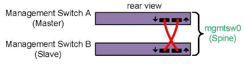
Figure 3-11 shows a switch stack with multiple switches. The first two switches constitute the spine switch stack, and the other switches constitute the secondary switch stack.
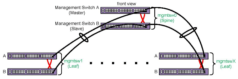
The following procedure explains how to inspect your switches and prepare for the configuration procedure.
Procedure 3-17. To verify your switches
Visually inspect your system.
Note the types of switches you have and their identifiers. At a minimum, you have one spine switch stack. The admin node connects to the master switch in the spine switch stack. You might have additional leaf switch stacks.
Within each stack, each switch is labeled MSW xx. In the spine switch stack, the master switch is labeled MSW0A, and the slave switch is labeled MSW0B. In the first leaf switch stack, the master switch is labeled MSW1A, and the slave switch is labeled MSW1B. The A and B on the switch labels identify the master switch and slave switch in the stack. The switchconfig set command operates on a switch stack (not just one switch), so you need to note only the characters on the label that precede the A and B when you provide information to the switchconfig set command. Use the following table to determine the value you need to use for switch on the switchconfig commands:
switch Label
mgmtsw0 MSW0A or MSW0B
mgmtsw1 MSW1A or MSW1B
mgmtsw2 MSW2A or MSW2B
mgmtsw3 MSW3A or MSW3B
mgmtsw4 MSW4A or MSW4B
mgmtsw5 MSW5A or MSW5B
mgmtsw6 MSW6A or MSW6B
mgmtsw7 MSW7A or MSW7B
mgmtsw8 MSW8A or MSW8B
mgmtsw9 MSW9A or MSW9B
Make sure that only the admin node is plugged in and that all rack circuit breakers are powered off.
If you have a cluster definition file, connect all other nodes and switches to a power source, but do not power them on. That is, make sure that all chassis management controllers (CMCs) on the rack leader controllers (RLCs), all RLCs, all SGI ICE compute nodes, all flat compute nodes, all switches, and so on, are not powered on.
If you do not have a cluster definition file, unplug all nodes and switches other than the admin node. The admin node should be the only component that is plugged in.
(Conditional) Remove the cascade cables that connect the slaves switches together.
Complete this step only if you have two or more switch stacks.
Locate the cascading cables that connect the switch stacks to each other, and unplug the cascading cable end from the lower switch in the neighboring switch stack. On the front of the switch stack, unplug the cascading cables that plug into the ports on the slave switches. When you unplug one end of each cable, you prevent a switching loop.
Note: Do not unplug the stacking cables in the rear of the switch stack. The installation procedure instructs you to plug or unplug only the cascading cables in the front of the switch stack. For example, if you have one leaf switch stack, locate the cascading cable that runs from the slave switch on the spine switch to the slave switch on the leaf switch. Unplug that cable from the port on the slave switch.
Proceed as follows:
If you have a cluster definition file, proceed to the following:
“Configuring Management Switches With a Cluster Definition File ”
If you do not have a cluster definition file, proceed to the following:
“Configuring Management Switches Without a Cluster Definition File ”
The following procedure explains how to configure your switches when you have each switch's MAC information in a cluster definition file.
Procedure 3-18. To configure switches -- with a cluster definition file
Through an ssh connection, log in as root to the admin node, and write the cluster definition file to a location on the admin node.
For example, write it to /var/tmp/config_file.
Plug in all the switches.
(Conditional) Specify a site-specific IP address for the head gateway.
Complete this step if you need to set a site-specific, nondefault IP address for the spine switch stack (head gateway).
By default, SGI sets the IP address for the spine switch stack (head gateway) to 172.23.0.254. Type the cadmin command in the following format to set a site-specific IP address:
cadmin -set-head-gateway IP_addr
For IP_addr, specify your site-specific IP address.
Use the discover command, in the following format, to configure the spine switch stack (the switches labeled MSW0A and MSW0B), which is attached to the admin node:
discover --mgmtswitch 0 --configfile path
For path, type the full path to the location of the cluster definition file.
For example:
# discover --mgmtswitch 0 --configfile /var/tmp/config_file
This step assigns an IP address to the spine switch stack. The spine switch stack becomes the head gateway.
(Conditional) Type additional discover commands for each secondary switch stack.
Complete this step if you have more than one switch.
The formats for these additional commands are as follows:
discover --mgmtswitch num --configfile path
The arguments are as follows:
Argument Specification
num The identifier for the switch stack.
path The full path to the location of the cluster definition file.
For example:
# discover --mgmtswitch 1 --configfile /var/tmp/mac_file
(Conditional) On the front of the switch stack, plug the cascading cables into the ports on the slave switches.
Complete this step only if you have two or more switch stacks.
This step is the opposite of the following step, in which you unplugged the cascading cables from the ports on the slave switches:
Type the following command to retrieve information about the switches that you discovered, and examine the output for errors:
# cnodes --mgmt-switch
Use the ssh(1) command to open a console window to the admin node.
Type the following command, and monitor the power-on process in the admin node's console window:
# tail -f /var/log/cmcdetectd.log
Flip the power breakers on the cluster's CMCs, one rack at a time.
The cmcdetectd daemon runs on the admin node. It configures the top level switches so that the CMCs are on the appropriate rack VLAN. After you power on rack one, the cmcdetectd daemon detects the rack and adds the rack to the switch. After the CMCs for rack one appear on the switch, power on the CMCs for rack two.
Use the switchconfig command, in the following format, to list the CMCs associated with each switch:
switchconfig list -s switch
For switch, specify the system ID for a switch, for example mgmtsw0, mgmtsw1, and so on.
Issue one of these commands for each switch in your configuration and examine the output. If the output includes all the CMCs in your SGI ICE system, you can proceed with your configuration. If the output contains errors or does not include all expected CMCs, contact your SGI representative for troubleshooting information.
Save the configuration to the nonvolatile memory (flash) on the switches.
Note: This step is very important. In the event of a power outage or other interruption, the switch stack boots with the saved configuration. Type the switchconfig command in the following format:
switchconfig save_running_config -s mgmtsw0[,mgmtsw1,mgmtsw2,...]
Include the parameters mgmtsw1, mgmtsw2 , and so on, only if there are switches in addition to the spine switch (mgmtsw0).
Use the switchconfig command, in the following format, to back up the switch configuration to a file on the admin node:
switchconfig pull_switch_config -s switch_ID -f file [--debug]
The arguments are as follows:
Argument Specification
switch_ID The switch system ID. For example, this could be mgmtsw0, mgmtsw1, mgmtsw2 , and so on. The output from the cnodes command includes this information.
file The name of the file to receive the switch configuration information. The command writes the file to the /tftpboot/ file.cfg. If your file specification ends in .cfg, the command does not append another .cfg string to the file name.
The --debug parameter is optional. When specified, the command writes debugging information to /var/log/switchconfig .
For example, the following command writes the configuration file for mgmtsw0 to file /tftpboot/mgmtsw0_startup1.cfg on the admin node:
# switchconfig pull_switch_config -s mgmtsw0 -f mgmtsw0_startup1 --debug
Issue one of these commands per switch.
In the future, if you need to replace the switch, you can save configuration time if you push out this configuration file from the admin node to the new switch.
After all management switches have been configured, proceed as follows::
If you have MCells, proceed to the following:
If you do not have MCells, proceed to the following:
The following procedure explains how to configure your switches when you do not have the switch information in a cluster definition file.
Procedure 3-19. To configure switches -- without a cluster definition file
Through an ssh connection, log in to the admin node as the root user.
(Conditional) Specify a site-specific IP address for the head gateway.
Complete this step if you need to set a site-specific, nondefault IP address for the spine switch stack (head gateway).
By default, SGI sets the IP address for the spine switch stack (head gateway) to 172.23.0.254. Type the following command to set a site-specific IP address:
cadmin -set-head-gateway IP_addr
For IP_addr, specify your site-specific IP address.
Type the discover command in one of the following formats to configure the spine switch:
On SGI ICE platforms, type the following discover command:
# discover --mgmtswitch 0,ice=yes,type=spine
On SGI Rackable platforms, type the following discover command:
# discover --mgmtswitch 0,ice=no,type=spine
Notes:
When you specify the ice=yes parameter, you indicate to the discover command that the cluster includes rack leader controllers and is, therefore, an SGI ICE cluster.
The type=type parameter specifies whether the switch being configured is the spine switch or one of the leaf switches. If you do not specify a type parameter, and you are configuring a management switch, the discover command uses the link layer discovery protocol (LLDP) to attempt to determine the switch that is directly connected to the admin node.
When prompted, connect the spine switch stack to a power source.
To complete this step, plug in the master switch and then the slave switch so that the entire spine switch stack is powered up. In this way, the master switch boots just a few seconds before the slave switch.
The discover command configures the MAC address of the switch after you connect the spine switch stack to a power source.
(Conditional) Plug in the switch when prompted, and type a discover command to configure each leaf switch stack.
Complete this step if you have leaf switch stacks.
Complete the following steps:
a. Plug in the switch stack when the system prompts you to do so.
b. Type a discover command, in the following format, for your platform::
On SGI ICE platforms, type one or more discover commands in the following format:
# discover --mgmtswitch num,ice=yes,type=leaf
For num, type the identifier for the switch.
For example:
# discover --mgmtswitch 1,ice=yes,type=leaf
On SGI Rackable platforms, type one or more discover commands in the following format:
# discover --mgmtswitch num,ice=no,type=leaf
For num, type the identifier for the switch.
For example:
# discover --mgmtswitch 1,ice=no,type=leaf
(Conditional) On the front of the switch stack, plug the cascading cables into the ports on the slave switches.
Complete this step only if you have leaf switch stacks.
This step is the opposite of the following step, in which you unplugged the cascading cables from the ports on the slave switches:
Type the following command to retrieve information about the switches that you configured, and examine the output for errors:
# cnodes --mgmtswitch
Use the ssh(1) command to open a console window to the admin node.
Type the following command, and monitor the power-on process in the admin node's console window:
# tail -f /var/log/cmcdetectd.log
(SGI ICE clusters only) Flip the power breakers on the cluster's CMCs, one rack at a time.
The cmcdetectd daemon runs on the admin node. It configures the top level switches so that the CMCs are on the appropriate rack VLAN. After you power on rack one, the cmcdetectd daemon detects the rack and adds the rack to the switch. After the CMCs for rack one appear on the switch, power on the CMCs for rack two.
(SGI ICE clusters only) Use the switchconfig command, in the following format, to list the CMCs associated with each switch:
switchconfig list -s switch
For switch, specify the system ID for a switch, for example mgmtsw0, mgmtsw1, and so on.
Issue one of these commands for each switch in your configuration and examine the output. If the output includes all the CMCs in your cluster, you can proceed with your configuration. If the output contains errors or does not include all expected CMCs, contact your SGI representative for troubleshooting information.
Save the configuration to the nonvolatile memory (flash) on the switches.
Note: This step is very important. In the event of a power outage or other interruption, the switch stack boots with the saved configuration. Type the switchconfig command in the following format:
# switchconfig save_running_config -s mgmtsw0[,mgmtsw1,mgmtsw2,...]
Include the parameters mgmtsw1, mgmtsw2 , and so on, only if there are switches in addition to the spine switch (mgmtsw0).
For each switch you configured, use the switchconfig command, in the following format, to back up the switch configuration to a file on the admin node:
switchconfig pull_switch_config -s switch_ID -f file [--debug]
The arguments are as follows:
Argument Specification
switch_ID The switch system ID. For example, this could be mgmtsw0, mgmtsw1, mgmtsw2 , and so on. The output from the cnodes command includes this information.
file The name of the file to receive the switch configuration information. The command writes the file to the /tftpboot/ file.cfg. If your file specification ends in .cfg, the command does not append another .cfg string to the file name.
The --debug parameter is optional. When specified, the command writes debugging information to /var/log/switchconfig .
For example, the following command writes the configuration file for mgmtsw0 to file /tftpboot/mgmtsw0_startup1.cfg on the admin node:
switchconfig pull_switch_config -s mgmtsw0 -f mgmtsw0_startup1 --debug
Issue one of these commands per switch.
In the future, if you need to replace a switch, you can save configuration time if you push out this configuration file from the admin node to the new switch.
Use the discover command, in the following format, to save the MAC addresses to a cluster definition file:
# discover --show-configfile > path
For path, type the full path to the location of the cluster definition file. For example, /var/tmp/mac_file .
You can use this cluster definition file if you ever have to configure the switches again.
After all management switches have been configured, proceed as follows:
If you have MCells, proceed to the following:
If you do not have MCells, proceed to the following:
Perform the procedure in this topic if you have an SGI ICE cluster that includes MCells.
A cluster contains CDUs and cooling rack controllers (CRCs). The CDUs and CRCs have statically assigned IP addresses. These IP addresses are critical to associating the individual rack units (IRUs) with specific CDUs or CRCs. For information about these IP addresses, see the following:
Appendix C, “SGI ICE MCell Network IP Addresses”
The following procedure explains how to configure the switches attached to the MCells.
Procedure 3-20. To configure MCell switches
Gather information about the MCell switches in your cluster.
Visually inspect your system. Note the switches identifiers, and note the port identifiers.
Log in as the root user to the admin node.
Type following command to retrieve information about the virtual local area networks (VLANs) that are configured at this time:
# cattr list -g mcell_vlan
global
  mcell_vlan              : 3
The preceding output shows that the MCell VLAN is VLAN 3.
Use the switchconfig set command, in the following format, to configure the ports on which the CDUs and the CRCs are connected to the MCells:
switchconfig set -b none -d vlan_num -p ports -s switch
Type an individual switchconfig set command for each switch on the cluster network.
The arguments are as follows:
Argument Specification
vlan_num The VLAN number of the MCell network. For vlan_num, use the output from the cattr list command as shown earlier in this procedure. The default is 3, and SGI recommends that you do not change this value. This argument appears in two places in the switchconfig command.
ports Specify the target ports. The command configures both the target ports and the corresponding redundant ports.
switch The ID number of the management switch to which the CDU or CDC is attached. For example: mgmtsw0.
To determine this value, you need to visually inspect the switch, as follows:
Locate each CDU or CDC. The following are example labels for CDUs: DU01, DU02, and so on.
Follow the cable that connects each CDU or CDC to a switch. The following is an example label for a cable that connects each CDU to a switch: DU01-LAN1 | 101MSW0A-36.
Note the label on the switch. Make sure that the labels on the cables correspond to the labels on the switch ports.
Example 1. The following command configures VLAN 3 on management switch 0 for target ports 1/31, 1/32, and 1/33 and for redundant ports 2/31, 2/32, and 2/33:
switchconfig set -b none -d 3 -p 1/31,1/32,1/33 -s mgmtsw0
Example 2. The following command configures VLAN 3 on management switch 0 for target ports 2/31, 2/32, and 2/33 and for redundant ports 1/31, 1/32, and 1/33:
switchconfig set -b none -d 3 -p 2/31,2/32,2/33 -s mgmtsw0
Note: If you make a mistake in your configuration, you can disable the ports from the VLANs you configured. The following example command removes the configuration of VLAN 3 from the target ports and the redundant ports: switchconfig unset -p 1/31,1/32,1/33 -s mgmtsw0
Repeat the following step for each CDU and each CRC attached to your system:
If you encounter errors, issue a switchconfig set command again.
Save the configuration to the nonvolatile memory (flash) on the switches.
Note: This step is very important. In the event of a power outage or other interruption, the switch stack boots with the saved configuration. Type the switchconfig command in the following format:
switchconfig save_running_config -s mgmtsw0[,mgmtsw1,mgmtsw2,...]
Include the parameters mgmtsw1, mgmtsw2 , and so on, only if there are switches in addition to the spine switch (mgmtsw0).
Type the following command to back up the switch configuration to a file on the admin node:
switchconfig pull_switch_config -s switch_ID -f file
The arguments are as follows:
Argument Specification
switch_ID The switch system ID. For example, this could be mgmtsw0, mgmtsw1, mgmtsw2 , and so on. The output from the cnodes command includes this information.
file The name of the file to receive the switch configuration information. The command writes the file to the /tftpboot/ file.cfg. If your file specification ends in .cfg, the command does not append another .cfg string to the file name.
For example, the following command writes the configuration file for mgmtsw0 to file /tftpboot/mgmtsw0_startup1.cfg on the admin node:
switchconfig pull_switch_config -s mgmtsw0 -f mgmtsw0_startup1 [--debug]
The --debug parameter is optional. When specified, the command writes debugging information to /var/log/switchconfig .
In the future, if you need to replace the switch, you can save configuration time if you push out this configuration file from the admin node to the new switch.
After all switches have been configured, proceed to the following:
The discover command finds and configures all non-admin nodes and all external switches. If you have a cluster definition file, this procedure can complete more quickly. The procedure in this topic includes configuration steps that explain how to complete the procedure both with and without a cluster definition file.
The following procedure explains how to configure the RLCs (if present), the SGI ICE compute nodes (if present), the flat compute nodes, and the external switches.
Procedure 3-21. To configure the nodes and switches
Visually inspect your cluster and note the labels on the nodes.
RLCs are numbered starting with 1. For example, r1lead , r2lead, and so on.
SGI ICE compute nodes are numbered starting with 0. The numbering depends on the RLC number and on the IRU number within the RLC. For example, the first blade on RLC 1, IRU 1 is numbered as r1i0n0, and if there are eight IRUs in the rack, the last blade on the last IRU of RLC 1 is numbered r1i0n7.
Flat compute nodes are numbered starting with 0. For example, n0, n1, n2, and so on.
Check the power cords on all nodes, as follows:
If you have a cluster definition file, make sure all nodes are plugged in.
Do not power-on the nodes at this time. When the node is plugged in and connected to a power source, the baseboard management controller (BMC) is started, and that is all that is required at this time.
If you do not have a cluster definition file, make sure that all nodes are unplugged from their power sources.
Through an ssh connection, log into the admin node as the root user.
Type the following command to retrieve the option code that is in use:
# cadmin --show-dhcp-option
The nodes determine the integrated Ethernet devices by accepting DHCP leases that belong only to the cluster. Cluster systems use DHCP option code 149 by default. In rare situations, a house network DHCP server could be configured to use this option code. In this case, nodes that are connected to the house network can mistake a house DHCP server as belonging to the cluster's DCHP server, which can lead to an installation failure. Change this option code only if absolutely necessary.
To change the dhcp option code number used for this operation, type a command such as the following:
# cadmin --set-dhcp-option 150
This command sets the DHCP option code to 150.
(Conditional) Plug in all the racks and all the flat compute nodes.
Complete this step if you have a cluster definition file.
A cluster definition file contains information about the cluster, including the MAC addresses for the nodes. If you use a cluster definition file, the configuration process can complete more quickly. Contact your SGI representative to find out if a cluster definition file is available. For more information about cluster definition files, see “Configuring the Switches”.
Use one or more discover commands to configure the cluster nodes.
To retrieve online information about the discover command, type discover --h while logged into a cluster.
For discover command examples, see one of the following:
(Conditional) When prompted to do so by the system, plug in each individual rack or flat compute node.
Complete this step if you did not use a cluster definition file as input to the discover command.
The system prompt for this action is as follows:
At this time, please turn on the power to this compute node.
Do not turn the system on.
The blue light on each component turns on when configuration is complete.
You can use the console(1) command if you want to watch the installation progress. The sessions are also logged.
Type the following commands to update the configuration files:
# update-configs
Type the following commands to save the configuration to the nonvolatile memory (NVM) on the switches:
switchconfig save_running_config -s mgmtsw0[,mgmtsw1,mgmtsw2,...]
Include the parameters mgmtsw1, mgmtsw2 , and so on, only if there are switches in addition to management switch 0.
(Conditional) Confirm the status of the MIC devices.
Complete this step if your cluster has MIC devices.
Complete the following steps:
Type the following command to make sure that the MIC devices came online:
# pdsh -g leader pdsh -g ice-compute 'micctrl --status'
The following example output shows that the MIC devices came online correctly:
************************* rack_1 *************************
************************* rack_1 *************************
--------- r1i0n6---------
mic0: online (mode: linux image: /lib/firmware/mic/uos.img)
mic1: online (mode: linux image: /lib/firmware/mic/uos.img)
--------- r1i0n7---------
mic0: online (mode: linux image: /lib/firmware/mic/uos.img)
mic1: online (mode: linux image: /lib/firmware/mic/uos.img)
--------- r1i0n8---------
mic0: online (mode: linux image: /lib/firmware/mic/uos.img)
mic1: online (mode: linux image: /lib/firmware/mic/uos.img)
Type the following command to verify the IP addresses and MTU size of the MIC devices:
# pdsh -g leader pdsh -g ice-compute 'micctrl --config | grep -E \"MIC IP|Bits|MtuSize\"'
The following example output shows that all the MIC devices have addresses on the 10.157.1.0/24 and the 10.158.1.0/24 networks and that the MIC devices use the correct MTU size of 9000:
************************* rack_1 *************************
************************* rack_1 *************************
--------- r1i0n4---------
        MIC IP:    10.157.1.6
        Net Bits:  24
        MtuSize:   9000
        MIC IP:    10.158.1.6
        Net Bits:  24
        MtuSize:   9000
--------- r1i0n5---------
        MIC IP:    10.157.1.7
        Net Bits:  24
        MtuSize:   9000
        MIC IP:    10.158.1.7
        Net Bits:  24
        MtuSize:   9000
--------- r1i0n6---------
        MIC IP:    10.157.1.8
        Net Bits:  24
        MtuSize:   9000
        MIC IP:    10.158.1.8
        Net Bits:  24
        MtuSize:   9000
--------- r1i0n7---------
        MIC IP:    10.157.1.9
        Net Bits:  24
        MtuSize:   9000
        MIC IP:    10.158.1.9
        Net Bits:  24
        MtuSize:   9000
--------- r1i0n8---------
        MIC IP:    10.157.1.10
        Net Bits:  24
        MtuSize:   9000
        MIC IP:    10.158.1.10
        Net Bits:  24
        MtuSize:   9000
Proceed to the following:
“Verifying Power Operations and Configuring Power Management”
If you have a cluster definition file, use the following discover command:
discover --configfile path_to_CDF --all |
For path_to_CDF, specify the full path to your cluster definition file. The --all parameter on this command directs the system to rediscover all nodes and components in the cluster definition file.
If you do not have a cluster definition file, or if you want to configure only selected nodes, use a discover command with parameters that specify each node. If you have an SGI ICE cluster, make sure to specify the --leader parameter or the --leaderset parameter to configure the rack leader controllers (RLCs). For example, use the discover command in the following format:
discover [--leader[set] ID[,mic=mic_num]] --node[set] specs[,mic=mic_num] [,dhcp_bootfile=ipxe][--configfile cluster_def_file][hostname1=name] |
The arguments are as follows:
| Argument | Specification | ||||||||||||
| ID | Used only for SGI ICE clusters. Specifications used to configure the SGI ICE compute nodes, including the ID number(s) for the rack(s) that you want to configure. For example, if you want to configure one rack for an SGI ICE cluster, specify --leader and the system ID number that corresponds to that rack. If you want to configure a range of racks, specify --leaderset , the starting system ID number, a comma (,), and the ending system ID number. Examples:
| ||||||||||||
| mic_num | Specify the number of Intel® Many Integrated Core (MIC) devices that reside on each node. By default, the discover command assumes zero (0). If you have MIC devices on any SGI ICE compute nodes, specify the number you have, which can be 1 or 2. For flat compute nodes, mic_num can be 1, 2, 3, or 4. Specify the ,mic=mic_num parameter only if your cluster includes MIC devices. | ||||||||||||
| specs | Specifications used to configure the flat compute nodes. After the cluster is completely configured, you can configure services, for example DNS or Lustre, on one or more of these nodes. To configure only one node, specify the --node parameter. To configure a series of nodes, specify the --nodeset parameter. Examples:
| ||||||||||||
| name | The hostname that you want to assign to the nodes. For example, if you specify --hostname1=newclusterXXX all nodes configured with this discover command are named with newcluster plus a numeric suffix. That is, the command results in nodes named newcluster0, newcluster1, newcluster2, newcluster3 , and so on. | ||||||||||||
Use the dhcp_bootfile=ipxe parameter in troubleshooting situations. If you already issued a discover command and one or more nodes failed to boot, specify the dhcp_bootfile=ipxe parameter, which directs the server boot agent to load iPXE rather than GRUB version 2. When this parameter is used, the iPXE software loads GRUB version 2.
The following command uses a cluster definition file to configure rack 1 and flat compute node 0:
# discover --leader 1 --node 0 |
This command does not specify a cluster definition file, so when the commands runs, you need to power cycle each component on and off.
If you have one rack of SGI ICE compute nodes and one flat compute node, type the following command:
# discover --leader 1 --node 0 |
This command does not specify a cluster definition file, so when the commands runs, you need to power cycle each component on and off.
If you have five racks of SGI ICE compute nodes and three flat compute nodes, type the following command:
# discover --leaderset 1,5 --nodeset 1,3 |
This command does not specify a cluster definition file, so when the commands runs, you need to power cycle each component on and off.
If you have one rack of SGI ICE compute nodes, one flat compute node, two MIC devices attached to each blade on the SGI ICE compute node rack, and two MIC devices attached to the flat compute node, type the following command:
# discover --leader 1,mic=2 --node 0,mic=2,image=mic_serv_image |
For mic_serv_image, specify the label (name) of the flat compute node image that you created in “Creating Images for the Flat Compute Nodes That Include MIC Devices ”.
This command does not specify a cluster definition file, so when the commands runs, you need to power cycle each component on and off.
The SGI power management service provides the following features:
Power and energy measurement.
A power limiting capability that you can configure for the entire cluster, for specific racks or rack sets, or for individual nodes within the cluster.
SGI supports the power management feature on the following platforms:
SGI ICE XA and SGI ICE X series systems
SGI Rackable systems that support the Intel Xeon E3-2600 Series and the Intel Xeon E5-2600 Series processor platforms
SGI does not support power management on SGI Altix ICE 8400 or SGI Altix ICE 8200 systems.
For more information about power operation, see the following:
SGI Management Center (SMC) Administration Guide for Clusters
The following procedure explains how to determine if the power management service is configured correctly and how to set an initial system-wide limit.
| Note: Several lines in the output examples in the following procedures have been wrapped and indented for inclusion in this documentation. |
Procedure 3-22. To verify the installation of the power management software and configure an initial power management threshold
Log into the admin node as the root user, and type the following command to verify that the correct RPMs are present:
#  rpm -qa | grep sgi-ta
sgi-tacli-3.1.0-sgi712r7.sles11sp3
sgi-talib-3.1.0-sgi712r6.sles11sp3
sgi-tasac-3.1.0-sgi712r12.sles11sp3
The output shows that the three packages you need are present on the admin node. These package names begin with sgi-tacli-3.1.0 , sgi-talib-3.1.0, and sgi-tasac-3.1.0 . This is correct for the SMC 3.1 release. The rest of the package name differs depending on the operating system platform. These packages are correct for SMC 3.1 on a SLES 11 SP3 platform.
Contact your SGI representative if packages seem to be missing or incorrect.
Type the following command and examine the output to make sure that the power service daemon, sacmain.tac, is running:
# ps -edalf | grep sacmain.tac
1 S root     11254     1  0  80   0 - 56394 -      Apr01 ?        00:09:06 /usr/bin/python
     /usr/bin/twistd -o -r epoll --logfile /var/log/sgi-ta --pidfile /var/run/twistd.pid -y /opt/sgi/ta/sacmain.tac
0 S root     18707 29862  0  80   0 -  1429 pipe_w 09:30 pts/3    00:00:00 grep sacmain.tac
The preceding output shows the sacmain.tac daemon running.
If the daemon is not running, type the following command to start the daemon:
# service sgi-ta start
Use a text editor to open the log file for the sacmain.tac daemon on the admin node, and verify that the log entries indicate a running daemon.
The log file resides in /var/log/sgi-ta.
Example 1. The following log file entries show that the sacmain.tac daemon is running as expected:
2015-04-13 14:08:32+0000 [-] Starting factory 2015-04-13 14:49:46+0000 [-] clustermap.populate
   - unused Status table entry:1:should_not_be_installed
2015-04-13 14:49:46+0000 [-] clustermap.populate - unused Status table entry:2:should_be_installed
2015-04-13 14:49:46+0000 [-] clustermap.populate - unused Status table entry:3:undefined_1
2015-04-13 14:49:46+0000 [-] clustermap.populate - unused Status table entry:4:undefined_2
2015-04-13 14:49:46+0000 [-] clustermap.populate - unused Status table entry:5:undefined_3
2015-04-13 14:49:46+0000 [-] clustermap.populate - unused Status table entry:6:undefined_4
2015-04-13 14:49:46+0000 [-] clustermap.populate - unused Status table entry:7:undefined_5
2015-04-13 14:49:46+0000 [-] clustermap.populate - unused Status table entry:8:finished
2015-04-13 14:49:46+0000 [-] clustermap.populate - status tables loaded
2015-04-13 14:49:46+0000 [-] clustermap.populate - cluster data loaded
2015-04-13 14:49:46+0000 [-] clustermap.populate - cluster config loaded
2015-04-13 14:49:46+0000 [-] clustermap.populate - sac 'icicle' loaded
2015-04-13 14:49:46+0000 [-] clustermap.populate - service nodes loaded :3
2015-04-13 14:49:46+0000 [-] clustermap.populate - rack data loaded. 2 racks
2015-04-13 14:49:46+0000 [-] clustermap.populate - rack leaders loaded.
Example 2. The following log file entries show the RLCs connecting and are also to be expected:
2015-04-13 14:56:43+0000 [sacore.LFactory] build leader protocol for IPv4Address(TCP, '172.23.0.3', 43448)
2015-04-13 14:56:43+0000 [LBroker,0,172.23.0.3] leader connection made. protocol:2015-04-13 14:56:43+0000
   [LBroker,0,172.23.0.3] registered leader reference for  r2lead
2015-04-13 14:57:27+0000 [sacore.LFactory] build leader protocol for IPv4Address(TCP, '172.23.0.2', 45822)
2015-04-13 14:57:27+0000 [LBroker,1,172.23.0.2] leader connection made. protocol:2015-04-13 14:57:27+0000
   [LBroker,1,172.23.0.2] registered leader reference for  r1lead
If the log file entries show Traceback activity, the daemon might not be running correctly. If you see Traceback entries, and you need help to interpret them, contact your SGI representative.
(Conditional) Use the ssh(1) command to log into an RLC, and verify that the correct RPMs are present on each RLC.
Complete this step if your cluster is an SGI ICE cluster.
Type the following commands:
# ssh r1lead
# rpm -qa | grep sgi-ta
sgi-talib-3.1.0-sgi712r6.sles11sp3
sgi-tarlc-3.1.0-sgi712r3.sles11sp3
The output shows that the two packages you need are present on the RLC. These package names begin with sgi-talib-3.1.0 and sgi-tarlc-3.1.0. This is correct for the SMC 3.1 release. These packages are correct for SMC 3.1 on a SLES 11 SP3 platform.
Make sure to repeat this step on each RLC node in the cluster.
Contact your SGI representative if packages seem to be missing or incorrect.
(Conditional) Verify that the power service daemon, rlcmain.tac, is running on each RLC.
Complete this step if your cluster is an SGI ICE cluster.
For example, for r1lead, type the following commands and examine the output:
# ssh r1lead
Last login: Wed Apr 15 18:43:16 2015 from admin
# ps -edalf | grep rlcmain.tac
1 S root     11592     1  0  80   0 - 44939 -      Apr01 ?        00:04:29 /usr/bin/python /usr/bin/twistd
   -o -r epoll --logfile /var/log/sgi-ta --pidfile /opt/sgi/ta/twistd.pid -y /opt/sgi/ta/rlcmain.tac
0 S root     12364 27499  0  80   0 -  1429 pipe_w 09:30 pts/11   00:00:00 grep rlcmain.tac
The preceding output shows the rlcmain.tac daemon running.
If the daemon is not running, type the following commands to start the daemon:
# service sgi-ta start
Make sure to repeat this step on each RLC node in the cluster.
(Conditional) Use a text editor to open the log file for the power management daemon on each RLC node, and verify that the log entries indicate a running daemon.
Complete this step if your cluster is an SGI ICE cluster.
The log file resides in /var/log/sgi-ta.
Example 1. The following output shows that the rlcmain.tac daemon is running as expected:
2015-04-13 14:08:32+0000 [-] Starting factory 2015-04-13 14:49:46+0000 [-] clustermap.populate
   - unused Status table entry:1:should_not_be_installed
2015-04-13 14:49:46+0000 [-] clustermap.populate - unused Status table entry:2:should_be_installed
2015-04-13 14:49:46+0000 [-] clustermap.populate - unused Status table entry:3:undefined_1
2015-04-13 14:49:46+0000 [-] clustermap.populate - unused Status table entry:4:undefined_2
2015-04-13 14:49:46+0000 [-] clustermap.populate - unused Status table entry:5:undefined_3
2015-04-13 14:49:46+0000 [-] clustermap.populate - unused Status table entry:6:undefined_4
2015-04-13 14:49:46+0000 [-] clustermap.populate - unused Status table entry:7:undefined_5
2015-04-13 14:49:46+0000 [-] clustermap.populate - unused Status table entry:8:finished
2015-04-13 14:49:46+0000 [-] clustermap.populate - status tables loaded
2015-04-13 14:49:46+0000 [-] clustermap.populate - cluster data loaded
2015-04-13 14:49:46+0000 [-] clustermap.populate - cluster config loaded
2015-04-13 14:49:46+0000 [-] clustermap.populate - sac 'icicle' loaded
2015-04-13 14:49:46+0000 [-] clustermap.populate - service nodes loaded :3
2015-04-13 14:49:46+0000 [-] clustermap.populate - rack data loaded. 2 racks
2015-04-13 14:49:46+0000 [-] clustermap.populate - rack leaders loaded.
Example 2. Traceback messages in a log file can show a problem that occurred and then resolved, thus eliminating the problem. The following log entries include a Traceback message containing information about a temporary connection failure from which the cluster recovered:
2015-04-13 14:57:11+0000 [-] Log opened.
2015-04-13 14:57:11+0000 [-] twistd 8.2.0 (/usr/bin/python 2.6.8) starting up.
2015-04-13 14:57:11+0000 [-] reactor class: twisted.internet.epollreactor.EPollReactor.
2015-04-13 14:57:11+0000 [-] tlib.theart.HeartbeatMonitorProtocol starting on 1319
2015-04-13 14:57:11+0000 [-] Starting protocol 2015-04-13 14:57:11+0000 [-] ra proxy start
2015-04-13 14:57:11+0000 [-] SAC connection attempt failed:[Failure instance: Traceback (failure with no frames):
   : No route to host: 101: Network is unreachable.
        ] - continue trying
2015-04-13 14:57:27+0000 [Broker,client] SAC connected. get root object.
2015-04-13 14:57:27+0000 [Broker,client] SAC root reference obtained. attempt registration
2015-04-13 14:57:27+0000 [Broker,client] SAC registration success. sending heartbeat state immediately
2015-04-13 14:57:27+0000 [Broker,client] heartbeat state sent
Make sure to repeat this step for each daemon on each RLC node in the cluster.
Configure an initial power management threshold.
The power management hardware on compute nodes must be initialized in order for power readings to function. This is one-time step to be performed now.
Type the following command:
# mpower system set_limit 1000W
The command applies an initial 1000W limit to every SGI ICE compute node and every flat compute node. The 1000W value is higher than any compute node's maximum power draw. As a result, there is no power limit, but the power measurement averaging can now function.
Proceed to one of the following:
Perform the procedure in this topic if you have an SGI ICE cluster. You do not need to perform this procedure if you have an SGI Rackable cluster.
The following procedure explains how to make sure that the smcrbd daemon and the icerackd daemon are running properly.
Procedure 3-23. To verify the daemons
Log into the admin node as the root user, and use the ps(1) command to make sure that the smcrbd daemon is running.
For example:
# ps -edalf | grep smcrbd
0 S root     14827 14785  0  80   0 -  1428 pipe_w 12:39 pts/4    00:00:00 grep smcrbd
1 S root     17258     1  0  80   0 - 52551 -      Mar19 ?        00:00:53 /usr/bin/python /usr/bin/twistd
     -l /var/log/smcrbd.log --pidfile /var/run/smcrbd.pid -y /opt/sgi/lib/smcrbd
The preceding output shows the smcrbd daemon running.
If the daemon is not running, type the following command to start the daemon:
# service smcrbd start
Use a text editor to open file /var/log/smcrbd.log , which is the log file for the smcrbd daemon on the admin node, and verify that the log entries indicate a running daemon.
For example, the following log file entries show that the smcrbd-log daemon is running as expected:
2015-04-23 09:04:42-0500 [Broker,1,172.23.0.2] called remotely to add cmc: 1 1 08:00:69:16:53:fe
2015-04-23 09:04:42-0500 [Broker,1,172.23.0.2] getCmcNode()
2015-04-23 09:04:42-0500 [-] addCmc: rack = 1, iru = 1, mac = 08:00:69:16:53:fe
2015-04-23 09:04:42-0500 [-] rack = 1, iru = 1, name = r1i1c, hostname = r1i1c
2015-04-23 09:04:42-0500 [-] CMC already in database
2015-04-23 09:07:21-0500 [Broker,1,172.23.0.2] called remotely to add cmc: 1 0 08:00:69:16:55:15
2015-04-23 09:07:21-0500 [Broker,1,172.23.0.2] getCmcNode()
2015-04-23 09:07:21-0500 [-] addCmc: rack = 1, iru = 0, mac = 08:00:69:16:55:15
2015-04-23 09:07:21-0500 [-] rack = 1, iru = 0, name = r1i0c, hostname = r1i0c
2015-04-23 09:07:21-0500 [-] CMC already in database
If the log file entries show Traceback activity, the daemon might not be running correctly. If you see Traceback entries, and you need help to interpret them, contact your SGI representative.
Use the ssh(1) command to log into an RLC, and use the ssh(1) command to verify that the icerackd daemon is running.
For example, for r1lead, type the following commands and examine the output:
# ssh r1lead
Last login: Wed Apr 15 18:43:16 2015 from admin
r1lead:~ # ps -edalf | grep icerackd
0 S root      9014  3578  0  80   0 -  1374 inotif Mar16 ?        00:00:00 tail -f /var/log/icerackd.log
0 S root      9992  9907  0  80   0 -  1428 pipe_w 12:39 pts/13   00:00:00 grep icerackd
1 S root     12237     1  0  80   0 - 48406 -      Mar19 ?        00:04:41 /usr/bin/python /usr/bin/twistd
     -l /var/log/icerackd
The preceding output shows the icerackd daemon running.
If the daemon is not running, type the following commands to start the daemon:
# service icerackd start
Make sure to repeat this step on each RLC node in the cluster.
On each RLC node, use a text editor to open file /var/log/icerackd.log, which is the log file for the power management daemon, and use the ps(1) command to verify that the log entries indicate a running daemon.
For example, the following output shows that the icerackd daemon is running as expected:
2015-04-22 19:41:14-0500 [-] pcap heard: when=(1429749674, 581382) sz=334B
2015-04-22 19:41:14-0500 [-] CMC: mac = 08:00:69:16:55:15, rack=1, id=0
2015-04-22 19:41:14-0500 [-] calling remote add_cmc(1, 0, 08:00:69:16:55:15)
2015-04-22 19:41:14-0500 [Broker,client] server reported:  {'mac': '08:00:69:16:55:15', 'cmc': '0', 'rack': '1'}
2015-04-22 19:41:15-0500 [-] pcap heard: when=(1429749675, 714942) sz=334B
2015-04-22 19:41:15-0500 [-] CMC: mac = 08:00:69:16:53:fe, rack=1, id=1
2015-04-22 19:41:15-0500 [-] calling remote add_cmc(1, 1, 08:00:69:16:53:fe)
2015-04-22 19:41:15-0500 [Broker,client] server reported:  {'mac': '08:00:69:16:53:fe', 'cmc': '1', 'rack': '1'}
Make sure to repeat this step for each daemon on each RLC node in the cluster.
Proceed to one of the following:
Typically, the DNS on the admin node provides name services for the cluster. When you configure a backup DNS, however, the cluster can use a flat compute node as a secondary DNS server if the admin node is down, being serviced, or is otherwise not available. You can configure a backup DNS only after you run the discover command to configure the cluster. This is an optional feature.
The following procedure explains how to configure a flat compute node to act as a DNS.
Procedure 3-24. To enable a backup DNS
Through an ssh connection, log into the admin node as the root user.
Type the following command to retrieve a list of available flat compute nodes:
# cnodes --compute
The flat compute node you want to use as a backup DNS must be configured in the system already. That is, you must have run the discover command to configure the flat compute node.
Type the following command to start the cluster configuration tool:
# /opt/sgi/sbin/configure-cluster
On the Main Menu screen, select B Configure Backup DNS Server (optional), and select OK.
On screen that appears, type the identifier for the flat compute node that you want to designate as the backup DNS, and select OK.
For example, you could configure flat compute node n101 as the host for the backup DNS server.
To disable this feature, select Disable Backup DNS from the same menu and select Yes to confirm your choice.
(Conditional) Proceed to the following:
Perform the procedures in this topic as follows:
If you have an SGI ICE cluster. On this platform, you can configure the InfiniBand subnetwork either on a rack leader controller (RLC) or on a flat compute node.
If you have an SGI Rackable cluster, and you want to configure the InfiniBand subnetwork on one of the flat compute nodes. Some InfiniBand switches on SGI Rackable clusters come configured for an InfiniBand subnetwork. You can perform the procedure in this topic if your switch is not preconfigured for InfiniBand or if you prefer to configure this service on a flat compute node.
The InfiniBand network on the cluster uses Open Fabrics Enterprise Distribution (OFED) software. For information about OFED, see the following website:
For more information about the InfiniBand fabric implementation on SGI clusters, see the SGI Management Center (SMC) Administration Guide for Clusters.
Each cluster has two InfiniBand fabric network cards, ib0 and ib1. Each subnetwork has a subnet manager, which runs on an RLC or on a flat compute node.
The following procedure explains how to configure the master and the standby components and how to verify the configuration:
The following procedure explains how to configure the InfiniBand subnetwork master and standby components on an SGI ICE cluster or on an SGI Rackable cluster.
Procedure 3-25. To configure the InfiniBand subnetworks
Through an ssh connection, log into the admin node as the root user.
Type the following command to disable InfiniBand switch monitoring:
# cattr set disableIbSwitchMonitoring true
The system sometimes issues InfiniBand switch monitoring errors before the InfiniBand network has been fully configured. The preceding command disables InfiniBand switch monitoring.
Use one of the following methods to access the InfiniBand network configuration tool:
Type the following command to start the cluster configuration tool:
# /opt/sgi/sbin/configure-cluster
After the cluster configuration tool starts, select F Configure InfiniBand Fabric, and select OK .
Type the following command to start the InfiniBand management tool:
# tempo-configure-fabric
Both of the preceding methods lead you to the same InfiniBand configuration page. On the InfiniBand configuration pages, Quit takes you to the previous screen.
Select A Configure InfiniBand ib0, and select Select.
On the Configure InfiniBand screen, select A Configure Topology, and select Select.
On the Topology screen, select the topology your system uses, and select Select.
The menu selections are as follows:
H HYPERCUBE
E EHYPERCUBE (Enhanced Hypercube)
F FAT TREE
G BFTREE
On the Configure InfiniBand screen, select B Master / Standby, and select Select.
On the Master / Standby screen, type the component identifiers for the master (primary) and the standby (backup, secondary) subnetwork, and select Select.
Example 1. On an SGI ICE cluster, if you have only one rack leader controller (RLC), type r1lead in the MASTER field, and leave the STANDBY field blank. If you have more than one RLC, specify different RLCs in the MASTER and STANDBY fields.
Figure 3-12 shows a completed screen.
Example 2. On an SGI Rackable cluster, type n1 in the MASTER field, and type n101 in the STANDBY field.
On the Configure InfiniBand screen, select Commit.
Wait for the comfirmatory messages to appear in the window before you continue.
The next few steps repeat the preceding steps, but this time you configure the ib1 interface.
On the InfiniBand Management Tool main menu screen, select B Configure InfiniBand ib1, and select Select.
On the Configure InfiniBand screen, select A Configure Topology, and select Select.
On the Topology screen, select the topology your system uses, and select Select.
Select the topology that exists on your system. The menu selections are as follows:
H HYPERCUBE
E EHYPERCUBE (Enhanced Hypercube)
F FAT TREE
G BFTREE
On the Configure InfiniBand screen, select B Master / Standby, and select Select.
On the Master / Standby screen, type the component identifiers for the master (primary) and the standby (backup, secondary) subnetwork, and select Select.
Example 1. On an SGI ICE cluster, if you have only one rack leader controller (RLC), type r1lead in the MASTER field, and leave the STANDBY field blank. If you have two RLCs, you can flip the specifications for ib1. For example, assume that for ib0, you specified MASTER as r1lead and STANDBY as r2lead. For ib1, you can specify MASTER as r2lead and STANDBY as r1lead. If you have three or more RLCs, specify different RLCs in the MASTER and STANDBY fields.
Example 2. On an SGI Rackable cluster, type n101 in the MASTER field, and type n1 in the STANDBY field.
On the Configure InfiniBand screen, select Commit.
Wait for the comfirmatory messages to appear in the window before you continue.
On the InfiniBand Management Tool main menu screen, select C Administer Infiniband ib0, and select Select .
On the Administer InfiniBand screen, select Start, and select Select.
On the Start SM master_ib0 on ib0 succeeded! screen, select OK.
Select Quit to return to the InfiniBand Management Tool main menu screen.
The next few steps repeat the preceding steps, but this time you start the ib1 interface.
On the InfiniBand Management Tool main menu screen, select D Administer Infiniband ib1, and select Select .
On the Administer InfiniBand screen, select Start, and select Select.
On the Start SM master_ib1 on ib1 succeeded! screen, select OK.
On the Administer InfiniBand screen, select Status, and select Select.
The Status option returns information similar to the following:
Master SM
Host = r1lead
Guid = 0x0002c9030006938b
Fabric = ib0
Topology = hypercube
Routing Engine = dor
OpenSM = running
Wait for the status messages to stop, and press Enter .
Select Quit on the menus that follow to exit the configuration tool.
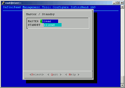
There are several additional features that you might need to perform, depending on your platform and configuration. For example, if you have an SGI ICE XA cluster with a SLES 11 SP3 platform, you need to upgrade your Mellanox OFED software for performance reasons.
The information in the following chapter explains how to configure additional features that you might want or need: