This chapter contains technical information about the Silicon Graphics Prism Deskside visualization system. The following topics are covered:
Table A-1 shows the physical and environmental specifications for the deskside system.
Table A-1. Physical Environment Specifications
Feature | Specification |
|
|---|---|---|
Deskside system dimensions | 13.5 in. (34.3 cm) tall |
|
| Note: The rear fan assembly extends an additional 1.25 inches (3 cm) from the rear of the enclosure. You must leave adequate clearance for airflow at the rear of the enclosure.
|
|
Weight | Approximately 60 lb. (27.2 kg) | May vary based on internal options |
Power requirements | 50-60 Hz and 100-120/200-240 VAC |
|
Voltage and frequency | 100-240 VAC, 50-60 Hz, (750 W max) |
|
Temperature Tolerance | +5 o C (41 oF) to +35 oC (95 oF) 5000 ft ASL or less +5 o C (41 oF) to +30 oC (86 oF) 5000 ft ASL to 10,000 ft ASL |
|
Temperature tolerance | -40 oC (-40 oF) to +85 o C (185 o F) |
|
Relative humidity | 10% to 80% operating (no condensation) 10% to 95% non-operating (no condensation) |
|
Heat dissipation | 2,560 Btu/h maximum (750 W) |
|
Maximum altitude | 10,000 ft (3,049 m) operating 40,000 ft (12,195 m) non-operating
|
|
Vibration, sine sweep (operating) | 5-500-5 Hz, 0.25 G input |
|
Vibration, sine sweep (non-operating) | 3-200-3 Hz, 0.5 G input |
|
Vibration, random | 0.582 Grms (5-300Hz) for 15 minutes each axis |
|
Vibration, random | 1.15 Grms (3-200 Hz) for 15 minutes |
|
Shock, half-sine wave (operating) | 30 G, 3 msec (vertical); |
|
Shock, trapezoidal wave (non-operating) | 35 G, 200 in./sec. |
|
Sound pressure | Approximately 65 dBA at operator position |
|
This section contains specifications and port pinout information for the I/O ports of the deskside system. The ports are discussed in the following sections:
The deskside system auto-selects the Ethernet port speed and type when the deskside system is booted, based on what it is connected to. The connector is a standard RJ-45 female. Figure A-1 shows the Ethernet port.

Table A-2 shows the cable pinout assignments for the Ethernet port.
Table A-2. Ethernet Port Pinout
Pin | Assignment |
|---|---|
1 | Transmit+ |
2 | Transmit– |
3 | Receive+ |
4 | (Reserved) |
5 | (Reserved) |
6 | Receive– |
7 | (Reserved) |
8 | (Reserved) |
The deskside system uses USB keyboard and mouse devices. Figure A-2 shows the keyboard and mouse ports.

Table A-3 shows the pinout assignments for the USB keyboard and mouse ports.
Table A-3. USB Type A Port Pinout
Pin | Assignment |
|---|---|
1 Red | VCC |
2 White | -Data |
3 Green | +Data |
4 Black | Ground |
The deskside system features one 9-pin serial console port. Figure A-3 shows the serial console port. The port is capable of transferring data at rates as high as 230 KB/s. Other features of the port include:
Programmable data, parity, and stop bits
Programmable baud rate and modem control

Table A-4 shows pinout assignments for the 9-pin male DB-9 serial console connector.
Table A-4. 9-Pin Serial Port Pinout
Pin | Assignment | Description |
|---|---|---|
1 | DCD | Data carrier detect |
2 | RXD | Receive data |
3 | TXD | Transmit data |
4 | DTR | Data terminal ready |
5 | GND | Signal ground |
6 | DSR | Data set ready |
7 | RTS | Request to send |
8 | CTS | Clear to send |
9 | RI | Ring indicator |
This section contains cable pinout information for serial cables that you can connect to your deskside system. It also describes SGI serial port converters. The following topics are covered:
Figure A-4 shows the connector pin locations for the 36-pin multi-port serial adapter connector located on the base I/O PCI card.
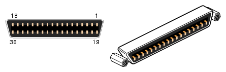
Table A-5 lists the pin assignments for the multi-port serial adapter connector.
Table A-5. Multi-port Serial Adapter Pinouts
Pin | Assignment | Pin | Assignment |
|---|---|---|---|
1 | GND | 19 | S0 DSR |
2 | S0 DCD | 20 | S0 RTS |
3 | S0 RXD | 21 | S0 CTS |
4 | S0 TXD | 22 | S0 RI |
5 | S0 DTR | 23 | GND |
6 | S1 DSR | 24 | S1 DCD |
7 | S1 RTS | 25 | S1 RXD |
8 | S1 CTS | 26 | S1 TXD |
9 | S1 RI | 27 | S1 DTR |
10 | GND | 28 | S2 DSR |
11 | S2 DCD | 29 | S2 RTS |
12 | S2 RXD | 30 | S2 CTS |
13 | S2 TXD | 31 | S2 RI |
14 | S2 DTR | 32 | GND |
15 | S3 DSR | 33 | S3 DCD |
16 | S3 RTS | 34 | S3 RXD |
17 | S3 CTS | 35 | S3 TXD |
18 | S3 RI | 36 | S3 DTR |
The deskside system's serial ports conform to the PC standard pinout for EIA standard RS-232 signals. The Linux drivers available for serial devices will vary, and no assumption is made regarding hardware or software support.
The purpose of the adapter cable is to allow the deskside system to use standard PC serial devices. Table A-6 shows the adapter cable pinout for a standard PC or Macintosh serial port.
Table A-6. Female DB-9 to Female MiniDIN8 Adapter Cable Pinout
From: Female DB | To: MiniDIN8 | PC Signal | Macintosh Signal |
|---|---|---|---|
1 | 7 | DCD | GPi |
2 | 5 | RD | RxD- |
3 | 3 | TD | TxD- |
4 | 1 | DTR | TxD+ |
5 | 4 | SG | SG |
6 | 8 | DSR | RxD+ |
7 | 6 | RTS | HSKo |
8 | 2 | CTS | HSKi |
9 | Unused | RI | Unused |
The purpose of the following adapter cable is to support ANSI/SMPTE Standard 107M-1992.
Table A-7 shows the pinout for a female DB-9 to female DB-9 adapter cable.
Table A-7. Female DB-9 to Female DB-9 Adapter Cable Pinout
Female DB-9 Connected | Female DB-9 Connected |
|---|---|
1 | Unused |
2 | To DB9 -2 (RxD-) |
3 | To DB9-8 (TxD-) |
4 | Unused |
5 | To DB9-6 and DB9-4 (GND) |
6 | To DB9-7 (RxD+) |
7 | To DB9-3 (TxD+) |
8 | Unused |
9 | Unused |
 | Note: For more detailed information, see the serial man page. |
This section provides specifications for the following ports:
Figure A-5 shows the DVI-I video port.
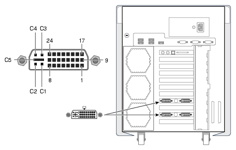
Table A-8 shows the port pinout assignments for DVI-I port(s).
Table A-8. DVI-I Video Port Pinout
Pin | Assignment | Pin | Assignment |
|---|---|---|---|
1 | DATA 2- | 16 | HOT_POWER |
2 | DATA2+ | 17 | DATA 0- |
3 | SHIELD 2/4 | 18 | DATA 0+ |
4 | DATA 4- | 19 | SHIELD 0/5 |
5 | DATA 4+ | 20 | DATA 5- |
6 | DDC_CLOCK | 21 | DATA 5+ |
7 | DDC_DATA | 22 | SHIELD CLOCK |
8 | VSYNC | 23 | CLOCK - |
9 | DATA 1- | 24 | CLOCK + |
10 | DATA 1+ | C1 | A_RED |
11 | SHIELD 1/3 | C2 | A_GREEN |
12 | DATA 3- | C3 | A_BLUE |
13 | DATA 3+ | C4 | HYNSC |
14 | +5V DC_POWER | C5 | A_GROUND2 |
15 | A_GROUND1 | C6 | A_GROUND3 |