This chapter describes various storage array configuration options to maximize data availability. It also outlines the high-level steps to configure available storage array capacity into volumes and storage partitions.
The storage arrays are designed to be reliable and feature redundant drives, controllers, power supplies, and fans. This hardware redundancy keeps the storage array working if a component fails. In addition, you can use the storage management software to implement the data protection strategies described in the following sections:
For conceptual information and detailed procedures for the strategies describes, see "Learn About Data Protection Strategies" in the Array Management window online help.
The storage management software has two premium features that provide data protection strategies. Remote Volume Mirroring is used to create an online, real-time replication of data between storage arrays over a remote distance, while Snapcopy Volume Creation provides a way to more efficiently copy data either for backup or for application testing.
The following sections provide a brief overview of the premium features used for data protection strategies.
When you create a remote volume mirror, a mirrored volume pair is created, which consists of a primary volume on a primary storage array and a second volume on a secondary storage array. When the mirror relationship is first created, data from the primary volume is copied in its entirety to the secondary volume. The secondary volume maintains a mirror (or copy) of the data from its associated primary volume. In the event of a disaster or catastrophic failure at the primary site, a manual role reversal can be performed by the system administrator to promote the secondary volume to a primary role. Hosts will then be able to access the newly promoted volume and business operations can continue.
A snapcopy volume is a point-in-time image of a volume. It is the logical equivalent of a complete physical copy, but you create it much more quickly and it requires less disk space.
Typically, a snapcopy volume is created so that an application, such as a backup application, can access the snapcopy volume and read the data while the base volume remains online and user-accessible. When the backup completes, the snapcopy volume is no longer needed. You can also create several snapcopy volumes of a base volume and write data to the snapcopy volumes to perform testing and analysis. For example, before upgrading a database management system, snapcopy volumes can be used to test different configurations. The performance data provided by the storage management software can also be used to help decide how to configure the live database system.
RAID is an acronym for Redundant Array of Independent Disks. It describes a storage solution in which the same data or information about the data (parity) is stored in different places on multiple hard disks. By placing data on multiple disks, I/O operations overlap and performance improves. If a disk drive in a volume group fails, the redundant or parity data can be used to regenerate the user data on replacement disk drives.
RAID relies on a series of configurations, called levels, to determine how user and redundancy data is written and retrieved from the drives. This storage management software offers four formal RAID level configurations: RAID levels 0, 1, 3, and 5. Table 2-1 describes these configurations. Each level provides different performance and protection features.
RAID levels 1, 3, and 5 write redundancy data to the drive media for fault tolerance. The redundancy data might be a copy of the data (mirrored) or an error-correcting code derived from the data. If a drive fails, the redundancy data can be used to quickly reconstruct information.
Table 2-1. RAID Level Configurations
Data protection strategies provided by the storage system hardware include cache memory, hot spare drives, background media scans, and channel protection.
Write caching can increase I/O performance during data transfers. Caching also increases the risk for data loss if a controller (or its memory) fails while unwritten data resides in cache memory. Use write cache mirroring to protect data during a controller or cache memory failure. When you enable write cache mirroring, cached data is mirrored across two redundant controllers with the same cache size. The data written to the cache memory of one controller is also written to the cache memory of the other controller. Therefore, if one controller fails, the other can complete all outstanding write operations. Enable the Write Cache Mirroring parameter for each volume by using the Volume > Properties option in the Array Management window.
To prevent data loss or corruption, the controller periodically writes cache data to disk (flushes the cache). When the amount of unwritten data in cache reaches a certain level, called a start percentage, or when data has been in cache for a predetermined amount of time, the software signals the controller to write the data to disk. The controller writes to disk until the amount of data in cache drops to a stop percentage level. Start and stop percentages can be configured by the user. For example, you can specify that the controller start flushing the cache when the cache reaches 80% full and stop flushing the cache when the cache reaches 16% full.
For maximum data protection, you can choose low start and stop percentages. However, in both cases this increases the chance that data needed for a host read will not be in the cache, which decreases the cache hit percentage (described in Table 2-6), and therefore the I/O request rate (also described in Table 2-6). Choosing low start and stop percentages also increases the number of disk writes necessary to maintain the cache level, increasing system overhead and further decreasing performance.
If a power outage occurs, data in the cache that has not been written to the drive media will be lost, even if it is mirrored to the cache memory of both controllers. For protection against this occurrence, batteries in the controller enclosures and array enclosures protect the cache against power outages. Change the controller enclosure and array enclosure batteries at the recommended time intervals. The TPSSM storage management software features a battery age clock you can set when you replace a battery. This clock keeps track of the age (in days) of the battery so you know when it is time to replace the battery. You will receive a critical alert notification when the battery is nearing expiration and when it has reached expiration.
For more information about controller enclosure batteries or the UPS, see the SGI InfiniteStorage TP9500 and SGI InfiniteStorage TP9700 RAID User's Guide.
A valuable strategy to keep data available is to assign available drives in the storage array as hot spare drives. A hot spare is a drive containing no data that acts as a standby in the storage array in case a drive fails in a RAID 1, 3, or 5 volume. The hot spare drive adds another level of protection to the storage array.
If a drive fails in the storage array, the hot spare is automatically substituted for the failed drive without requiring a physical swap. If the hot spare drive is available when a drive fails, the controller will use redundancy data to reconstruct the data from the failed drive to the hot spare drive. When you have physically replaced the failed drive, the data from the hot spare is copied back to the replacement drive. This is called copyback.
If you do not have a hot spare, you can still replace a failed disk drive while the storage array is operating. If the drive is part of a RAID 1, 3, or 5 volume group, the controller will use redundancy data to automatically reconstruct the data from the failed drive to the replacement drive. This is called reconstruction.
A media scan is a background process performed by the controllers to provide error detection on the drive media. A media scan detects errors and reports them to the Event Log.
The media scan must be enabled for the entire storage array as well as enabled on each volume.
The media scan runs on all volumes in the storage array for which it has been enabled. The advantage of enabling the media scan process is that the process can find media errors before they disrupt normal drive reads and writes. The media scan process scans all volume data to verify that it can be accessed and, if you enable a redundancy check, scans the volume redundancy data at the same time.
In a SCSI environment, whether or not the volume group candidate has channel protection depends on the RAID level of the volume group and how many drives are present on any single drive channel. For example, a RAID 5 volume group would not have channel protection if more than one drive was present on a single drive channel.
In a Fibre Channel environment, channel protection is usually present for any volume group candidate because when the storage array is properly cabled there are two redundant arbitrated loops for each drive.
 | Caution: Executing destructive commands on a storage array can cause serious damage, including data loss. Without password protection, all options are available within this storage management software. |
The storage management software provides a number of security features to protect data, including generation numbering to prevent replay attacks. Hashing and encryption are employed to guard against client spoofing and snooping.
For added security, you can configure a password for each storage array you manage. Because the password is stored on the storage array, each storage array that you want to be password protected will need a password. A specified password protects any options that the controller firmware deems destructive. These options include any functions that change the state of the storage array such as creation of volumes, modification of cache settings, and so on.
After the password has been set on the storage array, you will be prompted for that password the first time you attempt a destructive operation in the Array Management Window. You will be asked for the password only once during a single management session.
 | Note: If you forget the password, contact technical support. |
For storage arrays with password and alert notifications configured, any attempts to access the storage array without the correct password will be reported. If a password is entered incorrectly, an information major event log (MEL) event is logged, indicating that an invalid password or no password has been entered.
If the password is entered incorrectly 10 times within 10 minutes, both controllers will enter lockout mode. The lockout mode will last for 10 minutes, during which time both controllers will deny any attempts to enter a password to access the storage array.
| Note: if the controllers are reset, the password failure counter will be cleared and access to the storage array can be attempted again. If the password is entered incorrectly after 10 minutes, the controllers will re-enter lockout mode. |
A critical MEL event will be logged to the event log, indicating that the controllers have entered lockout mode. After the 10 minute lockout period has elapsed, the controllers will reset the password failure counter and unlock themselves.
When configuring a storage array, consider appropriate data protection strategies as well as how the total storage capacity will be organized into volumes and shared among hosts in the storage enterprise.
You can configure volumes from either unconfigured capacity or free capacity in a storage array as described in Table 2-2.
Table 2-2. Creating Volumes from Unconfigured or Free Capacity
If you create the volume from... | Then perform this activity... |
|---|---|
First define the volume group, specifying two parameters: RAID level and capacity. (Capacity refers to how large you want the volume group to be, that is, how many drives to include in the volume group.) Next, specify the volume parameters for the first volume on the volume group. Parameters include volume name, expected usage, segment size, desired capacity, controller ownership, and volume-to-LUN mapping preference. The expected usage parameter allows you to select an optimal segment size for the application that will use this storage volume. If you select either file system, database, or multimedia, and then you select Based on Expected Usage for segment size, you can optimize the segment size without knowing which specific segment size value to set. For a description of the Volume-to-LUN Mapping Preference parameter see “Related Publications”
| |
Because free capacity resides only on an existing volume group, the overall capacity (that is, the number of drives) and RAID level were already specified. Therefore, you only need to specify the volume parameters (volume name, usage, desired capacity, controller ownership, and volume-to-LUN mapping preference). Note: You can add free capacity to a volume group by using the Volume Group > Add Free Capacity option. |
After creating all volumes and assigning volume-to-LUN mappings, the host-based scsiha and ioconfig utilities are used to register the volume with the operating system. The host-based tpssmdevices utility is used to associate the mapping between the physical device name and the volume name. See “Storage Partitioning” for more information.
| Caution: Increasing the capacity of a standard volume is only supported on certain operating systems. If volume capacity is increased on a host operating system that is unsupported, the expanded capacity will be unusable, and you cannot restore the original volume capacity. |
Volume capacity of standard volumes and snapcopy repository volumes is increased by using Dynamic Volume Expansion (DVE). This feature expands the capacity of an existing volume by either using a volume's free capacity on an existing volume group, or by adding unconfigured capacity (new or unassigned drives) to the volume group. You can expand a volume dynamically without losing access to it or to any other volumes.
Increasing the capacity of a snapshot repository volume does not increase the capacity of the associated snapcopy volume. However, unless the capacity of the base volume is also increased, it is not necessary to increase the size of the snapcopy volume. The snapcopy volume's capacity is always based on the capacity of the base volume at the time the snapcopy volume is created.
You cannot add storage capacity to a volume if:
One or more hot spare drives are in use in the volume.
The volume has a non-optimal status.
Any volume in the volume group is in any state of modification.
The controller that owns this volume is in the process of adding capacity to another volume. (Each controller can add capacity to only one volume at a time.)
No free capacity exists in the volume group, and no unconfigured capacity is available to add to the volume group.
No unconfigured capacity (in the form of drives) is available to add to the volume group.
The Mappings View tab is used to define the storage topology elements (host groups, hosts, host ports, and so on), to define volume-to-LUN mappings, and to view Storage Partitioning and heterogeneous host information. The Mappings View tab has two views, Topology view and Defined Mappings view, shown in Figure 2-1 and described in Table 2-3.
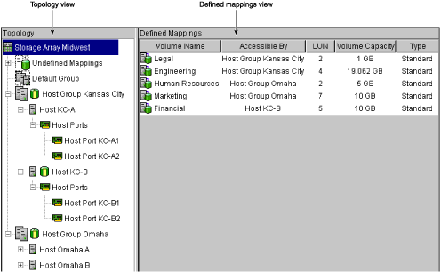
Table 2-4 describes the topological elements displayed in the Mappings View window in Figure 2-1.
Table 2-4. Volume-to-LUN Terminology
Term | Description |
|---|---|
Storage Partitioning Topology | A collection of nodes (default group, host groups, hosts, and host ports) shown in the Topology view of the Mappings View tab. You must define the various topological elements if you want to define specific volume-to-LUN mappings and storage partitions for host groups or hosts. |
A node in the Topology view that designates all host groups, hosts, and host ports that: (1) have no specific volume-to-LUN mappings and (2) share access to any volumes that were automatically assigned default LUN mappings by the controller firmware during volume creation. | |
An optional topological element that you define if you want to designate a collection of hosts that will share access to the same volumes. The host group is a logical entity. | |
A computer that is attached to the storage array and accesses various volumes on the storage array through its host ports (host bus adapters). You can define specific volume-to-LUN mappings to an individual host or assign the host to a host group that shares access to one or more volumes using the Define Host Wizard.. | |
The physical connection that allows a host to gain access to the volumes in the storage array. When the host bus adapter only has one physical connection (host port), the terms host port and host bus adapter are synonymous. Host ports can be automatically detected by the storage management software after the storage array has been connected and powered-up. Therefore, if you want to define specific volume-to-LUN mappings for a particular host or create storage partitions, you must define the host's associated host ports. Initially, all detected host ports belong to the Default Group. Therefore, if during volume creation, you had a LUN automatically assigned to a volume, that volume will be accessible by any of the host ports in the Default Group. If you have the Storage Partitioning feature enabled, then you should always choose to map the volume later using the options in the Mappings View so that a LUN is not automatically assigned to a volume during volume creation. Use the host bus adapter utility to find the World Wide Name (WWN) of the host port. (This is the host port identifier shown in the Define New Host Port dialog in the Mappings View.) The WWNs for the host ports on a particular host are used to define the host ports and associate them with a particular host using the Define New Host Port dialog. If necessary, see your operating system or host bus adapter documentation for more information. If a host port is moved, any volume-to-LUN mappings must be re-mapped. Access to your data will be lost until this is done. | |
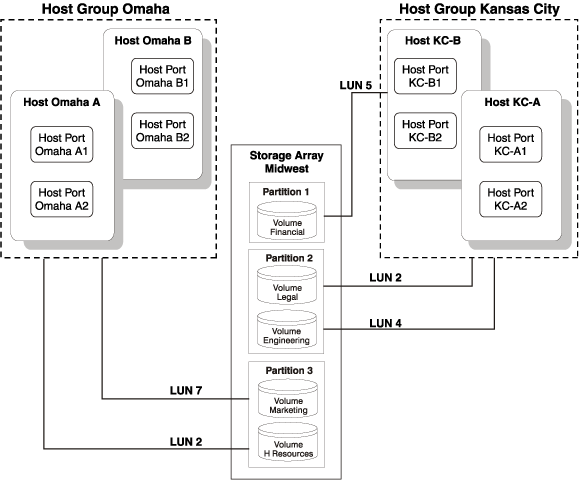
The number a host uses to access a volume on a storage array. Each host has its own LUN address space. Therefore, the same LUN may be used by different hosts to access different volumes on the storage array. However, a volume can only be mapped to a single LUN. A volume cannot be mapped to more than one host group or host. For example, Figure 2-5 shows that Host Group KC may access Volume Legal using LUN 2 and Host Group Omaha may access Volume H Resources also using LUN 2. | |
Default | During volume creation, you can specify that you want to have the software assign a LUN automatically to the volume or that you want to map a LUN to the volume later. If you have the Storage Partitioning feature enabled, then you should always choose to map the volume later using the options in the Mappings View so that a LUN is not automatically assigned to a volume during volume creation. Any volumes that are given automatic (default) volume-to-LUN mappings can be accessed by all host groups or hosts that do not have specific volume-to-LUN mappings. These host groups and hosts are shown as part of the Default Group in the Topology view of the Mappings View. |
Specific Volume-to-LUN mapping | A specific volume-to-LUN mapping occurs when you select a defined host group or host in the Topology view and select the Storage Partitioning Wizard or Define Additional Mapping option to assign a volume a specific LUN (volume-to-LUN mapping). This designates that only the selected host group or host has access to that particular volume through the assigned LUN. You can define one or more specific volume-to-LUN mappings for a host group or host. The Storage Partitioning feature must be enabled to create specific mappings. |
Storage Partitioning is a premium feature of the storage management software and must be enabled either by you or your storage vendor.
A storage partition is a logical entity consisting of one or more storage array volumes that can be shared among hosts, which may be part of a host group or accessed by a single host. A storage partition is created when you define a single host or a collection of hosts, called a host group, and then define a volume-to-LUN mapping. This mapping defines what host or host group will have access to a particular volume in your storage array. Hosts and host groups can only access data through assigned volume-to-LUN mappings. Each volume can be mapped to one storage partition.
Storage partitions can quickly be created with the Storage Partitioning Wizard. The Wizard contains the major steps required to specify which hosts, volumes, and associated logical unit numbers (LUNs) will be included in the partition.
A maximum of 256 volumes per partition for controllers with firmware 5.40 and later or 32 volumes per partition for controllers with firmware earlier than 5.40 can be defined; this is limited to the total number of volumes on your storage array. A maximum of 64 storage partitions can be supported by the storage management software. The software can further support up to two host ports in each host and up to eight ports in each host group, allowing a four-way cluster of dual-adapter hosts. After the total storage capacity is configured into volumes, those volumes need to be shared among hosts in the storage array. Storage Partitioning allows hosts with the same or different operating systems (heterogeneous hosts) to share access to a storage array.
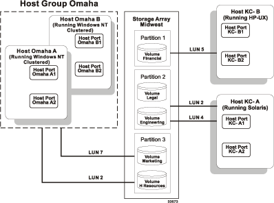
In the example shown in Figure 2-2, four hosts (Omaha A and B and KC-A and B) are connected to Storage Array Midwest. Host KC-B has exclusive access to Volume Financial. Hosts KC-A and KC-B (Host Group Kansas City) share access to Volumes Legal and Engineering, and Omaha A and Omaha B (Host Group Omaha) share access to Volumes Marketing and H Resources. So, three storage partitions were configured.
The first partition is composed of Volume Financial. This volume is accessed by Host KC-B using LUN 5. Even though Host KC-B is part of the logical Host Group Kansas City, Host KC-A cannot access this volume because the volume-to-LUN mapping was created with Host KC-B rather than the Host Group Kansas City.
The second partition consists of Volumes Legal and Engineering. This volume-to-LUN mapping was created using Host Group Kansas City. These volumes are accessed by Hosts KC-A and KC-B in Host Group Kansas City using both LUNs 2 and 4.
The third partition consists of Volumes Marketing and H Resources. This volume-to-LUN mapping was created using Host Group Omaha. These volumes are accessed by Hosts Omaha A and Omaha B in Host Group Omaha using both LUNs 7 and 2.
| Note: A host gains access to the volumes on the storage array through the physical host ports residing on the installed host bus adapters. To ensure redundant paths to each volume, it is recommended that each host have at least two host ports. |
The next section explains how this example was configured.
Creating storage partitions involves the following three major steps:
Create volumes on the storage array.
Define storage partitions topology (host groups, hosts, and host ports).
Define volume-to-LUN mappings.
Note: The three major steps provide a basis for understanding what storage partitions are and how to create them. For specific, detailed procedures, see the Array Management window Help system.
Create Volumes on the Storage Array
As part of the volume creation, specify one of two volume-to-LUN mapping settings:
Automatic – If you are not using Storage Partitioning, specify this setting. The Automatic setting specifies that a LUN be automatically assigned to the volume using the next available LUN within the Default Group. This setting will grant volume access to host groups or hosts that have no specific volume-to-LUN mappings (designated by the Default Group in the Topology view).
Map later with Storage Partitioning – If you are using Storage Partitioning, specify this setting. The Map later setting specifies that a LUN not be assigned to the volume during volume creation. This setting allows definition of a specific volume-to-LUN mapping and creation of storage partitions.
Define Storage Partitions Topology
Storage partition topology is reconfigurable. You can do the following:
Move a host port
Replace a host port
Move a host from one host group into another host group
Delete a host group, host, or host port
Rename a host group, host, or host port
Change a volume-to-LUN mapping
Define additional volume-to-LUN mappings
The last step is to grant access to one or more volumes to a defined host group or host. You do this by defining specific volume-to-LUN mappings using the Storage Partitioning Wizard. Each host group or host is granted a unique view of partitioned storage.
Each host group or host that you define is granted a unique view of partitioned storage. A defined host group or host can access either:
Volumes with default volume-to-LUN mappings – The host group or host is part of the Default Group.
Volumes to which they have been granted access through a specific volume-to-LUN mapping – The host group or host will be part of a storage partition.
In the example in Figure 2-3, none of the topological elements have had specific volume-to-LUN mappings defined. Therefore, they appear under (as part of) the default host group and can access any volumes that have been assigned default LUNs (default volume-to-LUN mappings).
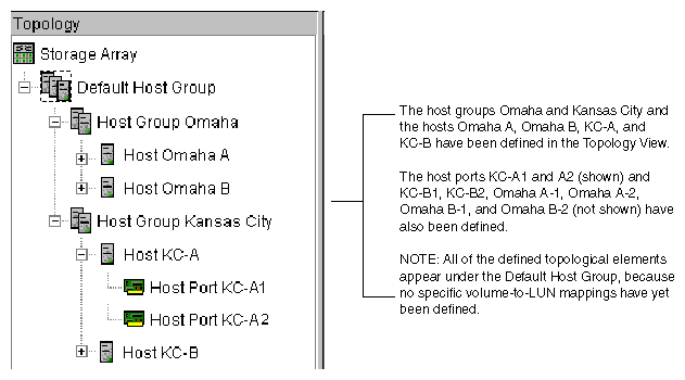
If you define specific volume-to-LUN mappings for any of the host groups or hosts, they no longer appear under the default host group; they move to under the root node, marked storage array. Also, they can no longer access volumes with default volume-to-LUN mappings. Either a host group or host can access volumes with default mappings or specific mappings, but not both.
The heterogeneous hosts portion of the Storage Partitioning feature allows hosts running different operating systems to access a single storage array. To specify different operating systems for attached hosts, you must specify the appropriate host type when you define the host ports for each host.
Host types can be completely different operating systems, such as Solaris and Windows NT, or variants of the same operating system, such as Windows NT clustered and Windows NT non-clustered. When a host type is specified, it allows the controllers in the storage array to tailor their behavior (such as LUN reporting and error conditions) depending on the operating system or variant of the host sending the information.
| Note: Heterogeneous host settings are only available with Storage Partitioning enabled. In Figure 2-5, the Storage Partitioning feature is enabled. |
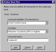
In a heterogeneous environment, you must set each host type to the appropriate operating system during host port definition (Figure 2-4). By doing this, the firmware on each controller can respond correctly for that host's operating system.
In the example shown in Figure 2-5, heterogeneous hosts have been defined on Storage Array Midwest. Four hosts (Omaha A and B and KC-A and B) are connected to Storage Array Midwest. Hosts Omaha A and Omaha B share access to Volumes Marketing and HResources. Host KC-A has exclusive access to Volumes Legal and Engineering, and Host KC-B has exclusive access to Volume Financial. So, three storage partitions have been configured. Because there are four hosts running three different operating systems, the appropriate host types must be defined for each host port to support these heterogeneous hosts.
After you define the host type for each host port, you can display the host port's host type in the Topology view by placing your cursor over the specific host port; a tooltip will display the associated host type.
This section describes the maintenance of storage arrays in the management domain, which includes the following activities.
Use the Enterprise Management window to:
Monitor the health of the storage arrays, as explained in the next section.
Configure alert notifications using the event monitor (see “Event Monitor” or the Enterprise Management window Help).
Note: To receive critical alerts, the Enterprise Management window must be running (it can be minimized).
Use the Array Management window to:
Monitor the individual logical and physical components in an individual storage array (as explained in the Array Management window Help).
Recover from storage array problems (as explained in “Recovering from Storage Array Problems”).
Monitor storage array performance and tune performance, if necessary, (as explained in “Tuning Storage Arrays ”).
| Note: The Enterprise Management window or the event monitor must be running to receive notification of critical events for the storage arrays. In addition, alert notifications must be configured in the Enterprise Management window. |
The Enterprise Management window provides a summary of the conditions of all known storage arrays in the management domain. Appropriate status indicators will be shown in the Device Tree, the Device Table, and in the health summary status area in the lower-left corner of the Enterprise Management window, as shown in Figure 2-6.
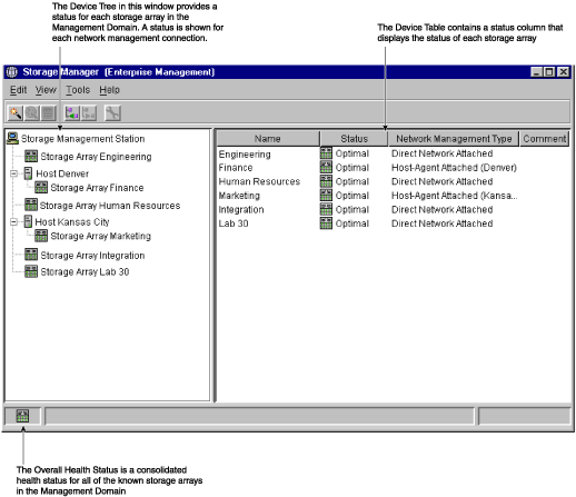
Table 2-5 provides information about the storage array status icons that display as follows:
In the Device Tree, Device Table, and Overall Health Status areas of the Enterprise Management window.
As the root node of the Logical view tree in the Array Management window.
Table 2-5. Storage Array Status Indications
Status
Icon
Indication

Every component in the storage array is in the desired working condition.

A problem with a storage array requires intervention to correct. To correct the problem, you should start the Array Management window for the particular storage array and then use Recovery Guru to pinpoint the cause of the problem and obtain appropriate instructions.

A Needs Attention condition has been corrected and the storage array is currently transitioning to an Optimal state (for example, a reconstruction operation is in progress). A Fixing status requires no action unless you want to check on the progress of the operation in the Array Management window.
Note: Some recovery actions cause the storage array state to change directly from Needs Attention to Optimal, without an interim state of Fixing. The Fixing status icon is not displayed in the Overall Health Status area (Optimal is displayed instead).

The storage management station cannot communicate with the only controller or both controllers over its network management connection to the storage array.
Note: The Unresponsive icon is not displayed in the Logical view of the Array Management window. If the Array Management window is open and the storage array becomes Unresponsive, the last known state (Optimal, Needs Attention, or Fixing) is shown.

You have started the Enterprise Management window and the storage management software is establishing contact with the storage array.
Note: This status is not displayed in the Logical view of the Array Management window.
The event monitor runs continuously in the background monitoring activity on a storage array and checking for critical problems (for example, impending drive failures or failed controllers). If the event monitor detects any critical problems, it can notify a remote system using e-mail and/or simple network management protocol (SNMP) trap messages whenever the Enterprise Management window is not running.
The event monitor is a separate program bundled with the client software and must be installed with the storage management software. The client/event monitor is installed on a storage management station or host connected to the storage arrays. For continuous monitoring, install the event monitor on a computer that runs 24 hours a day. Even if you choose not to install the event monitor, alert notifications must still be configured on the computer where the client software is installed, because alerts will be sent as long as the Enterprise Management window is running.
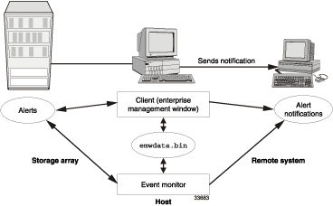
Figure 2-7 shows how the event monitor and the Enterprise Management window client software send alerts to a remote system. The storage management station contains a file with the name of the storage array being monitored and the address where alerts will be sent. The alerts and errors that occur on the storage array are continuously being monitored by the client software and the event monitor. The event monitor takes over for the client after the client software package is shut down. When an event is detected, a notification is sent to the remote system.
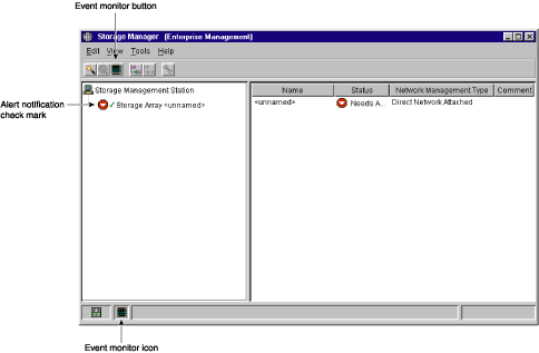
Because the event monitor and the Enterprise Management window share the information to send alert messages, the Enterprise Management window contains some visual cues to assist in the event monitor installation and synchronization. The parts of the Enterprise Management window that are related to event monitoring are shown in Figure 2-7.
Using the event monitor involves three key steps:
Install the client software.
The event monitor is packaged with the client software and installs automatically with the client software. It is recommended that you run the event monitor on one machine that will run continuously. To prevent receipt of duplicate alert notifications of the same critical event on a storage array, disable the event monitor on all but one storage management station.
You must have administrative permissions to install software on the computer where the event monitor will reside. After the storage management software has been installed, the icon shown in Figure 2-8 will be present in the lower-left corner of the Enterprise Management window.
Set up the alert destinations for the storage arrays you want to monitor from the Enterprise Management window.
A check mark indicates where the alert is set (storage management station, host, or storage array). When a critical problem occurs on the storage array, the event monitor will send a notification to the appropriate alert destinations that were specified.
Synchronize the Enterprise Management window and the event monitor. After it has been installed, the event monitor continues to monitor storage arrays and send alerts as long as it continues to run. If you make a configuration change in the Enterprise Management window, such as adding or removing a storage array or setting additional alert destinations, you should manually synchronize the Enterprise Management window and the event monitor.
Alert notification settings must be configured to receive e-mail or SNMP notifications if a critical event occurs on a storage array. The notification displays a summary of the critical event and details about the affected storage array, including:
Name of the affected storage array
Host IP address (only for a storage array managed through a host-agent)
Host name/ID (shown as directly managed if the storage array is managed through each controller's Ethernet connection)
Event error type related to an Event Log entry
Date and time when the event occurred
Brief description of the event
Note: To set up alert notifications using SNMP traps, you must copy and compile a management information base (MIB) file on the designated network management station. See the SGI TP9500 RAID Installation and Upgrade Guide or the SGI InfiniteStorage TP9700 RAID Installation and Upgrade Guide for more information.
Configuring Alert Notifications
Select a node in the Enterprise Management window that will display alert notifications for the storage arrays you want to monitor. You can set the alert notifications at any level:
Every storage array in the management domain
Every storage array attached and managed through a particular host
An individual storage array
Configure e-mail destinations, if desired. You must provide a mail server name and an e-mail sender address for the e-mail addresses to work.
Configure SNMP trap destinations, if desired. The SNMP trap destination is the IP address or the host name of a station running an SNMP service, such as a Network Management Station.
Use the Edit > Alert option in the Enterprise Management window to configure the system to send e-mail notifications to a specified customer support group if a critical event occurs on one of the storage arrays. After it is properly set up, the e-mail alert notification includes a summary of the critical event, detailed information about the affected storage array, and custom contact information.
| Note: If you do not configure this feature, the e-mail alert notification will contain only a summary of the critical event. |
Configuring the Customer Support Alert Notification
Create a text file containing the contact information you want to send to the customer support group. For example, include the names and pager numbers of the network administrators.
Name the file userdata.txt and save it in the home directory (for example, Winnt\profiles\ or usr\ ) on the client machine that is used to manage the storage array.
Note: This may be your host machine if you installed the client software on the host. Configure the alert notifications by selecting the appropriate node in the Device Tree and then selecting Edit > Alert > Destinations. Specify the e-mail address of the customer support organization. For more information on selecting nodes for alert notifications, see “Configuring E-Mail and SNMP Alert Notification Settings” in the Enterprise Management window Help system.
Note: Remember to set up the mail server and sender address by selecting Edit > Alert > Global Settings.
| Note: The Enterprise Management window or the event monitor must be running (it can be minimized) for critical alert notifications to be sent. In addition, you must have configured the alert notifications in the Enterprise Management window. |
Use the Recovery Guru to help troubleshoot storage array problems. Where necessary, use the hardware documentation in conjunction with the recovery steps to replace failed components.
When you monitor a storage array, there are several indicat ors of a storage array failure:
A Needs Attention storage array icon is displayed in the following:
Overall Health Status area, Device Tree View, and Device Table of the Enterprise Management window.
Logical view of the Array Management window.
The Recovery Guru toolbar button in the Array Management window changes from an Optimal to a Needs Attention status and flashes.
Non-optimal component icons are displayed in the Array Management window Logical/Physical View.
You receive critical SNMP or e-mail notifications.
Hardware fault lights are displayed.
In Figure 2-9, the Array Management window for storage array Engineering shows indications of a components problem and a Needs Attention status in the Logical/Physical View.
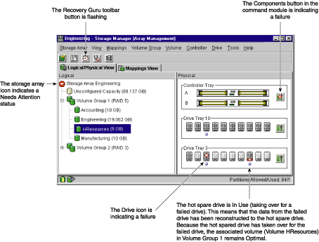
You may also receive failure notifications about this storage array at a network storage management station or in e-mail. In addition, hardware fault lights display on the affected controller and drive enclosures.
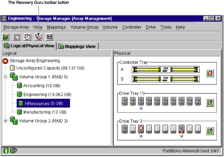
The Recovery Guru is a component of the Array Management window in the TPSSM client package. The Recovery Guru diagnoses storage array problems and recommends recovery procedures to fix the problems. To display the Recovery Guru, select the Recovery Guru toolbar button in the Array Management window, called out in Figure 2-10, or select the Storage Array > Recovery Guru menu option.
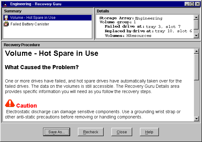
The Recovery Guru window, as shown in Figure 2-11, is divided into three areas: Summary, Details, and Recovery Procedure. The Summary area lists storage array problems. The Details area displays informatin about the selected problem in the Summary area. The Recovery Procedure area lists the appropriate steps to follow for the selected problem in the Summary area.
For example, in Figure 2-11, the Summary area shows that there are two different failures in this storage array: a hot spare in use and a failed battery canister. The Details area shows that in Volume HResources, a hot spare drive in tray 10, slot 6 has replaced a failed drive in tray 3, slot 7. The Recovery Procedure area explains the cause of the problem selected in the Summary area, and describes the appropriate procedures needed to recover from this failure.
As you follow the recovery procedure to replace the failed drive, the storage array status changes to Fixing, the associated volume (HResources) status changes to Degraded-Modification in Progress, and the replaced drive status changes to Replaced. The data that was reconstructed to the hot spare drive is now being copied back to the replaced drive. These changes are shown in Figure 2-12.
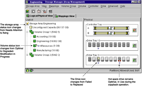
When the copyback operation is finished, the status icons change to reflect the optimal status of the components, as shown in Figure 2-13.
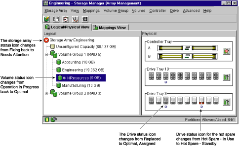
After you fix the failed drive in the drive enclosure, the following changes occur:
The Storage Array icon in the Logical view returns to Optimal.
The Storage Array icon in the Enterprise Management window changes from a Needs Attention status to an Optimal status.
The Recovery Guru button stops blinking.
Note: For the Recovery Guru buttom to register Optimal status, the failed battery must also be replaced.
In general, when you are configuring a storage array, the default values should provide optimal performance. However, if you want to tune the storage array after initial configuration, several options are available in the Array Management window for optimizing storage array and application performance. These tuning options are described in Table 2-6.
| Note: You can perform any of the tuning operations while the storage array is processing I/O. |
Table 2-6. Tuning Options in Array Management Window
Option | Description |
|---|---|
Storage Array > Monitor Performance | Use this option to monitor storage array performance in real-time and save performance data to a file for later analysis. You can specify the volumes and/or controllers to monitor and the polling interval. Data provided from a session includes I/O load, cache hit percentage, how your I/O is allocated between reads and writes, transfer rates and I/O request rates for the volumes being monitored or for the entire storage array. - The cache hit percentage is the percentage of reads that are serviced with data from the cache rather than requiring a read from disk. - A transfer rate is the amount of data in kilobytes per second that moves through the I/O data path (also called throughput). - An I/O request rate is the average number of I/O requests serviced per second. For more information, see the Array Management window Help. |
Storage Array > Change Cache Settings | Use this option to specify the start flush and stop flush parameters (expressed in percentage of cache memory that contains unwritten data) and the cache block size for the storage array. Low start and stop flush percentages increase data safety but decrease the cache hit percentage and therefore the I/O request rate. For more information, see “Protect Data in the Controller Cache Memory” and the Array Management window Help. |
Volume Group > Change RAID Level | Use this option to change the RAID level of a volume group when either of the following occurs: 1. The application read or write percentages on a volume indicate that its current RAID level may not be appropriate for desired performance. 2. You want to change the volume group's redundancy (such as changing from RAID 0 to RAID 5). Applications with a high read percentage perform very well using RAID 5 volumes because of the outstanding read performance of the RAID 5 configuration. However, applications with a low read percentage (write-intensive) do not perform as well on RAID 5 volumes because of the way a controller writes data and redundancy data to the drives in a RAID 5 volume group. If there is a low percentage of read activity relative to write activity, you might consider changing the RAID level of a volume group from RAID 5 to RAID 1 for faster performance. |
Volume Group > Change Ownership | If a particular controller has considerably more I/O activity than expected, consider moving a volume group to the other controller in the storage array by using this option. |
Volume > Change Segment Size | A segment is the amount of data in kilobytes that the controller writes on a single drive in a volume before writing data on the next drive. When you create a volume, the default segment size is normally a good choice for the expected volume usage you specify. If volume usage is different than expected, use the Volume > Change Segment Size option to change the segment size of a volume. In a read-intensive application environment with random I/O access patterns, make sure the segment size is large enough to minimize the number of drives needed to satisfy an I/O request. This leaves other drives available to satisfy other requests. A volume group data stripe is the segment size multiplied by the number of drives in the volume group used for I/O. In a single-user environment with sequential I/O access patterns, performance is optimized when a single I/O request can be serviced with a single volume group data stripe. In this case, multiple disks are used for the same request, but each disk is only accessed once. |
Volume > Properties | Use this option to set following three tuning parameters: - Write caching - Volume Modific ation Priority Write caching. To maximize I/O request rates, enable write-caching on a volume. Write caching frees an application to continue after writing to the controller cache memory, a faster operation than a disk write. The cache memory is flushed to disk when it contains a percentage of unwritten data you specify using the Storage Array > Cache Settings option. Cache read-ahead. If an individual volume is experiencing a low cache hit percentage, consider enabling cache read-ahead (or prefetch) for that volume. Cache read-ahead can increase the cache hit percentage for a sequential I/O workload. If cache read-ahead is enabled, the cache reads the data from the disk. But in addition to the requested data, the cache also fetches more data, usually from adjacent data blocks on the drive. This feature increases the chance that a future request for data could be fulfilled from the cache rather than requiring a disk access. The cache read-ahead multiplier values specify the multiplier to use for determining how many additional data blocks are read into cache. Choosing a higher cache read-ahead multiplier can increase the cache hit percentage for volumes with sequential I/O access patterns. (In the case of a random I/O pattern, the optimal multiplier is zero.) Volume modification priority. This defines how much processing time is allocated for volume modification operations versus system performance. The higher the priority, the faster that volume modification operations are completed but the slower I/O is serviced. Volume modification operations include reconstruction, copyback, initialization, defragmentation, change of RAID level, and change of segment size. |
Volume > Properties | You set the modification priority for each volume by using a slider bar on the Volume > Properties dialog. There are five relative settings on the reconstruction rate slider bar, ranging from Lowest to Highest. The actual speed of each setting is determined by the controller. Choose the Lowest setting to maximize the I/O request rate. If the controller is idle (not servicing any I/O), it will ignore the individual volume rate settings and process volume modification operations as quickly as possible. |
There are two separate Help systems, one in the Enterprise Management window and one in the Array Management window. These are distinct Help systems that can only be accessed when you are in the appropriate window. Table 2-7 is a task-based index to the appropriate Help system.
Table 2-7. Task Reference: Populating a Management Domain
Table 2-8 describes the Storage Array Configuration Help system.
Table 2-8. Task Reference: Storage Array Configuration
Table 2-9 describes the Performance and Tuning Help system.
Table 2-9. Task Reference: Performance and Tuning
To perform this task... | Use this option | See the Help system in... |
|---|---|---|
Changing cache settings on a storage array | Storage Array > Change Cache Settings | Array Management window |
Volume > Properties | Array Management window | |
Changing media scan settings on a storage array | Storage Array > Change Media Scan Settings | Array Management window |
Volume > Properties | Array Management window | |
Volume Group > Change Ownership | Array Management window | |
Volume > Properties | Array Management window | |
Volume Group > Change RAID Level | Array Management window | |
Volume > Change Segment Size | Array Management window | |
Storage Array > Monitor Performance | Array Management window |
Table 2-10 describes the Event Notification Help system.
Table 2-10. Task Reference: Event Notification
Table 2-11 describes the Recovering From Problems Help system.
Table 2-11. Task Reference: Recovering From Problems
Table 2-12 describes the Miscellaneous System Administration Help system.
Table 2-12. Task Reference: Miscellaneous System Administration