This chapter provides safety instructions to follow when using and maintaining your workstation. It also describes how to install and remove the workstation's customer-replaceable units (CRUs). This information is covered in the following sections:
Before you perform any type of maintenance to your system, read the following safety instructions:
Follow all warnings and instructions marked on the product and noted in this and other documentation included with the product.
Unplug this product from the wall outlet before you clean it. Do not use liquid cleaners or aerosol cleaners. Use a damp cloth for cleaning.
Do not use this product near water.
Do not place this product or components of this product on an unstable cart, stand, or table. The product may fall, causing serious damage to the product.
Slots and openings on the cabinet and components are provided for ventilation, reliable operation, and protection from overheating of the product. These slots and openings must not be blocked or covered. This product should never be placed near or over a radiator or heat register, or in a built-in installation unless proper ventilation is provided.
This product should be operated from the type of power indicated on the marking label. If you are not sure of the type of power available, consult your dealer or local power company.
Do not allow anything to rest on the power cord. Do not locate this product where persons will walk on the cord.
Do not use extension cords with your SGI system.
Never push objects of any kind into this product through cabinet slots because they may touch dangerous voltage points or short out parts that could result in a fire or electric shock.
Never spill liquid of any kind on the product.
Do not attempt to service this product yourself except as noted in this guide. Opening or removing covers of internal components may expose you to dangerous voltage points or other risks. Refer all servicing to qualified service personnel.
Unplug this product from the wall outlet and refer servicing to qualified service personnel under the following conditions:
If the power cord or plug is damaged or frayed.
If the product has been exposed to rain, water, or other type of liquid.
If the product does not operate normally when the operating instructions are followed.

Note: Adjust only those controls that are covered by the operating instructions, because improper adjustment of other controls may result in damage and will often require extensive work by a qualified technician to restore the product to normal condition. If the product has been dropped or the cabinet has been damaged.
If the product exhibits a distinct change in performance, which indicates a need for service.
Only qualified service personnel should replace a soldered lithium battery in the workstation, and only with the same type or an equivalent type recommended by the manufacturer. Please see the “Lithium Battery Statement ” in Appendix C for more information. The battery can explode if it is replaced incorrectly.
Use only the proper type of power supply cord set (provided with the system) for this unit.

Caution: Electronic equipment can be irreparably damaged by electrostatic discharge (ESD). Always follow these preventive measures when you handle a system component:
- Remove a component from its antistatic bag only when you are ready to install it.
- If you handle a component before installation, do not place it on surfaces that produce ESD (carpeting, for example) or near devices that create static electricity.
- Attach a static wrist strap to a grounded connection on your system when you install or remove a component.
To access and remove/replace internal system components, follow these steps to remove and replace the enclosure cover:
Unfasten the two screws that hold the enclosure in the rack.
Use two people to slide it out and set it on a table or other stable work surface.
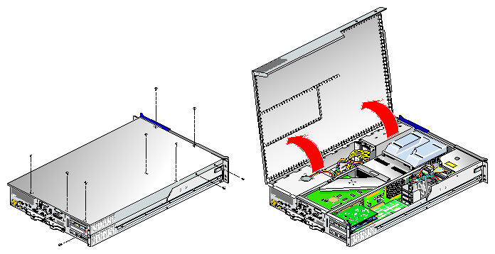
Remove the ten Phillips screws as shown in Figure 3-1 and lift the hinged cover.
Follow the instructions in this chapter for adding/removing the internal components such as PCI cards or memory DIMMs.
After completing the procedure(s) needed, close and secure the enclosure by replacing the cover and tightening the ten screws as shown in Figure 3-2.
Using two people, insert the enclosure back into the rack and secure it with the two screws you removed in step 1.

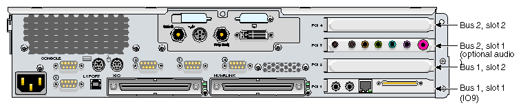
The rack-mountable workstation supports PCI and PCI–X cards. The following procedure describes how to install and remove a PCI or PCI–X card from a workstation. This procedure applies to both the first enclosure and the optional second enclosure. Figure 3-3 shows the location of the PCI and PCI–X card slots in both the first and second enclosures.
For an updated list of supported PCI and PCI–X cards, see SGI Supportfolio at http://support.sgi.com.
This section explains how to perform the following procedures:
To install a PCI or PCI–X card, follow these steps:
Power off the system. For instructions on how to power off the system, see “Using the Workstation” in Chapter 1.
Disconnect all of the cables at the rear of the system.

Warning: Components may be hot. To avoid injury, allow the components to cool for approximately five minutes before you proceed with these instructions. If your system is rackmounted, remove the two screws that secure the enclosure to the front rails of the rack. If your system is not rackmounted, proceed to the next step.
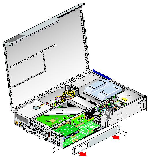
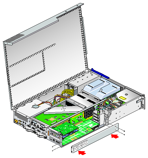
If you are installing a card in one of the two lowermost card slots, you must also remove the lower PCI/PCI–X support bracket that covers the two lowermost slots as shown in Figure 3-4 by removing the four Phillips screws.
If a blanking plate covers the slot that is needed for the installation, remove the retaining screw as shown in Figure 3-5 and the blanking plate.
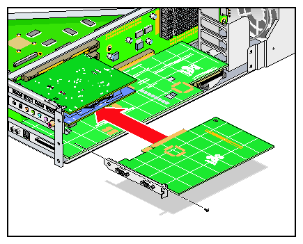
If you want to install a PCI/PCI–X card, insert the card into the slot by pushing the card into the connector until it is properly seated and install the retaining screw as shown in Figure 3-6. If you have installed a card (not an IO9 card) into one of the two lowermost slots, proceed to step 12. If you have installed the card into one of the upper two slots, proceed to step 14.
If you have installed a card in one of the two bottom–most card slots, replace the lower PCI/PCI–X support bracket that covers the two bottom–most slots and screw in the four Phillips screws as shown in Figure 3-7.
Caution: To prevent pinching and damaging of the IDE and SCSI cables, make sure that both of these cables are tucked underneath the IO9 card and safely away from the lower PCI/PCI–X support bracket that you are replacing. Close the hinged cover on the system and screw in the ten Phillips screws you removed to secure the cover as shown in Figure 3-2.
If your system is rackmounted, proceed to the next step. If your system is free-standing, proceed to step 13.
Using two people, slide the enclosure back into the rack.
Install the two screws that secure the enclosure to the front rails of the rack.
Install the two screws that secure the enclosure to the rear of the rack.
Install all of the cables at the rear of the system.
Power on the system. For instructions on how to power on the system, see “Using the Workstation” in Chapter 1.

To remove a PCI or PCI–X card, follow these steps:
Power off the system. For instructions on how to power off the system, see “Using the Workstation” in Chapter 1.
Disconnect all of the cables at the rear of the system.
Warning: Components may be hot. To avoid injury, allow the components to cool for approximately five minutes before you proceed with these instructions. Remove the two screws that secure the enclosure to the front rails of the rack.
Remove the two screws that secure the enclosure to the rear of the rack.
Using two people, pull the enclosure from the rack and move it to a table or other stable work area.
To access the PCI cards, first remove the ten Phillips screws as shown in Figure 7-1 on page 131, and then lift the hinged cover.
If you are removing a card from one of the two lowermost slots, you must also remove the lower PCI/PCI–X support bracket that covers the two lowermost slots by unscrewing the four Phillips screws shown in Figure 3-8.
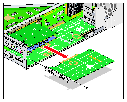
If you are removing a card from one of the upper three slots, unscrew the retaining screw and extract the card as shown in Figure 3-9. Place the card on an ESD-safe surface. (If you are removing a card from one of the upper two slots, after you have removed the card, proceed to step 12. Otherwise, proceed to the next step.)
If you are replacing the card you have removed, proceed to “Installing a Card”. Start with step 10 in that procedure to begin the card replacement. If you are not replacing the card you have removed, proceed to the next step.
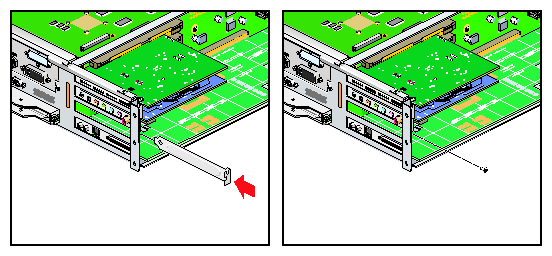
If you have removed a card from one of the upper three slots, place a blanking plate to cover the slot and screw in the retaining screw as shown in Figure 3-10. After installing the blanking plate, if you have removed a card from one of the two lowermost slots, proceed to the next step. Otherwise, proceed to step 15.
If you have removed a card from one of the two bottom–most card slots, replace the lower PCI–PCI–X support bracket that covers the two bottom–most slots, and screw in the four Phillips screws as shown in Figure 3-11.
Close the hinged cover on the system and screw in the ten Phillips screws, which you had removed as shown in Figure 3-2, to secure the cover.
If your system is rackmounted, proceed to the next step. If your system is free-standing, proceed to step 17.
Using two people, slide the enclosure back into the rack.
Install the two screws that secure the enclosure to the front rails of the rack.
Install the two screws that secure the enclosure to the rear of the rack.
Install all of the cables at the rear of the system.
Power on the system. If you need instructions on how to power on the system, see “Using the Workstation” in Chapter 1.
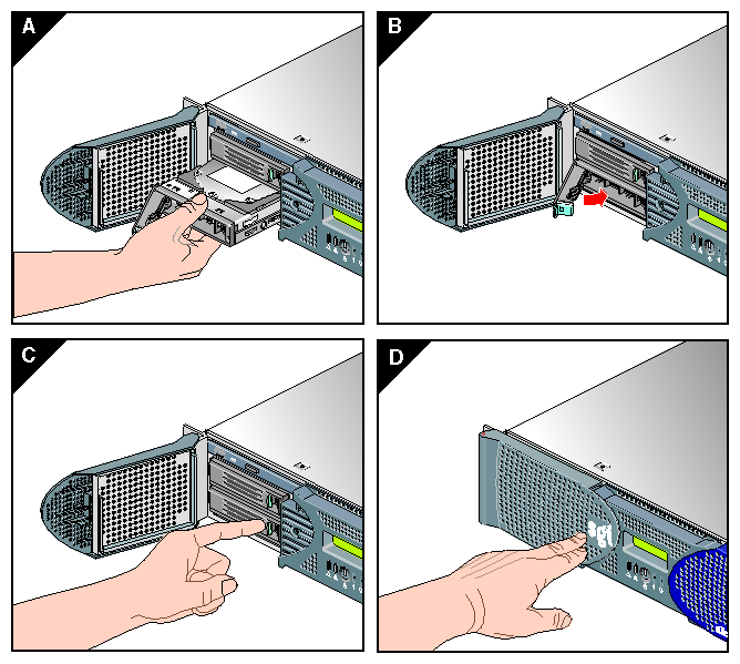
Each workstation enclosure can contain one or two sled-mounted Ultra 160 SCSI disk drives (see Figure 3-12). This section explains how to install and remove a disk drive.
| Note: The second enclosure in a dual-enclosure workstation must have an IO9 card in order to support disk drives. |

To install a disk drive, follow these steps:
Open the bezel door as far as it will open. Position the drive assembly so that it engages the bay guide rails and, with the locking handle fully swung open, gently push in the drive into the bay until the locking handle engages with left side of the bay opening as shown in Figure 3-13A.
Note: If you will have only one disk drive in your system, it should be located in the bottom–most slot. Swing the locking handle towards the chassis until the locking handle engages the latch as shown in Figure 3-13B and Figure 3-13C.
Close the bezel door as shown in Figure 3-13D.
To remove a disk drive, follow these steps:
If you are replacing a data drive, ensure that the drive has spun down before you remove it.
If you are replacing the system drive, you must first halt the operating system using a command such as /etc/shutdown or /etc/halt and then power off the system.
Open the bezel door located on the left side of the front panel of the enclosure as shown in Figure 3-14A. (Make sure that you open the door as far as it will open.)
Remove the drive by depressing the locking handle with your forefinger (see Figure 3-14B) and swing open the locking handle away from the chassis until the handle disengages the drive connector from the backplane connector (see Figure 3-14C).
Note: If you will have only one disk drive, it should be located in the bottom–most slot. Carefully slide the drive out of the bay (see Figure 3-14D) and gently place it on a flat ESD-safe surface. (Do not use the handle to pull the drive out of the bay.)
If you are replacing the disk drive, proceed to “Installing a Disk Drive”, for installation instructions. (After you have replaced the disk drive, return to step 8 for instructions to power on your system.) If you are not replacing the disk drive, proceed to the next step.
Close the bezel door.
Power on the system.

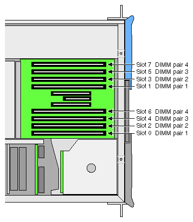
Memory is contained on cards that are referred to as DIMMs (dual inline memory modules). Each workstation enclosure can contain two, four, six, or eight DIMMs. The DIMMs are installed in eight slots located on the system node board.
These eight DIMM slots are organized into a group of even–numbered slots 0, 2, 4, and 6 and a group of odd-numbered slots 1, 3, 5, and 7, as shown in Figure 3-15.
DIMMs are installed one per DIMM slot, and two at a time, so that the two DIMMs installed provide local memory for the same pair of banks. For example, you can install a DIMM in slot 0 and another in slot 1 (this adds memory to bank pairs 0 and 1). Table 3-1 lists the DIMM slots and the corresponding bank pairs to which local memory is provided when DIMMs are installed:
Table 3-1. DIMMs and Bank Pairs
DIMM in Slot Number | Provides Local Memory for Bank Pair Numbers |
|---|---|
0[a] | 0 and 1 |
1 | 0 and 1 |
2 | 2 and 3 |
3 | 2 and 3 |
4 | 4 and 5 |
5 | 4 and 5 |
6 | 6 and 7 |
7 | 6 and 7 |
[a] The first two DIMMs must be installed in DIMM slot 0 and DIMM slot 1. | |
When installing DIMMs, you must follow these guidelines:
Memory is increased or decreased in two-DIMM increments only.
The two DIMMs that make up a bank pair must be the same memory size; however, each pair of DIMMs can be a different memory size from another pair.
The first two DIMMs must be installed in DIMM slot 0 and DIMM slot 1. Subsequent DIMM pairs can be installed in any order, but for consistency they should be installed in the next available DIMM slots.
The DIMMs used in the rack-mountable workstation are not compatible with the DIMMs used in Origin 200, SGI 2000 series, Onyx2, or Octane systems.
The workstation supports the following memory kits:
512-MB kit with integrated directory memory.
1-GB kit with integrated directory memory.
2-GB kit with integrated directory memory.
Caution: Electronic equipment can be irreparably damaged by electrostatic discharge (ESD). Always follow these preventive measures when you handle a system component:
- Remove a component from its antistatic bag only when you are ready to install it.
- If you handle a component before installation, do not place it on surfaces that produce ESD (carpeting, for example) or near devices that create static electricity.
- Attach a static wrist strap to a grounded connection on your system when you install or remove a component.
To install a DIMM, follow these steps:
Power off the system. For instructions on how to power off the system, see “Using the Workstation” in Chapter 1.
Disconnect all of the cables at the rear of the system.
Remove the two screws that secure the enclosure to the rear of the rack.
Warning: Components may be hot. To avoid injury, allow the components to cool for approximately 5 minutes before you proceed with these instructions. Remove the two screws that secure the enclosure to the front rails of the rack.
Using two people, pull the enclosure from the rack and move it to a tabletop or other sturdy work surface.
To access the DIMMs, remove the ten Phillips screws shown in Figure 3-16 and lift and open the hinged cover.
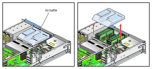
Remove the plastic air baffle covering the DIMMs as shown in Figure 3-17.
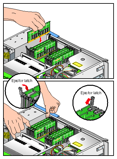
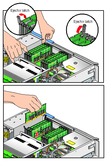
Install the DIMM, as follows (see Figure 3-18):
Open the ejector latches.
Hold the DIMM only by its edges and remove it from its antistatic package.
Align the three notches in the bottom edge of the DIMM with the keyed socket.
Insert the bottom edge of the DIMM into the socket, and then press down on the DIMM until it seats correctly. Use extreme care when you install a DIMM. If you apply too much pressure, you can damage the socket.
Gently push the plastic ejector latches down to secure the DIMM, as shown in Figure 3-18. When the DIMM is fully seated in the connector, the ejector latches snap into place.
Replace the plastic air baffle.
Attach the hinged cover and secure it to the with ten Phillips screws.
If your system is rackmounted, proceed to the next step. If your system is free-standing, proceed to step 15.
Slide the enclosure back into the rack.
Install the two screws that secure the enclosure to the front rails of the rack.
Install the two screws that secure the enclosure to the rear of the rack.
Reconnect all of the cables at the rear of the system.
Power on the system. For instructions on how to power on the system, see “Using the Workstation” in Chapter 1.
To remove a DIMM, follow these steps:
Power off the system. For instructions on how to power off the system, see “Using the Workstation” in Chapter 1.
Disconnect all of the cables at the rear of the system.
Remove the two screws that secure the enclosure to the rear of the rack.
Warning: Components may be hot. To avoid injury, allow the components to cool for approximately five minutes before you proceed with these instructions. Remove the two screws that secure the enclosure to the front rails of the rack.
Using two people, pull the enclosure from the rack and move it to a table top or other sturdy work surface.
To access the DIMMs, remove the ten Phillips screws shown in Figure 3-19 and open the hinged cover.
Remove the plastic air baffle covering the DIMMs as shown in Figure 3-20.
Remove the DIMM, as follows (see Figure 3-21):
Lift the two ejector latches simultaneously to disengage the DIMM from its connector.
Carefully grasp the DIMM and pull it up and out of the guide rails.
Note: Hold the DIMM only by its edges. Be careful not to touch its components or gold edge connectors. Place the DIMM on an ESD-safe surface.
Insert a new DIMM as described in “Installing a DIMM ”.
Replace the plastic air baffle.
Attach or close the hinged cover and secure it with the ten Phillips screws.
If your system is rackmounted, proceed to the next step. If your system is free-standing, proceed to step 15.
Using two people, slide the enclosure back into the rack.
Install the two screws that secure the enclosure to the front rails of the rack.
Reconnect all of the cables at the rear of the system.
Power on the system. For instructions on how to power on the system, see “Using the Workstation” in Chapter 1.
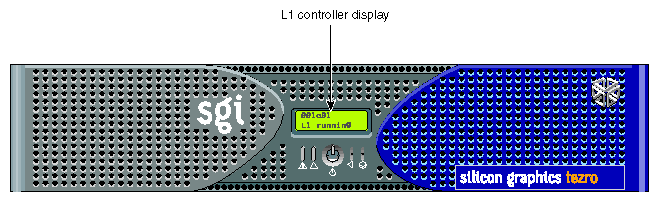
The L1 controller, which is used to monitor and manage the workstation, has a display located on the front panel as shown in Figure 3-22. Every workstation enclosure is factory shipped with an L1 controller display. This section describes how to replace an L1 controller display panel.
To replace an L1 controller display, follow these steps:
Power off the system. For instructions on how to power off the system, see “Using the Workstation” in Chapter 1.
Disconnect all of the cables at the rear of the system.
Warning: Components may be hot. To avoid injury, allow the components to cool for approximately five minutes before you proceed with these instructions. Remove the two screws that secure the enclosure to the front rails of the rack.
Using two people, pull the enclosure from the rack and move it to a tabletop or other sturdy work surface.
To access the area where the L1 display is replaced, remove the ten Phillips screws shown in Figure 3-23 and lift and open the hinged cover.
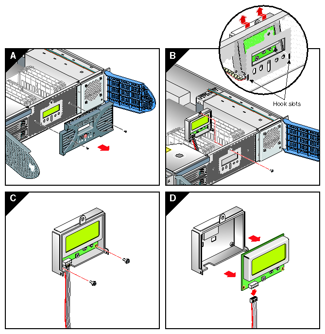
On the front panel of your system, remove the front bezel by unscrewing the two Phillips screws holding the bezel to the chassis, as shown in Figure 3-24A.
Holding the L1 display cover with one hand, unscrew the single Phillips screw holding the L1 display cover to the chassis, as shown in Figure 3-24B. Gently unhook and pull away the L1 display cover from the chassis.
Unscrew the two Phillips screws holding the L1 controller display panel to the L1 display protective cover, as shown in Figure 3-24C.
Gently disconnect the L1 controller cable from the connector on the L1 controller display, as shown in Figure 3-24D.
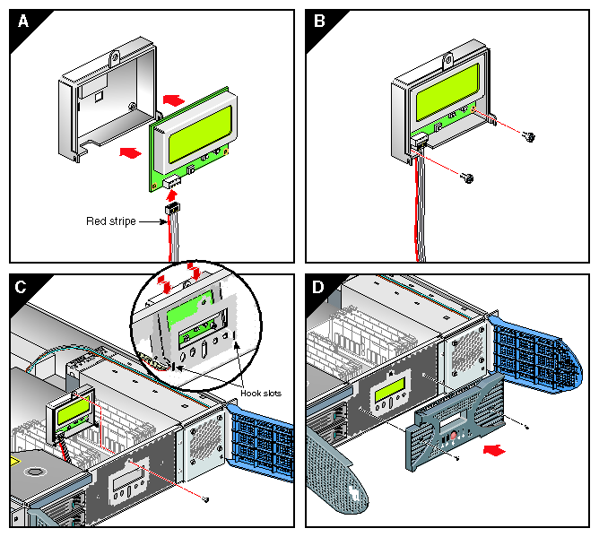
Connect the L1 controller cable to the connector on the new L1 controller display, making sure that the red stripe is to your left, as shown in Figure 3-25A.
Align the two screw holes on the L1 controller display with the holes on the L1 display protective cover, and screw in the two Phillips screws as shown in Figure 3-25B.
Hook the L1 display protective cover onto the slots on the front chassis, and holding the L1 display cover up against the front chassis, screw in the Phillips screw as shown in Figure 3-25C.
Replace the front bezel onto the front of the system by screwing in the two Phillips screws that hold the bezel to the chassis (see Figure 3-25D).
Attach the hinged cover and secure it to the enclosure with the ten Phillips screws.
If your system is rackmounted, proceed to the next step. If your system is free-standing, proceed to step 18.
Using two people, slide the enclosure back into the rack.
Install the two screws that secure the enclosure to the front rails of the rack.
Install all of the cables at the rear of the system.
Power on the system. For instructions on how to power on the system, see “Using the Workstation” in Chapter 1.
Each workstation enclosure contains one power supply (see Figure 3-26). This section provides the following information:
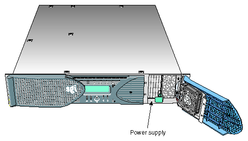
Use the LED located on the front (towards the top) of the power supply to read the condition of the power supply. Table 3-2 shows the LED status and the power supply condition the LED status indicates.
Table 3-2. LED Status and Power Supply Condition
LED Status | Power Supply Condition Indicated |
|---|---|
Off | This indicates that the power supply is not receiving AC power. Possible causes: the system is not plugged in correctly or a electrical fuse has blown. |
Amber | This indicates a fault condition for one of the following reasons: - The temperature limit has been exceeded. - The current limit has been exceeded. |
Blinking green | The power supply is receiving AC power, but the main primary DC power has not yet activated. |
Green | The power supply is operating properly. |
To replace the power supply, follow these steps:
Power off the system as described in the “Using the Workstation” in Chapter 1.
Remove the power supply as follows:
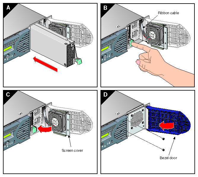
Swing open the bezel door located on the right side of the front panel. With a Phillips screw driver, unscrew the two screws on the screen cover as shown in Figure 3-27A.
Swing open the screen cover as shown in Figure 3-27B.
Disengage the power supply from the power supply bay by pushing the interior release button to the right and pulling up and out on the green–colored handle lock, as shown in Figure 3-27C.
Gently pull out the power supply from the chassis until it clears the power supply bay, as shown in Figure 3-27D. Place the power supply on an ESD-safe surface.
Caution: When pulling out the power supply from the chassis, make sure not to disturb the power supply fan's ribbon cable.
Install the replacement power supply, as follows:
Position the power supply in the slot and with the power supply handle pulled up (fully opened), gently push the power supply into the bay as shown in Figure 3-28A.
Caution: When installing the power supply, make sure that the power supply does not clip or pinch the power supply fan's ribbon cable. Push in and down on the green–colored handle and snap the power supply into place as shown in Figure 3-28B.
After you have installed the power supply, swing the screen cover until it closes as shown in Figure 3-28C.
Caution: When closing the screen cover, make sure that the cover does not clip or pinch the power supply fan's ribbon cable. Screw in the two Phillips screws that you had removed as shown in Figure 3-28D, and close the bezel door.
Power on the system, as described in the “Using the Workstation” in Chapter 1.