This addendum describes the function and physical components of the PX–brick, which is used to connect I/O devices to your system. It also describes how to install and replace a PCI or PCI–X card in the PX–brick. Specifically, it includes the following information:
This addendum is a supplement to the following documentation:
SGI Origin 3000 Series Owner's Guide (007-4240-00X)
SGI Onyx 3000 Series Graphics System Hardware Owner's Guide (007-4264-00X)
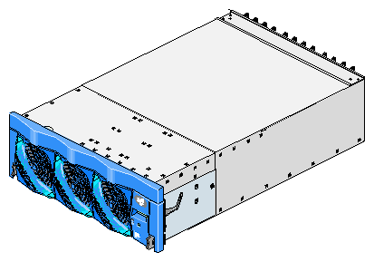
The 4–U high PX–brick shown in Figure 1 provides 12 card slots to support up to 12 PCI or PCI–X cards. The 12 slots are configured as six 2–slot buses.
When compared to the P–brick, the PX–brick offers the following enhancements:
The PX–brick supports both PCI cards and PCI–X cards. PCI–X cards enable I/O devices to work more efficiently, which increases the sustained I/O bandwidth.
The PX–brick can connect an InfiniteReality graphics pipe to a compute brick.
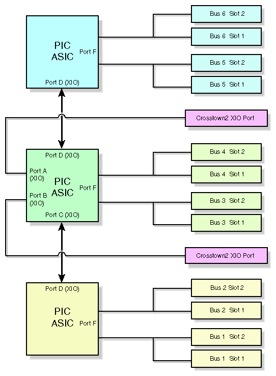
Three PIC (PCI interface chip) ASICs are key components of the PX–brick architecture. The PIC ASICs support the following (see Figure 2):
This section describes the external components located on the front and rear panels of the PX–brick.
The following are the front panel components of the PX–brick (see Figure 3):
L1 controller and display. The L1 controller generates PX–brick status and error messages that appear on the liquid crystal display (LCD).

Note: For more information about the L1 controller, see the SGI L1 and L2 Controller Software User's Guide. On/Off switch with LED. Press this button with the green LED to turn on the internal components. Alternatively, you can turn on the internal components at an L2 controller display or at a system console.
LEDs:
On/Off switch LED. This green LED lights when the internal components of the PX–brick are on, and it turns off when they are off.
Service required LED. This LED lights yellow to indicate that a component is broken or is not operating properly (for example, if a fan is off) but the PX–brick is still operating.
Failure LED. This LED lights red to indicate that a system failure has occurred and the PX–brick is not operating.
Fans. You have three hot–swappable fans to provide the required cooling for your PX–brick.

Warning: To prevent personal injury, or damage to the PX–brick, the hot-swappable fans can be installed only by a trained SGI system support engineer (SSE).

Figure 4 shows the location of the rear panel components of the PX–brick.
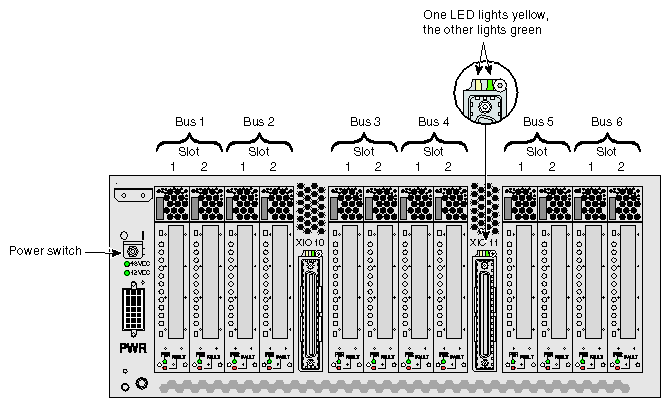
The rear panel has the following items:
Power switch. Moving the power switch to the I position powers on the L1 controller of the PX–brick, and moving it to the 0 position powers off the L1 controller. Powering on the L1 controller lights the 12–VDC green LED.
12–VDC LED. The 12–VDC green LED lights when the L1 controller is powered on and operating. The L1 controller is powered on by turning on the power switch.
48–VDC LED. The power switch must be in the ON (I) position for this LED to light. This green LED lights when the rest of the PX–brick internal components are powered on and operating. The rest of the internal components are powered on by pressing the On/Off switch located on the front panel of the brick. (The green LED on the On/Off switch lights when you power on the internal components.) These internal components can also be powered on via the L2 controller touch display or the system console.
Power connector. This connector (labeled PWR) connects the PX–brick to the power bay to give power to the PX-brick.
PCI/PCI–X slots. Use these slots to install or replace PCI or PCI–X cards in your system. See “Installing PCI and PCI–X Cards”. The card slots are numbered bus 1 through bus 6. Each bus has two slots, labeled 1 and 2, as shown in Figure 4.
Power LED. This LED (labeled PWR) lights green when the PCI card carrier is installed securely and is getting power.
Fault LED. This LED lights yellow when a fault occurs with the PCI or PCI–X card.
XIO 10 and XIO 11 connectors. Each connector can connect the PX–brick to one compute brick. As an option, the second connector can be connected to another compute brick to create a dual-ported PX–brick, which would provide greater bandwidth.
XIO 10 and XIO 11 connector LEDs. Each connector has an LED that lights yellow and an LED that lights green. One LED lights yellow to indicate that both the PX–brick and the compute brick to which it is connected are powered on. The other LED lights green when the PX–brick link to the compute brick is established.
The PCI and PCI–X card slots on the motherboard are numbered bus 1 through bus 6. Each bus has two slots, labeled 1 and 2, as shown in Figure 5. Separate buses enable the PX–brick to run cards of different frequencies at the same time. As a result, the same PX–brick can run 133–MHz, 100–MHz, 66-MHz, and 33–MHz cards at the same time.
The PCI/PCI–X bus supports 32-bit and 64-bit PCI or PCI–X cards at the same time.
For maximum bandwidth, PCI/PCI–X cards are distributed across all six buses when they are integrated at the factory.

To maximize the operating efficiency of PCI and PCI-X cards, you must consider the following during installation:
Although you can install a PCI and a PCI-X card in the same bus at the same time, and install cards of different frequencies (for example, 33-MHz and 66-MHz cards) in the same bus at the same time, you should avoid doing so for the following reasons:
If you have a PCI card and a PCI-X card in the same bus at the same time, both cards will operate in PCI mode, thereby losing the capability of the PCI-X card.
If you have two cards of different speeds in the same bus, both cards will operate at the lower speed. For example, if you have a 66-MHz and a 33-MHz card in the same bus, both cards will run at 33 MHz.
To obtain optimum function from your cards, it is recommended that you install PCI and PCI-X cards in a bus in one of the following configurations:
One 133-MHz PCI-X card at 133 MHz.
Two 133-MHz PCI-X cards at 100 MHz.
Two 66-MHz PCI-X cards.
Two 66-MHz PCI cards.
Two 33-MHz PCI cards.
If you need to change the mode or speed (MHz) of a bus to replace a card with a card of a different mode or speed, you must power off the PX-brick, install the replacement card, and then power on the PX-brick.
PCI and PCI-X cards for which the system has the certified device drivers are hot-pluggable. (Contact your service representative to identify which cards are supported by certified device drivers.) If you are installing a hot-pluggable card, power off only the individual card slot in which you will add or replace the card, not the entire rack or PX–brick. Power off and power on the card slot with the pciconfig IRIX command. For details on using this command, type man pciconfig on your system console or see IRIX Admin: System Configuration and Operation.
Note: PCI and PCI–X cards are hot-pluggable only in systems running IRIX operating system software. You cannot hot–plug PCI or PCI–X cards in systems running Linux operating system software. If you are installing a card that is not hot-pluggable, you need to shut down the operating system, power off the PX–brick, install or replace the card, power on the PX-brick, and then boot the operating system.
SGI supports various PCI and PCI–X cards. These cards can be purchased from SGI or another manufacturer. Ask your SGI sales representative for a current listing of PCI and PCI–X cards supported by SGI.
Each PCI or PCI–X card is mounted on a carrier so that you can slide the card into and out of the brick. This carrier, which can be adjusted to accommodate cards of different sizes, is designed to support most PCI and PCI–X cards. (To learn how to adjust a carrier, see the next section.)
When the PX–brick is shipped, any card that was ordered is installed with a carrier, and any unoccupied slot is populated with an empty carrier. A carrier must be present in an unpopulated slot to maintain an even airflow through the slot and to protect against electromagnetic interference (EMI).
This section provides step-by–step instructions on how to add or replace a PCI or PCI–X card in the PX–brick. To maximize the operating efficiency of your cards, make sure that you have read all the introductory matter in “Installing PCI and PCI–X Cards” before beginning the installation.
| Warning: Before installing, operating, or servicing any part of this product, read the “Safety Instructions” section in the “Regulatory Specifications and Safety Information” appendix in your SGI Origin 3000 Series Owner's Guide or SGI Onyx 3000 Series Graphics System Hardware Owner's Guide. |
 | Caution: It is recommended that you use a grounding wrist strap while installing a PCI or PCI–X card. |
To add or replace a PCI or PCI–X card, follow these steps:
If the PCI or PCI-X card is hot–pluggable (if the system has a certified device driver for the card and is running IRIX operating system software), use the pciconfig IRIX command to power off the card (the slot) in which you will add or replace the card. (For details on using the pciconfig command, type man pciconfig on your system console or see IRIX Admin: System Configuration and Operation.) Then proceed to step 2.
If the card is not hot-pluggable (if it does not have the required certified device driver or if the system is running Linux operating system software), or if you are replacing a hot–pluggable card with a card of a different speed, follow these steps:
Shut down your operating system software. (See your software operation guide if you need instructions for shutting down the operating system.)
Power off the PX–brick by following the power–off instructions in the power-off section of your SGI Origin 3000 Series Owner's Guide or SGI Onyx 3000 Series Graphics System Hardware Owner's Guide.
Pull the seating bar on the selected card carrier straight out to extract it from a slot, as shown in Figure 6.
If you are replacing a card, gently pull the existing card from the carrier. If you are adding a card, extract the carrier metal filler plate by pushing down on it, as shown in Figure 7. This filler plate covers the area where your card connectors will protrude out to the rear panel of the PX–brick.
If the card you want to install does not fit the carrier, loosen the three screws on the guide bar with a Phillips screwdriver (if your carrier uses T8 Torx screws, you will need a Torx screw driver) and adjust the carrier guide bar (also known as the alignment rail) up or down as necessary (see Figure 8).
Mount the card in the carrier, as shown in Figure 9, so that the following occurs:
The card connectors protrude through the bulkhead where the metal filler plate was located.
The edge connectors fit between the bottom guides of the carrier.
The top of the card fits under the clips on the guide bar.
Tighten the three screws on the guide bar if necessary.
If you want to install a half-height PCI card, do the following to secure the card to the carrier (if you are not installing a half-height PCI card, proceed to step 6):
Remove the two screws (T8 Torx screws or Phillips screws) from the carrier guide bar, as shown in Figure 10.
Note: Be careful not to lose the threaded inserts in the carrier guide bar. Loosen the third screw of the carrier guide bar.
Place the half-height PCI card in the carrier so that the connector edge of the card rests against the lower guide tab of the carrier (see Figure 10).
Move the carrier guide bar (adjustment rail) so that it holds the card firmly in place (see Figure 11).
Place the PCI card bracket so that the screw holes of the bracket align with the empty screw holes of the carrier guide bar, as shown in Figure 12.
Secure the bracket to the carrier guide bar with two T8 Torx screws.
Insert the carrier that carries the card into the vacant slot, using the slot guide, as shown in Figure 13.
Push horizontally on the seating bar, as shown in Figure 14, to seat the card securely in the slot.
If the card is hot–pluggable, power on the card (slot) using the pciconfig IRIX command, and then proceed to step 9. (For details on using the pciconfig command, type man pciconfig on your system console or see IRIX Admin: System Configuration and Operation.) If the card is not hot-pluggable, power on the brick as follows:
Note: The PCI and PCI–X card slots are not hot–pluggable in systems running Linux operating system software. Power on the PX–brick by following the power–on instructions in the power-on section of your SGI Origin 3000 Series Owner's Guide or SGI Onyx 3000 Series Graphics System Hardware Owner's Guide.
Boot your operating system software. (See your software operation guide if you need instructions to boot your operating system.)
Run the hinv hardware inventory command to verify the installation. This command lists hardware that the operating system discovered during the boot operation.
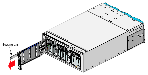
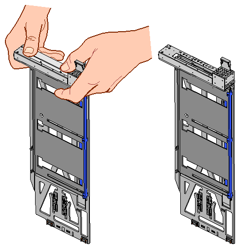
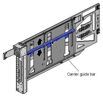
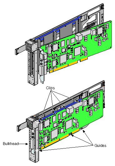
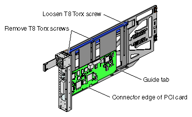
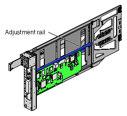
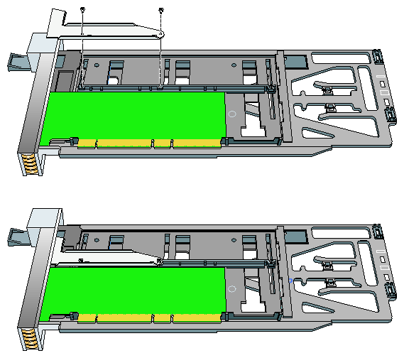
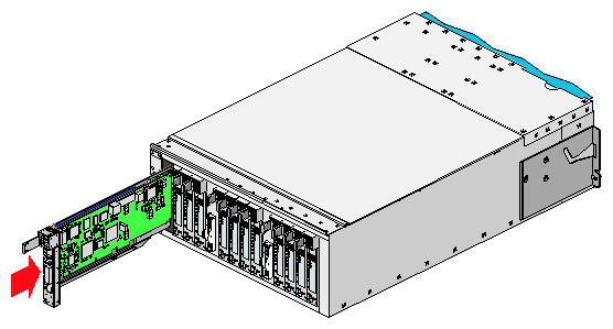
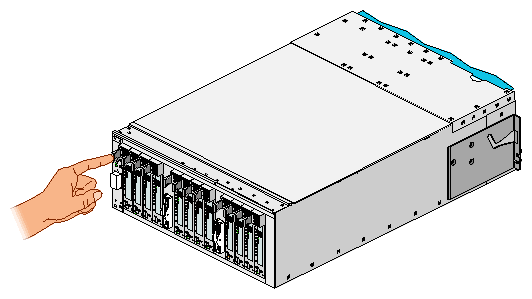
Table 1 lists the physical specifications of the PX-brick.
Table 1. Physical Specifications of PX–brick
Characteristic | Specification |
|---|---|
Height | 7.0 in. (177.8 mm) |
Width | 17.5 in. (444.5 mm) |
Depth | 27.5 in. (698.5 mm) |
Weight | 60 lb (27.3 kg) |
Input power | +48 VDC |
©2003, Silicon Graphics, Inc. All rights reserved.
Silicon Graphics, SGI, the SGI logo, IRIX, InfiniteReality, Onyx, and Origin are registered trademarks of Silicon Graphics, Inc. Linux is a registered trademark of Linus Torvalds.