This addendum describes the functions, features, physical components, technical specifications, and system configurations for the Cx–brick. This information is covered in the following sections:
This addendum is a supplement to the following documentation:
SGI Origin 3000 Series Owner's Guide (007-4240-00X)
SGI Onyx 3000 Series Graphics System Hardware Owner's Guide (007-4264-00X)
The Cx–brick (shown in Figure 1) is a combination high-density processor and router that provides enhanced performance at a lower cost and with less physical space requirements than existing C–brick with R–brick configurations. A Cx–brick, which is equivalent to the functionality of four C–bricks and one R–brick, can be configured to provide four times the density of the current SGI Origin 3000 server or SGI Onyx 3000 graphics system.
As many as eight Cx–bricks can be placed in an SGI 3000 rack, providing up to 128 processors and 256 GB of memory per rack.

The Cx–brick has the same modular features of the current SGI 3000 series bricks and is fully compatible with the SGI 3000 series architecture. The Cx–brick has the following features:
Contains an L1 controller to monitor and manage the function of the Cx–brick. This L1 controller can be connected, monitored, and managed with L2 controllers.
Rack–mountable in an Origin 3000 series server or Onyx 3000 series graphics system rack.
Uses Bedrock and router ASICs (application–specific integrated circuits) that are compatible with the Origin 3000 series servers and Onyx 3000 series of graphics systems.
Receives power from a power bay and converts it to the voltages required by the Cx–brick.
Supports MIPS processors.
Compatible with SGI's current graphics product line offerings: InfiniteReality graphics (G–brick), and InfinitePerformance graphics (V-brick).
Compatible with all current I/O bricks such as I–brick, P–brick, X–brick, N–brick, IX–brick, PX–brick, and all future I/O bricks.
Uses the IRIX operating system (versions 6.5.18, or later).
Table 1 lists some of the differences between the Cx–brick and the C-bricks and R-bricks, indicating some of the advantages of the Cx–brick.
Table 1. Comparing Cx–brick with C–brick and R–brick
Characteristic | Cx-brick | C-brick | R-brick |
|---|---|---|---|
Processors | Zero to 16 | 2 or 4 | N/A |
Processor boards | 4 IP53 node boards | 2 PIMMs | N/A |
Memory | 1 GB to 32 GB | 1 GB to 8 GB | N/A |
DIMMs | 8 per node board | 8 per brick | N/A |
NUMAlink ports | 4 internal and 4 external | 1 external | 8 external |
XIO ports | 4 internal and 4 external | 1 external | Zero |
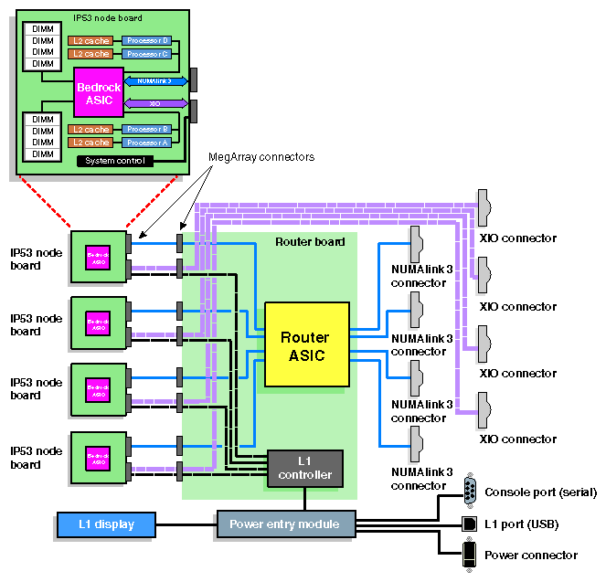
The Cx–brick architecture includes the following components shown in Figure 2 and discussed in the following subsections:
-

Warning: To prevent personal injury, or damage to your system, only trained SGI system support engineers (SSEs) can service the internal components of the Cx–brick.
The Cx–brick includes one to four processor boards known as IP53 node boards. The Cx–brick supports two types of IP53 node boards, as follows:
Four-processor node board that has 8 MB of L2 cache per processor and up to eight DIMMs.
Zero-processor node board that has up to eight DIMMs (no L2 cache) to serve as a memory node.
Each IP53 node board has the following components:
Bedrock application–specific integrated circuit (ASIC) that enables communication between the various system devices.
Zero or four processors (labeled A, B, C, and D).
One L2 cache for each processor to reduce memory latency.
Two MegArray connectors (one XIO and one NUMAlink 3) to connect the IP53 node board to the router board.
Up to eight dual–inline memory modules (DIMMs).
Each IP53 node board in a Cx–brick can have from 1 GB to 8 GB of local memory, which includes main memory and directory memory for cache coherence. Local memory comes in DIMMs that contain double data rate synchronous dynamic random-access memory (DDR SDRAM).
The Cx–brick supports 512 MB and 1 GB single DIMM sizes (see Table 2).
Table 2. Memory DIMM Specifications
Memory Kit
Single DIMM Size
DDR SDRAM Technology
1 GB with premium integrated directory memory
512 MB
128 Mbits
2 GB with premium integrated directory memory
1 GB
256 Mbits
Your SGI support service engineer (SSE) can increase or decrease the size of memory by adding or removing the DIMMs, which must be added or removed in DIMM pairs.
The Cx–brick includes a router board, which has the same function as the R–brick. The router board is a single printed circuit board (PCB) that contains the following:
Router ASIC (same ASIC as used in the R–brick) that makes up the NUMAlink 3 interconnect that routes messages between the compute nodes in the system.
Four NUMAlink 3 connectors. Two connectors connect to another Cx–brick; one connector connects to an R–brick (router), and another connector connects to a different R–brick.
Two internal XIO connectors. Each internal XIO connector connects to a separate XIO jumper board. Each XIO jumper board has two external XIO connectors providing a total of four external XIO connectors for the Cx-brick.
One 48V-to-2.5V converter for the router ASIC.
One L1 controller, which is used to monitor and manage your Cx–brick, generates status and error messages that appear on the liquid crystal display (LCD) located on the Cx–brick front panel (see Figure 3). You can also use your system console to monitor and manage your system and to enter L1 controller commands. For detailed information about the L1 controller and L2 controller commands, see your SGI L1 and L2 Controller Software User's Guide.
Four sets of MegArray connectors (one XIO and one NUMAlink 3 connector per set). Each set of connectors connects to a separate IP53 node board.
The Cx-brick contains a power entry module (also known as the inlet board) that receives 48 VDC power from the power bay and converts it to 12 VDC (for the node boards). The power entry module, which controls fan speed, also contains the following items:
Four sets of 48V-to-12V converters (one set for each IP53 node board).
Power switch to power on and power off the Cx–brick.
Power connector to connect the Cx–brick to the power bay to give power to the Cx–brick.
Console serial port (DB-9) connector for the system console connection.
L1 port (USB) connector for the L1–to–L2 controller connection.
Connector that connects the power entry module to the L1 display.
Eight power LEDs (described in “Rear Panel Components”).
This section describes the Cx–brick external components, which are located in the brick front and rear panels.
The following are the front panel components of the Cx–brick (see Figure 3):
L1 controller and display. The L1 controller generates Cx–brick status and error messages that appear on the liquid crystal display (LCD).
On/Off switch with LED. Press this button to turn on and off the Cx–brick internal components. Alternatively, you can turn on and off the Cx–brick internal components at an L2 controller touch display or at a system console.
LEDs:
On/Off switch LED. This green LED lights when the Cx–brick internal components are on and turns off when they are off.
Service required LED. This LED lights yellow to indicate that a component is broken or not operating properly (for example, if a fan is off), but the Cx–brick is still operating.
Failure LED. This LED lights red to indicate that a system failure has occurred and the Cx–brick is not operating.
Reset switch. Press this switch to reset the Cx–brick internal processors and ASICs. The reset will cause a memory loss. (See the non-maskable interrupt [NMI] to perform a reset without losing memory.)
Non-maskable interrupt (NMI) switch. Press this switch to reset the Cx–brick internal processors and ASICs without losing memory.
Fans. The system has three hot–swappable fans to provide the required cooling for the Cx–brick.
Warning: To prevent personal injury, or damage to the Cx–brick, the hot-swappable fans can be installed only by a trained SGI system support engineer (SSE).
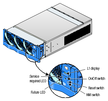
Figure 4 shows the location of the rear panel components on the Cx–brick.
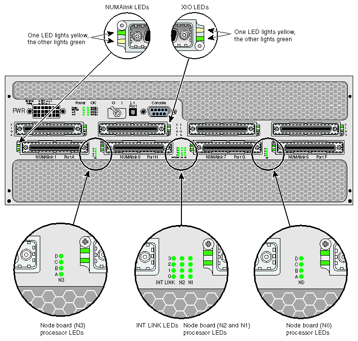
The Cx–brick rear panel has the following items:
Power switch. Moving the power switch to the I position powers on the Cx–brick L1 controller, and moving it to the 0 position powers off the L1 controller. Powering on the L1 controller lights the 12–VDC green LED (labeled 12 V).
PWR (power) connector. This connects the Cx–brick to the power bay to give power to the Cx–brick.
Eight power LEDs:
12–VDC LED. This green LED (labeled 12 V) lights when the L1 controller is powered on and operating. You can power on the L1 controller by turning on the power switch.
48–VDC LED. This green LED (labeled 48 V) lights when the power switch is ON (I) position and when the rest of the Cx–brick internal components are powered on and operating. You power on the rest of the internal components by pressing the On/Off switch located on the front panel of the brick. (The green LED on the On/Off switch lights when you power on the internal components.) You can also power on these internal components via the L2 controller touch display or the system console.
Router LED. This green LED lights when the router board is receiving the required power.
One LED for each IP53 node board (labeled NODE 0, NODE 1, NODE 2, and NODE 3). Each green LED lights when the corresponding node board is receiving the required power.
Inlet Brd LED. This green LED lights when the inlet board (also known as the power entry module) is receiving the required power.
Four XIO connectors. These connectors are labeled (from left to right): XIO 2, XIO 1, XIO 3, and XIO 0. Each of these connectors corresponds to a separate IP53 node board: XIO 2 to node 2, XIO 1 to node 1, XIO 3 to node 3, and XIO 0 to node 0. These Crosstown 2 connectors are used to connect the Cx–brick to I/O bricks and graphics bricks in the system.
XIO connector LEDs. Each XIO connector has an LED that lights yellow and an LED that lights green. One LED lights yellow to indicate that both the Cx–brick and the I/O brick or graphics brick to which it is connected are powered on. The other LED lights green when the Cx–brick link to the I/O brick or graphics brick is established.
Four NUMAlink 3 connectors. These connectors are labeled from left to right, as follows: NUMAlink 1 Port A, NUMAlink 8 Port H, NUMAlink 7 Port G, and NUMAlink 6 Port F. Each connector connects the Cx–brick to another Cx–brick or a router (R–brick) in the system. Ports A and F connect to a single Cx–brick, and Ports G and H each connect to a separate R–brick.
NUMAlink 3 LEDs. Each NUMAlink 3 connector has an LED that lights yellow and an LED that lights green (located to the left of each NUMAlink 3 connector). One LED lights yellow to indicate that the Cx–brick and the Cx–brick or R–brick (router) to which it is connected are powered on. The other LED lights green when the link between the Cx–brick and the brick to which it is connected is established.
Node board processor LEDs. Each IP53 node board has four LEDs, one for each possible processor, that are labeled (from bottom to top) A, B, C, and D. These sets of four LEDs, which are located between the NUMAlink 3 connectors, are labeled (from left to right) N3, N2, N1, and N0. (Even though node boards N2 and N1 only have the lowermost processor (A) and topmost processor (D) LEDs labeled, the LEDs are positioned in the same order as they are for N3 and N0.) These heartbeat LEDs light orange to indicate that a processor is operating properly.
INT LINK LEDs. This set of four LEDs, labeled 0, 1, 2, and 3 indicates the status of the internal NUMAlink 3 connections between the processor node boards 0, 1, 2, and 3 and the router. These LEDs light green to indicate that a connection is operating properly. The LEDs light only if a link connection has been established.
Console connector. This is a DB-9 RS-232 port (console and diagnostic port) connector that connects the Cx–brick L1 controller to a system console. The Cx–brick L1 controller communicates with a system console through the console connector, which provides a serial bus that uses standard RS-232 protocol.
L1 Port connector. This universal serial bus (USB) connector connects the Cx–brick L1 controller to the L2 controller.
Table 3 lists the physical specifications of the Cx–brick.
Table 3. Cx-brick Physical Specifications
Characteristic | Specification |
|---|---|
Height | 7.0 in. (177.8 mm) |
Width | 17.5 in. (444.5 mm) |
Depth | 27.5 in. (698.5 mm) |
Weight | 70 lb (31.75 kg) |
Input power | +48 VDC (approx. 1100–W DC) |
Table 4 lists the specifications of the Cx–brick ports.
Table 4. Cx-brick Port Specifications
Port | Quantity | Specification |
|---|---|---|
NUMAlink 3 | 4 | 1.6 GB/s each direction (3.2 GB/s full duplex) |
XIO | 4 | 1.2 GB/s each direction (2.4 GB/s full duplex) |
Console | 1 | DB-9 connector |
L1 port | 1 | USB type B |
Power entry | 1 | 21–pin Foxcon |
This section lists the Cx–brick internal brick configurations such as which IP53 boards (how many processors in boards) can work together within the brick.
This section also lists external Cx–brick configurations. It shows a sample Origin 3000 server configuration with Cx–bricks, and two sample Onyx 3000 graphics system configurations with Cx–bricks.
IP53 node boards, and the processors, cache, and DIMMs on these node boards, are the configurable internal components of the Cx–brick.
| Warning: To prevent personal injury, or damage to your system, only trained SGI system support engineers (SSEs) can service or configure the internal components of the Cx–brick. |
The following are some configuration rules you must keep in mind when deciding to order a change in the internal configuration of your Cx–brick:
 | Note: Ask your SGI sales or service representative for help in ordering an internal component configuration change to your Cx–brick. |
Although a Cx–brick can include up four node boards, it does not have to be fully populated with node boards.
A Cx–brick can include IP53 node boards with different quantities of processors, cache, and DIMMs. The node board types include the following:
Four-processor node board with 8 MB of L2 cache for each processor and up to 8 DIMMs.
Zero-processor node board with no L2 cache and up to 8 DIMMs.
Processors scale in increments of four.
Processor speed must be the same for each IP53 node board.
Memory increases in two–DIMM increments.
The Cx–brick uses Origin 3000 series DIMMs.
Each IP53 node board requires a minimum of two DIMMs that must reside in DIMM slots 0 and 1.
The two DIMMs that compose a bank pair must be the same size; however, the DIMMs in another type of DIMM pair can differ in memory size.
The Cx–brick supports various system configurations to serve your computing needs as a part of an Origin 3000 server and as part of an Onyx 3000 graphics system. For example, the Cx–brick can connect to up to four I/O bricks via its XIO port connectors. The Cx–brick also has four NUMAlink 3 connectors. Two connectors connect to another Cx–brick; one connector connects to an R–brick (router), and another connector connects to a different R–brick.
This section shows a sample Origin 3000 server configuration with Cx–bricks and two sample Onyx 3000 graphics systems with Cx–bricks.
Figure 5 shows a 256–processor Origin 3000 server system configuration in three racks that includes the following:

Figure 6 shows a 32–processor Onyx 3000 graphics system configuration with InfiniteReality graphics pipes in three racks that includes the following:
Two Cx–bricks (16 processors in each brick).
Five G–bricks housing a total of eight InfiniteReality graphics pipes (five with four Raster Manager (RM) boards, and three with two RM boards).
Two N–bricks to connect the InfiniteReality graphics pipes to the Cx–bricks.
One I–brick for base I/O functionality.
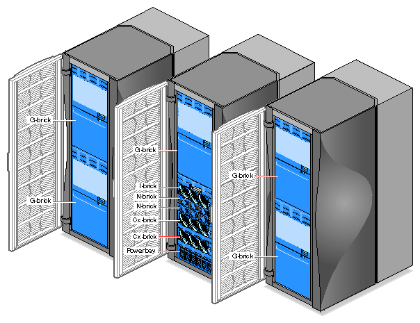
Figure 7 shows a 32–processor Onyx 3000 graphics system configuration with InfinitePerformance graphics pipes in a single rack that includes the following:
Two Cx–bricks (16 processors in each brick).
Three V–bricks housing a total of six InfinitePerformance graphics pipes (three pipes, each of which has two VPro V12 boards).
Three Scalable Graphics Compositors, which are used to combine two or four DVI digital video inputs into a single video output to increase graphics performance.
One I–brick for base I/O functionality.

This section lists the pin assignment information for the Cx–brick console connector and the L1 port connector. Both of these are non–proprietary connectors.
Figure 8 shows the pin assignments for the console connector. The console connector is a DB-9 RS-232 port (console and diagnostic port) connector that connects the Cx–brick L1 controller to a system console. The Cx–brick L1 controller communicates with a system console through the console connector, which provides a serial bus that uses standard RS-232 protocol.
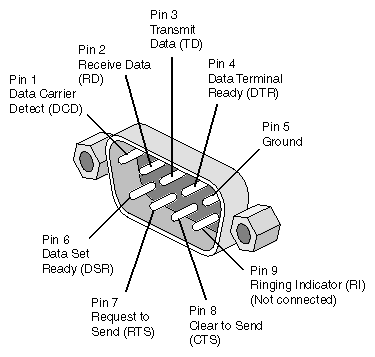
Figure 9 shows the pin number locations for the L1 port Universal Serial Bus (USB type B) connector. This connector connects the Cx–brick L1 controller to the L2 controller. Table 5 lists the pin assignments for the USB type B connector.
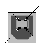
Table 5. USB Type B Connector Pin Assignments
Signal | Color | Pin Number |
|---|---|---|
VCC | Red | 1 |
-Data | White | 2 |
+Data | Green | 3 |
Ground | Black | 4 |