This addendum provides pin assignment information for the non-proprietary connectors on the SGI Origin 300 server, SGI Onyx 300 graphics system, L2 controller, NUMAlink module, SGI Total Performance 900 (TP900) storage module, and USB hub devices that are described in the following documentation:
SGI Origin 300 User's Guide (007-4365-001)
SGI Origin 300 System with NUMAlink Module User's Guide (007-4498-001)
SGI Onyx 300 Graphics System User's Guide (007-4509-001)
Table 1 describes the pin assignments for the connectors located on the rear panel of the SGI Origin 300 server and the SGI Onyx 300 graphics system shown in Figure 1.
Table 1. SGI Origin 300 Server and SGI Onyx 300 Graphics System Connectors
Connector | Connector Type | Pin Assignments |
|---|---|---|
Serial ports 1 and 2 | DB9 | See Figure 6
|
L1 console port | DB9 | See Figure 7
|
Ethernet port | RJ-45 | See Figure 8
|
External SCSI port | SCSI 68-pin VHDCI | See Figure 9 and Table 4
|
RT interrupt input and output | Stereo jack | See Figure 10 and Table 5
|
USB ports 1 and 2 | USB type A | See Figure 11 and Table 6
|
USB L1 port | USB type B | See Figure 12 and Table 7
|
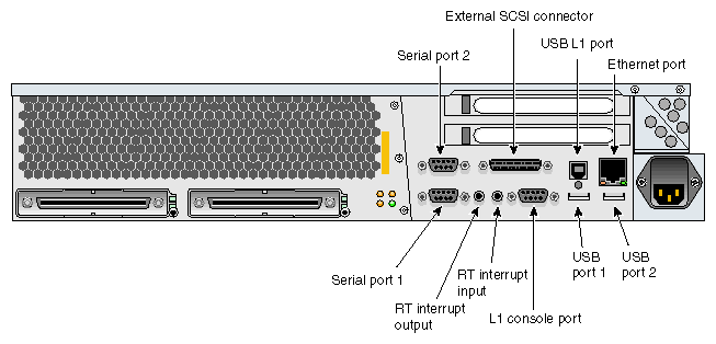
Table 2 describes the pin assignments for the port connectors located on the rear panel of the L2 controller shown in Figure 2.
Table 2. L2 Controller Connector Pin Assignments
Connector | Connector Type | Pin Assignments |
|---|---|---|
Console (serial port) | DB9 | See Figure 7
|
Modem (serial port) | DB9 | See Figure 7
|
Ethernet port | RJ-45 | See Figure 8
|
L1 ports (four ports) | USB type A | See Figure 11 and Table 6
|

Figure 3 shows the L1 port (USB type B) connector located on the rear panel of the NUMAlink module. Figure 12 shows the pin number locations for the USB type B connector, and Table 7 shows the pin assignments.
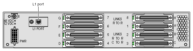
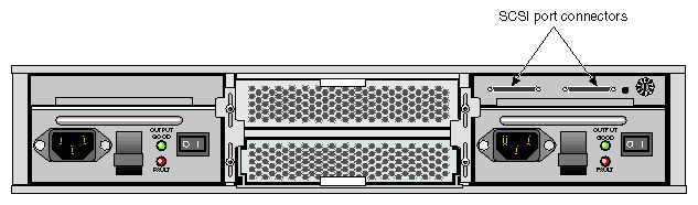
Figure 4 shows the two SCSI port connectors located on the rear panel of the TP900 storage module. Figure 9 shows how the pin numbers are distributed on the SCSI connector, and Table 4 shows the pin assignments.
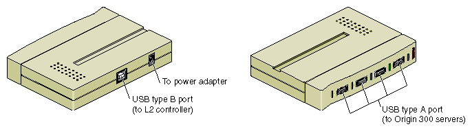
This section discusses the pin assignments for the five USB port connectors on the USB hub. These USB ports connect the L2 controller to SGI Origin 300 servers.
One USB type B port connects to the L2 controller, and the other four USB type A ports are used to connect to the Origin 300 servers as shown in Figure 5. Figure 11 shows the pin number locations for the USB type A port connectors, and Table 6 shows the pin assignments. Figure 12 shows the pin number locations for the USB type B port connectors, and Table 7 shows the pin assignments.
This section provides the pin assignments for the connectors listed in Table 3.
Table 3. Connector Pin Assignments
Connector Type | Connectors | Pin Assignments |
|---|---|---|
DB9 connector | Serial port 1 and serial port 2 on the SGI Origin 300 server and SGI Onyx 300 graphics system. | See Figure 6
|
DB9 connector (pin 9 not connected) | L1 console port on the SGI Origin 300 server and SGI Onyx 300 graphics system; console port and modem port on the L2 controller. | See Figure 7
|
RJ-45 connector | Ethernet port on the SGI Origin 300 server, SGI Onyx 300 graphics system, and L2 controller. | See Figure 8
|
SCSI connector | The External SCSI on the SGI Origin 300 server, SGI Onyx 300 graphics system, and TP900. | See Figure 9 and Table 4
|
Stereo jack connector | RT interrupt input and output ports on the SGI Origin 300 server and SGI Onyx 300 graphics system. | See Figure 10 and Table 5
|
USB type A connector | USB port 1 and USB port 2 on the SGI Origin 300 server and SGI Onyx 300 graphics system; four L1 ports on the L2 controller; four USB ports on the USB hub. | See Figure 11 and Table 6
|
USB type B connector | USB L1 port on the SGI Origin 300 server and SGI Onyx 300 graphics system; L1 port on the NUMAlink module; USB port on the USB hub. | See Figure 12 and Table 7
|
Figure 6 shows the DB9 connector pin assignments for the serial port 1 and serial port 2 located on the rear panel of the SGI Origin 300 server and SGI Onyx 300 graphics system.
Figure 7 shows the DB9 connector pin assignments for the L1 console port on the SGI Origin 300 server and SGI Onyx 300 graphics system and for the console and modem ports located on the rear panel of the L2 controller.
 | Note: The pin assignments for the L1 console port, console port, and modem port are different from the pin assignments for the serial port 1 and serial port 2 because Pin 9 of the L1 console port, console port, and modem port is not connected. |
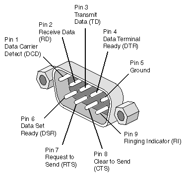
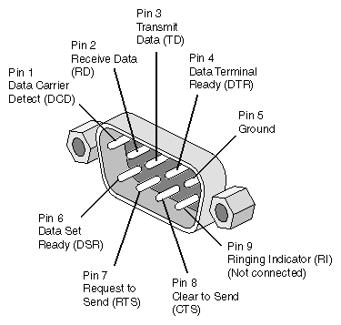
Figure 8 shows the pin assignments for the RJ-45 connector located on the rear panel of the SGI Origin 300 server, SGI Onyx 300 graphics system, and L2 controller.
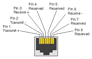
Figure 9 shows the external SCSI VHDCI connector pin locations for the external SCSI connector located on the rear panel of the SGI Origin 300 server and SGI Onyx 300 graphics system. These pin locations are also used for the two SCSI connectors located on the rear panel of the TP900 storage module. Table 4 lists the pin assignments for these SCSI ports.
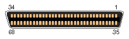
Table 4. SCSI VHDCI Pin Assignments
Pin Number | Signal Name | Pin Number | Signal Name |
|---|---|---|---|
1 | +DB (12) | 35 | -DB (12) |
2 | +DB (13) | 36 | -DB (13) |
3 | +DB (14) | 37 | -DB (14) |
4 | +DB (15) | 38 | -DB (15) |
5 | +DB (P1) | 39 | -DB (P1)) |
6 | +DB (0) | 40 | -DB (0) |
7 | +DB (1) | 41 | -DB (1) |
8 | +DB (2) | 42 | -DB (2) |
9 | +DB (3) | 43 | -DB (3 |
10 | +DB (4) | 44 | -DB (4) |
11 | +DB (5) | 45 | -DB (5) |
12 | +DB (6) | 46 | -DB (6) |
13 | +DB (7) | 47 | -DB (7) |
14 | +DB (P0) | 48 | -DB (P0) |
15 | Ground | 49 | Ground |
16 | DIFFSENS | 50 | Ground |
17 | TERMPWR | 51 | TERMPWR |
18 | TERMPWR | 52 | TERMPWR |
19 | Reserved | 53 | Reserved |
20 | Ground | 54 | Ground |
21 | +ATN | 55 | -ATN |
22 | Ground | 56 | Ground |
23 | +BSY | 57 | –BSY |
24 | +ACK | 58 | –ACK |
25 | +RST | 59 | –RST |
26 | +MSG | 60 | –MSG |
27 | +SEL | 61 | –SEL |
28 | +CD | 62 | –CD |
29 | +REQ | 63 | –REQ |
30 | +IO | 64 | –IO |
31 | +DB (8) | 65 | -DB (8) |
32 | +DB (9) | 66 | -DB (9) |
33 | +DB (10) | 67 | -DB(10) |
34 | +DB (11) | 68 | -DB (11) |
Figure 10 shows the stereo jack connector conductors for the RT interrupt input and RT interrupt output ports on the SGI Origin 300 server and SGI Onyx 300 graphics system. Table 5 lists the conductor assignments for the stereo jack connector.
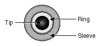
Table 5. Stereo Jack Connector Conductor Assignments
Conductor | Function |
|---|---|
Tip | Interrupt (active low) |
Ring | +5 V |
Sleeve | Chassis ground and cable shield |
Figure 11 shows the USB type A connector pin number locations for the USB port 1 and USB port 2 located on the rear panel of the SGI Origin 300 server and SGI Onyx 300 graphics system. These pin number locations are also used for the four USB ports on the USB hub that connect to the SGI Origin 300 server. Table 6 lists the pin assignments for the USB type A connector pins.
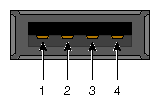
Table 6. USB Type A Connector Pin Assignments
Signal | Color | Pin Number |
|---|---|---|
+Data | Green | 3 |
-data | White | 2 |
VCC | Red | 1 |
Ground | Black | 4 |
Figure 12 shows the USB type B connector pin number locations for the USB L1 port located on the rear panel of the SGI Origin 300 server and SGI Onyx 300 graphics system, for the L1 port on the NUMAlink module, and for the USB type B port connector on the USB hub that connects to the L2 controller. Table 7 lists the pin assignments for the USB type B connector.
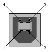
Table 7. USB Type B Connector Pin Assignments
Signal | Color | Pin Number |
|---|---|---|
+Data | Green | 3 |
-data | White | 2 |
VCC | Red | 1 |
Ground | Black | 4 |