The SGI Onyx 300 graphics system offers visualization and supercomputing in one system. This system uses the same NUMA3 architecture as the SGI Onyx 3000 series systems. The SGI Onyx 300 graphics system is a rackmounted system that is composed of separate, but interconnected, functional units called “modules.” Figure 1-1 shows the modules that are available with the graphics system.
 | Note: The NUMAlink, SGI Total Performance (TP900) storage, and PCI expansion modules are optional modules; however, the NUMAlink module cannot be ordered as part of an upgrade. |
This modular design allows you to customize your system to meet your specific graphics requirements. For example, you can choose to have single or multiple InfiniteReality graphics modules to meet your needs.
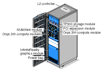
Table 1-1 lists the functional descriptions of the modules that compose the SGI Onyx 300 graphics system.
Module | Description |
|---|---|
InifiniteReality graphics module | Contains one or two graphics pipes. |
Onyx 300 compute module | Provides the compute functionality and base I/O for the system. |
Power bay module | Provides power to the L2 controller, NUMAlink module, and PCI expansion module |
L2 controller module | Provides rack-level control |
NUMAlink module (optional) | Routes information between the Onyx 300 compute modules and the PCI expansion modules |
PCI expansion module (optional) | Provides 12 PCI slots |
TP900 storage module (optional) | Provides additional storage |
The Onyx 300 graphics system has the following features:
Scalable growth of memory and I/O bandwidth as well as processor compute power.
As many as eight InfiniteReality graphics pipes.
As many as eight monitors on each pipe.
High-speed NUMAlink interconnect that links the Onyx 300 compute modules, NUMAlink module, and PCI expansion modules together (a peak rate of 3200 MB/s bidirectionally, 1600 MB/s in each direction).
The Onyx 300 system supports two configurations: a base configuration and a NUMAlink configuration. For both configurations, one Onyx 300 compute module is required for each graphics pipe.
The base configuration is a single-rack system that consists of the following components:
1 or 2 Onyx 300 compute modules (2, 4, 6, or 8 processors)
1 InfiniteReality graphics module with 1 or 2 graphics pipes
1 L2 controller module
1 power bay module that contains 2 power supplies
1 or more TP900 storage modules (optional)
1 PCI expansion module (optional)
Note: This system does not include a NUMAlink module.
A NUMAlink configuration is a single- or multiple-rack system that consists of the following components:
2 to 8 Onyx 300 compute modules (4 to 32 processors)
1 to 8 InfiniteReality modules (1 to 8 graphics pipes)
1 NUMAlink module
1 L2 controller
1 power bay that contains 2 power supplies
1 or more TP900 storage modules (optional)
1 to 4 PCI expansion modules (optional)
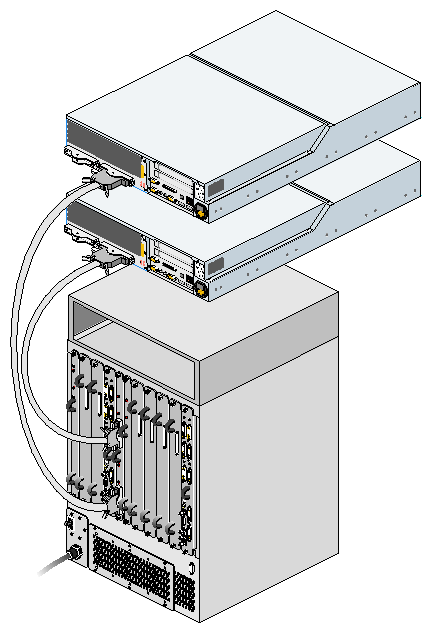
In both configurations, the InfiniteReality graphics module connects to the XIO port of an Onyx 300 compute module as shown in Figure 1-2.
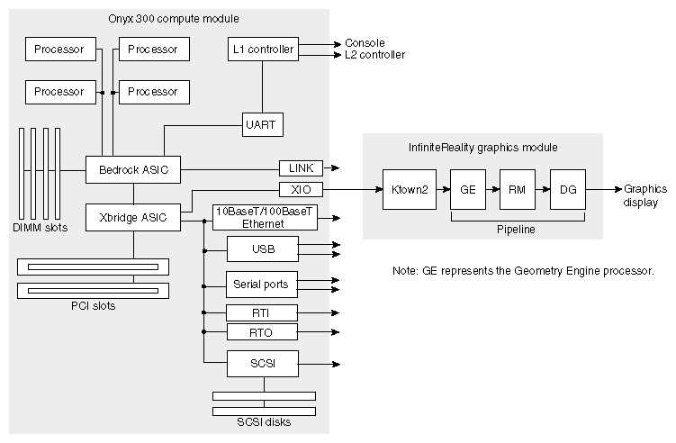
The XIO port of the Onyx 300 compute module connects to the Ktown2 board of the InfiniteReality graphics module as shown in Figure 1-3. In simplified terms, the Ktown2 board converts the data that it receives from the compute module to differential signal levels and passes the signals to the Geometry Engine processor. This processor creates the polygons that are superimposed on the flat image to make it look three dimensional. After it creates the polygons, the Geometry Engine processor passes the polygons to the raster manager (RM). The RM processes the polygons by adding color, texture, and other elements that make the image look real. The RM passes the image to the display generator (DG) for formatting so that the image can be displayed on a monitor.
The following subsections provide detailed descriptions for the standard and optional system components.
| Note: Because the base configuration does not use the NUMAlink module, the NUMAlink module is described as an optional system component. |
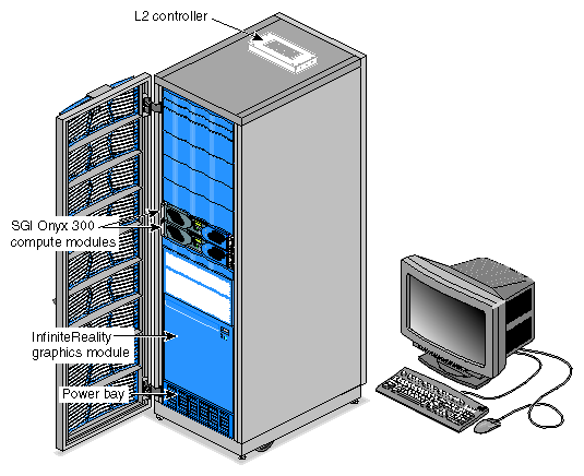
The SGI Onyx 300 system consists of the following standard components, as shown in Figure 1-4.
InfiniteReality graphics module
Onyx 300 compute module
39U rack
L2 controller module
Power bay module
Power distribution unit (PDU) (not shown in Figure 1-4)
Monitor, keyboard, and mouse
USB extender (not shown in Figure 1-4)
Note: The modules of the SGI Onyx 300 graphics system are not interchangeable with the SGI Onyx 3000 series bricks.
The InfiniteReality graphics module is a one- or two-pipe, rackmounted graphics interface that requires 18U of space within a rack. The maximum number of InfiniteReality graphics pipes contained in an Onyx 300 graphics system is eight. Figure 1-5 shows the front and rear views of the graphics module.
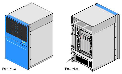
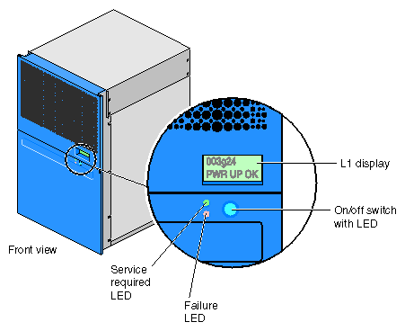
The InfiniteReality graphics module contains the following front-panel items (refer to Figure 1-6):
L1 display is a 2-line by 12-character liquid crystal display (LCD) that displays status and error messages that the L1 controller generates.
On/Off switch with LED enables you to manually power on and power off the module.
-
On/Off switch LED illuminates green when the internal components are powered on.
Service required LED illuminates orange to indicate that an item is not functioning properly, but the InfiniteReality graphics module is still operating.
Failure LED illuminates red to indicate that a failure has occurred and the InfiniteReality graphics module is down.
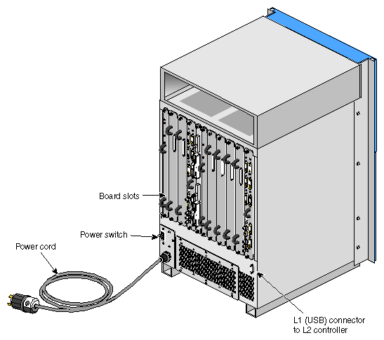
The InfiniteReality graphics module has the following rear-panel items, as shown in Figure 1-7:
Power switch powers on the L1 controller when moved to the On (1) position; moving it to the Off (0) position powers off the L1 controller.
PWR (power) cord attaches to an external 220 Vac power receptacle.
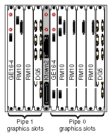
11 board slots that house a Ktown2 board and one or two InfiniteReality graphics pipes. As you face the rear panel, the boards are located as follows:
Six rightmost slots (pipe 0) support a Geometry Engine processor board; one, two, or four raster manager (RM) boards; and a display generator (DG) board.
Four leftmost slots (pipe 1) support a Geometry Engine processor board, one or two RM boards, and a DG board.
Ktown2 board with two connectors is located between pipe 0 and pipe 1. It contains two connectors. The top connector connects pipe 0 (six rightmost slots) to an Onyx 300 compute module. The bottom connector connects pipe 1 (four leftmost slots) to an Onyx 300 compute module.
L1 (USB) connector attaches the InfiniteReality graphics module to the L2 controller.
The InfiniteReality graphics module contains:
The InfiniteReality3 board set consists of the following board types (refer to Figure 1-8):
Ktown2
Geometry Engine (GE16-4)
Raster manager (RM10)
Display generator (DG5)
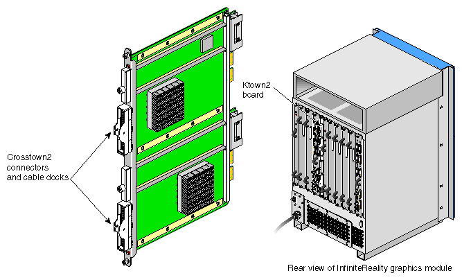
The Ktown2 board, which is physically located between the two pipes, provides two Crosstown2 (Xtown2) connections; the top Xtown2 connector is for the right pipe; the bottom Xtown2 connector is for the left pipe (refer to Figure 1-9). The Xtown2 connectors connect to the XIO port of the Onyx 300 compute modules.
Each graphics module requires one Ktown2 board so that the graphics module can convert the data it receives from the host processors to differential signal levels.
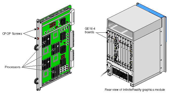
The GE16-4 (Geometry Engine) board contains four processors that process OpenGL commands and vertex data that it receives from the host processors (refer to Figure 1-10). Each pipe contains one GE16-4 board.
The GE16-4 board creates polygons and performs basic geometric transformation, lighting calculations, and other processes that make an image look normal to the human eye. The mathematical processes that take place in the GE16-4 board are measured in polygons per second; the unit for the rate at which data moves through the graphics pipe.
The RM10 (raster manager) boards:
Contain the main memory of the graphics system
Provide the frame buffer
Manage anti-aliasing
Provide appropriate levels of screen resolution
Contain texture memory (TM), which contains textures that can be applied to an image
Each InfiniteReality graphics module supports two graphics pipes: a 2-RM pipe and a 4-RM pipe. The 2-RM pipe, which is physically located to the left of the Ktown2 board, contains one or two RM10 boards. The 4-RM pipe, which is physically located to the right of the Ktown2 board, contains one, two, or four RM10 boards.

The DG5 (display generator) board formats images so that they can be displayed on a monitor or delivered to other devices. The DG5 board:
Converts digital data to analog
Handles all pixel clocking, genlocking, and cursor display functions
Performs the role of functional manager
Connects to the graphics display
The default monitor resolution supported by the InfiniteReality2 and InfniteReality3 board sets and the SuperWide monitor is 1920 x 1200 at 66 MHz. The maximum output bandwidth is approximately 300 Mpix/s. For two monitors, the transfer rate is approximately 188 Mpix/s. If you connect more than two monitors, you must use a combination of low- and high-resolution monitors that are within the limit of 300 Mpix/s.
Each pipe contains one DG5 board (refer to Figure 1-12).
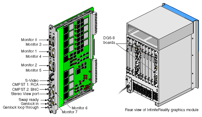
The Onyx 300 graphics system supports six DG5 options (refer to Table 1-2).
Option Name | Description |
|---|---|
DG5-2 | Default DG5 board that is configured with each graphics pipe. It has two high-resolution video outputs that can connect to two monitors. This option does not have a daughtercard. |
DG5-2/DPLEX | DG5-2 board with a digital video multiplexer (DPLEX) daughtercard that enables multiplexing of two or more graphics pipes (referred to as a hyperpipe). The output of the graphics pipes is sent to a single monitor or other video input device. |
DG5-2/GVO | DG5-2 board with a daughtercard that provides real-time graphics-to-video output. |
DG5-2/HDGVO | DG5-2 board with a daughtercard that provides high-definition real-time graphics-to-video output. |
DG5-2/DDO2 | DG5-2 board with a daughtercard that is used for custom hardware-in-the-loop (HITL) simulations. |
DG5-8 | DG5 board that has eight high-resolution video outputs that can connect to eight monitors. This option has a VIO5H daughtercard. |
The DG5 options have the standard connections that are listed in Table 1-3.
Table 1-3. DG5 Standard Connections
Label | Type | Function |
|---|---|---|
Monitors 0 through X | 13W3 | Variable high-resolution monitor outputs |
S-Video | 4-pin mini-DIN | Interface to SVHS VCR or monitor |
CMPST 1 | RCA jack | Interface to composite monitor or VCR |
CMPST 2 | BNC | Interface to composite monitor or VCR |
Stereo View | 9-pin sub-D | Interface to Stereo View goggles |
Swap-ready | BNC | Interface to other graphics pipes |
Genlock in | BNC | Interface to house sync or other pipes |
Genlock loop-through | BNC | Loop-through connection |
The L1 controller performs various functions for the InfiniteReality graphics module; for example, the L1 controller monitors the voltage and temperature of the module. The L1 controller display, which is located on the front of the graphics module, (refer to Figure 1-13) is a liquid crystal display (LCD) that displays error and status messages that the L1 controller generates.
The L1 controller also has the following switch and LEDs:
On/Off switch with LED enables you to manually power on and power off the module. The LED illuminates green when the internal components are powered on.
Service required LED illuminates orange to indicate that an item is not functioning properly, but the InfiniteReality graphics module is still operating.
Failure LED illuminates red to indicate that a failure has occurred and the InfiniteReality graphics module is down.
The midplane provides connections for the board set, power supply, and L1 controller (refer to Figure 1-14).
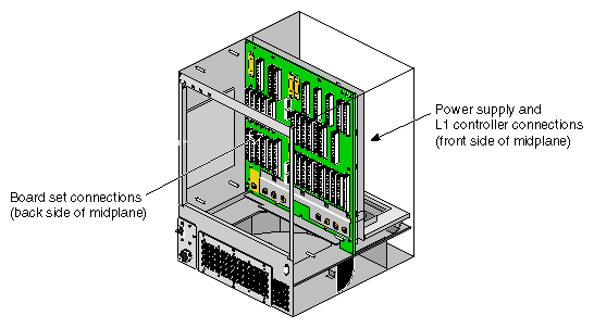
The InfiniteReality graphics module has its own power supply, which requires an external 220 Vac power receptacle. The power supply is located on the front side of the midplane (refer again to Figure 1-14).
The Onyx 300 compute modules provide the compute functionality for the system. The base configuration of the SGI Onyx 300 system consists of one or two Onyx 300 compute modules. The NUMAlink configuration consists of two to eight Onyx 300 compute modules. The number of required compute modules depends on the number of graphics pipes in the system. Each graphics pipe is paired with a compute module.
Each compute module consists of:
Two or four 64-bit MIPS RISC processors
2 MB of secondary cache per processor
512 MB to 4 GB of memory
One or two sled-mounted Ultra3 SCSI disk drives
Zero to two PCI cards
Note: A compute module is not limited to two disk drives or two PCI slots. The compute module can connect to external devices that expand the I/O and storage capabilities. Information about these devices is provided in “Optional System Components”.
Each compute module also contains an L1 controller that provides the following services:
Controls and sequences power
Controls and monitors the environment
Initiates a reset
Stores identification and configuration information
These compute modules communicate with each other via the NUMAlink 3 interconnect. They communicate with the graphics modules via their XIO ports.
Figure 1-15 shows the front and rear views of an SGI Onyx 300 compute module.
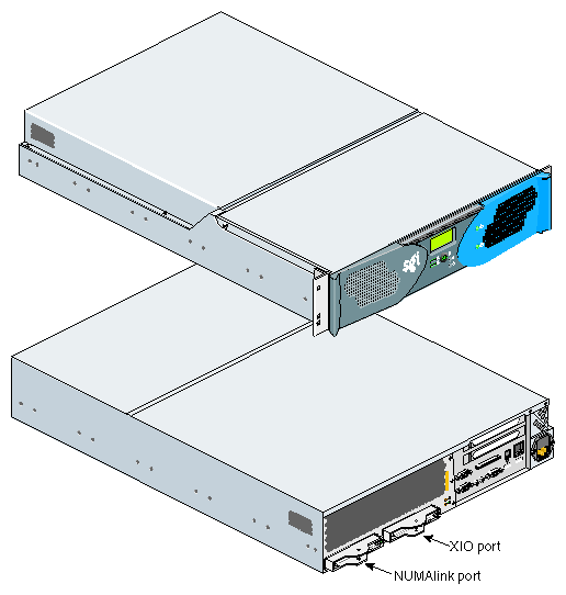
Figure 1-16 illustrates the front controls and indicators of the SGI Onyx 300 compute module.
L1 controller display is a liquid crystal display (LCD) that displays status and error messages that the L1 controller generates.
On/Off switch with LED enables you to manually power on and power off the Onyx 300 compute module. Alternatively, you can power on and off the compute module at a system console. The LED illuminates green when the internal components are on.
Reset button resets the internal processors, ASICs, and memory.
Note: This reset causes memory loss. (Refer to the non-maskable interrupt [NMI] to perform a reset without losing memory.) Non-maskable interrupt (NMI) button resets the internal processors and ASICs without losing memory. Register data and memory are stored in a /var/adm/crash file.
Service required LED illuminates yellow to indicate that an item has failed or is not operating properly, but the system is still operating.
Failure LED illuminates red to indicate that a failure has occurred and the compute module is down.
Drive LEDs illuminate green to indicate drive activity.
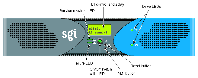
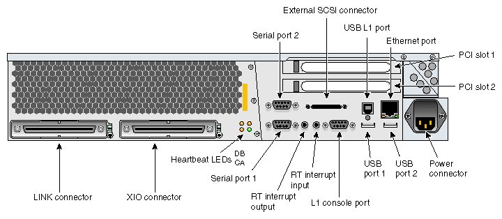
Figure 1-17 illustrates the rear panel I/O ports and features of the SGI Onyx 300 compute module.
Power connector attaches to a power cord that connects the module to an AC power outlet.
LINK connector (NUMAlink connector) connects the compute module to another compute module, a NUMAlink module, or a PCI expansion module. This connection is made with a NUMAlink 3 cable at 1.6 GB/s in each direction.
XIO connector connects to the InfiniteReality graphics module.
L1 console port (DB-9, RS-232, console and diagnostic port) connects the compute module's L1 controller to a system console that contains SGIconsole software.
USB L1 port (universal serial bus) connects the compute module's L1 controller to the L2 controller.
PCI slots 1 and 2 house PCI cards. The two PCI 2.2-compliant slots are configured on one bus. The PCI bus supports both 32- and 64-bit modes at 33 or 66 MHz. Refer to the SGI Supportfolio Online home page at http://support.sgi.com for an updated list of supported PCI cards.
Serial ports 1 and 2 (DB-9, RS-232, or RS-422 connectors) can be used as COM ports to connect modems or other serial devices.
USB ports 1 and 2 connect auxiliary equipment such as a keyboard or a mouse.
RT interrupt input and output (real-time interrupts) are used by the graphics cards to keep the graphics synchronized.
Ethernet port (autonegotiating 10BaseT or 100BaseT Ethernet port) connects the compute module to an Ethernet network.
External SCSI connector (68-pin VHDCI external SCSI port) connects to SCSI devices (for example, TP900 storage module). Refer to the SGI Supportfolio Online home page at http://support.sgi.com for an updated list of supported SCSI devices.
Heartbeat LEDs (four, one for each processor) indicate processor activity.
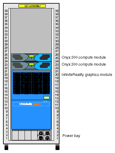
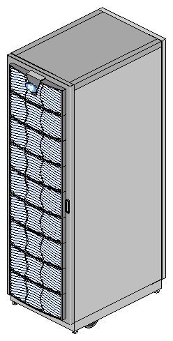
The modules that compose the SGI Onyx 300 system reside in one or more 39U racks.
The components within the rack are identified by the lowest unit number that they occupy. For example, the top Onyx 300 compute module shown in Figure 1-18 is identified as U24.
The 39U rack has the following characteristics:
19-in. mounting rails to support the components within the rack
Front and rear doors
Cable management hardware in the rear of the rack
Mounted on four castors, two of which are swivel castors
Seismic tie-down attachment points
Leveling pads
Figure 1-19 shows the front view of the 39U rack.
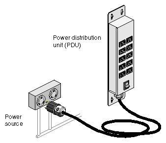
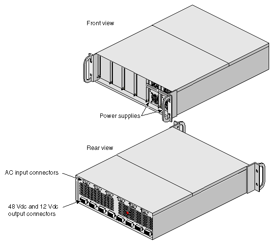
The power components of the SGI Onyx 300 graphics system consist of one or two power distribution units (PDUs) (refer to Figure 1-20) and one power bay module (refer to Figure 1-21). The number of PDUs depends on the number of modules within the rack. The PDU inputs AC voltage from an external power receptacle and outputs AC voltage to the Onyx 300 compute modules, the power bay module, the local USB extender, optional TP900 storage modules, and optional USB hub.
The power bay module converts the AC voltage to 48 Vdc and 12 Vdc standby voltage and outputs this voltage to the optional NUMAlink module, the L2 controller, and optional PCI expansion modules. The 48 Vdc powers on the NUMAlink module, the PCI expansion modules, and the L2 controller. The 12 Vdc standby voltage powers on the L1 controller logic within the NUMAlink module and the PCI expansion modules.
The power bay module can house up to six power supplies; however, the Onyx 300 graphics system requires only two power supplies. Each power supply inputs single-phase AC power and outputs a maximum of 950 W at 48 Vdc and 42 W at 12 Vdc standby.
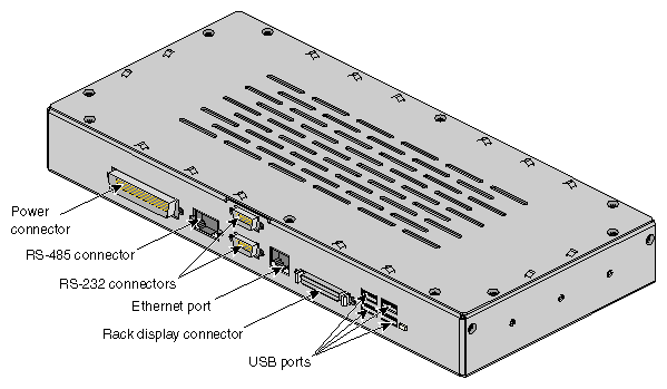
The L2 controller module, shown in Figure 1-22, is a rack-level controller that performs the following functions:
Controls resource sharing
Controls L1 controllers
Maintains controller configuration and topology information
Enables remote maintenance
Routes data between upstream and downstream devices, as follows:
Upstream devices (for example, the system console) provide control for the system, initiate commands for the downstream devices, and act on the messages that they receive from downstream devices.
Downstream devices (for example, L1 controllers) perform the actions specified by the L2 controller commands, send responses to the L2 controller that indicate the status of the commands, and send error messages to the L2 controller.
The L2 controller has the following connectors (refer to Figure 1-22):
Power connector that connects the L2 controller to the power bay module
Two RS-232 ports (DB-9) that connect the L2 controller to a modem
10BaseT Ethernet port that connects the L2 controller to an Ethernet hub (system console that contains SGIconsole software)
Four USB ports ; these ports can connect the L2 controller to the following components:
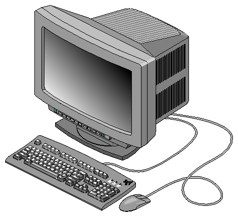
Every SGI Onyx 300 graphics system is configured with one 24-inch SuperWide graphics monitor, a standard USB 101-key international keyboard, and a three-button USB mouse. Refer to Figure 1-23.
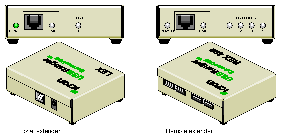
The USB extender enables you to place the keyboard and mouse up to 100 meters (328 ft) from the Onyx 300 compute module. The standard configuration provides a 30-ft cable. The USB extender consists of two components: a local extender (LEX) and a remote extender (REX). The LEX receives AC power from the PDU in the rack. The REX does not use an external power source.
The Onyx 300 graphics system can contain the following optional components, which are discussed in the subsections that follow.
NUMAlink module
PCI expansion modules
Storage expansion modules
Tape devices
USB hub
CD-ROM
Genelec bi-amplified speakers
Radical audio PCI card
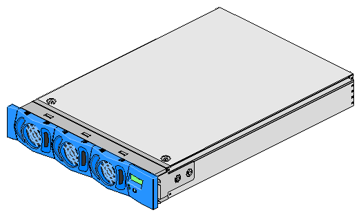
The NUMAlink module, shown in Figure 1-25, is an air-cooled device that transfers messages between the Onyx 300 compute modules via the NUMAlink 3 interconnect. This module is required for graphics systems that contain more than two graphics pipes.
The NUMAlink module consists of eight ports; four ports can connect to four Onyx 300 compute modules. The other four ports, which carry USB signals, can connect to Onyx 300 compute modules or PCI expansion modules.
| Note: The USB signals enable the Onyx 300 compute modules and the PCI expansion modules to communicate with the L2 controller. The Onyx 300 compute modules that connect to the four ports that do not carry USB signals communicate with the L2 controller via a USB hub. |
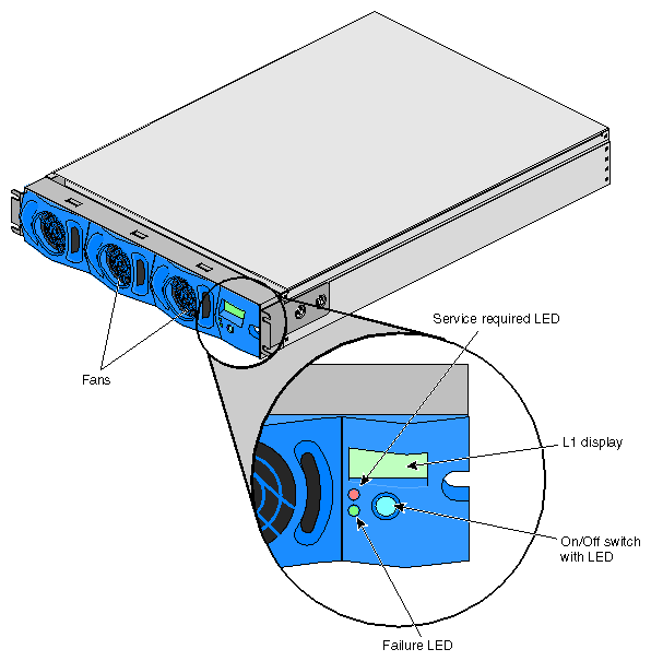
The NUMAlink module contains the following front-panel items (refer to Figure 1-26):
L1 display is a 2-line by 12-character liquid crystal display (LCD) that displays status and error messages that the L1 controller generates.
On/Off switch with LED enables you to manually power on and power off the module.
-
On/Off switch LED illuminates green when the internal components are powered on.
Service required LED illuminates orange to indicate that an item is not functioning properly (for example, a fan is off), but the NUMAlink module is still operating.
Failure LED illuminates red to indicate that a failure has occurred and the NUMAlink module is down.
Fans that provide N+1 redundant cooling for the module.
Note: The front of the NUMAlink module appears to display three cooling fans; however, only the middle and right fans are present.
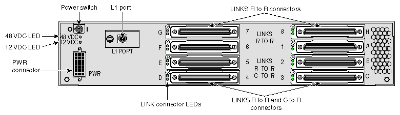
The NUMAlink module has the following rear panel items (refer to Figure 1-27):
Power switch powers on the L1 controller when moved to the 1 position; moving it to the 0 position powers off the L1 controller.
12 VDC LED illuminates green when the power switch is in the On position and the power bay supplies 12 Vdc to the module.
48 VDC LED illuminates green when the power bay supplies 48 Vdc to the module at the request of the L1 controller.
PWR (power) connector attaches to the power bay module via a DC power cable.
L1 port connector connects the NUMAlink module to the L2 controller. The USB hub receives the USB signals from the L2 controller via this port and distributes these USB signals to the L1 controllers of the Onyx 300 compute modules and PCI expansion modules that are attached to ports 2, 3, 4, and 5.
LINKS R TO R connectors (also referred to as ports 1, 6, 7, and 8 or A, F, G, and H) connect Onyx 300 compute modules to the NUMAlink module.
LINKS R TO R and C TO R connectors (also referred to as ports 2, 3, 4, and 5 or B, C, D, and E) connect Onyx 300 compute modules and/or PCI expansion modules to the NUMAlink module.
Besides NUMAlink signals, ports 2, 3, 4, and 5 transfer USB signals between the USB hub of the NUMAlink module and the L2 controller.
LINK connector LEDs. Each NUMAlink connector has two LEDs:
The green LED illuminates to indicate that a cable is connected properly between the NUMAlink module and another module.
The yellow LED illuminates to indicate that the L1 controller detected the “Remote Power OK” signal from the module on the other end of the cable.
Each Onyx 300 compute module contains two PCI slots; however, you can expand your I/O capabilities by adding one to four PCI expansion modules to your system. The following rules indicate how many PCI expansion modules you can add to your system:
You can add one PCI expansion module to a system that contains two to seven compute modules.
You can add two PCI expansion modules to a system that contains two to six compute modules.
You can add three PCI expansion modules to a system that contains three to five compute modules.
You can add four PCI expansion modules to a system that contains four compute modules.
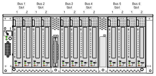
The PCI expansion module, shown in Figure 1-28, contains six buses (buses 1 through 6) that can seat as many as twelve 3.3-V or universal PCI cards. Each bus has two PCI slots (refer to Figure 1-29) that are labeled 1 and 2 and that support either two 33-MHz PCI cards or two 66-MHz PCI cards.
The PCI expansion module connects to an Onyx 300 compute module via the LINK (NI) port or a NUMAlink module.
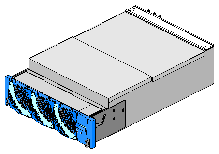
Figure 1-29 shows the PCI card slot numbering on the PCI expansion module.
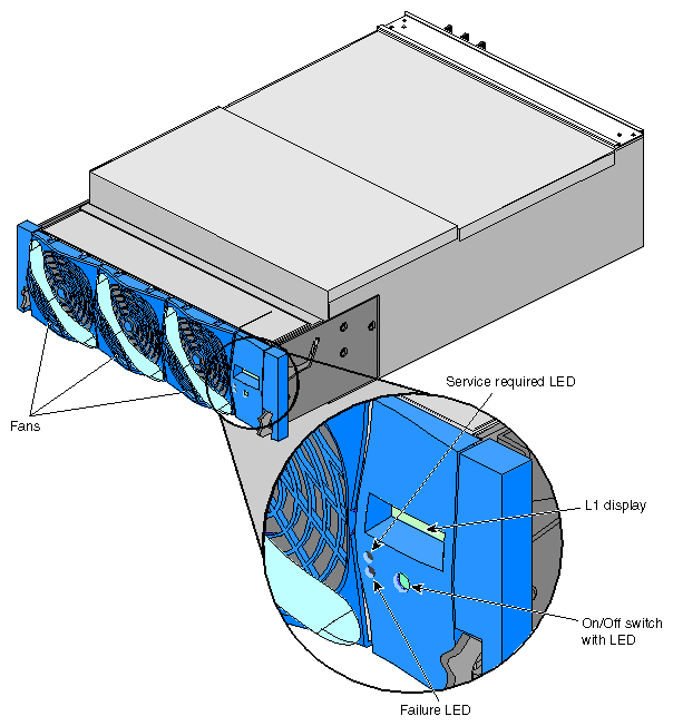
The PCI expansion module contains the following front-panel items (refer to Figure 1-30):
L1 display is a 2-line by 12-character liquid crystal display (LCD) that displays status and error messages that the L1 controller generates.
On/Off switch with LED enables you to manually power on and power off the module.
-
On/Off switch LED illuminates green when the internal components are powered on.
Service required LED illuminates orange to indicate that an item is not functioning properly (for example, a fan is off), but the PCI expansion module is still operating.
Failure LED illuminates red to indicate that a failure has occurred and the PCI expansion module is down.
Three fans that provide N+1 redundant cooling for the module.
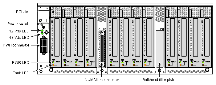
The PCI expansion module has the following rear-panel items (refer to Figure 1-31):
Power switch powers on the L1 controller when moved to the 1 position; moving it to the 0 position powers off the L1 controller.
12 Vdc LED illuminates green when the power switch is in the On position and the power bay supplies 12 Vdc to the module.
48 Vdc LED illuminates green when the power bay supplies 48 Vdc to the module at the request of the L1 controller.
PWR (power) connector attaches to the power bay via a DC power cable.
PCI slots seat the PCI cards. Each slot has two LEDs:
PWR (power) LED illuminates green when the PCI card carrier is installed securely and is receiving power.
Fault LED illuminates orange when a fault occurs with the PCI card.
NUMAlink connector attaches the PCI expansion module to a NUMAlink module or an Onyx 300 compute module via a NUMAlink cable.
Bulkhead filler plate covers the unused connector slot so that air flows properly through the module.
Each Onyx 300 compute module contains two disk-drive bays; however, you can add additional storage to the system as follows:
For a SCSI (small computer system interface) JBOD (just a bunch of disks) solution, SGI offers the SGI Total Performance 900 (TP900) storage module.
For a Fibre Channel solution that supports both JBOD and RAID configurations, SGI offers the SGI Total Performance 9100 (TP9100) storage system.
For a Fibre Channel RAID solution, SGI offers the SGI Total Performance 9400 (TP9400) storage system.
These solutions are discussed in the subsections that follow.
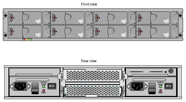
The SGI TP900 storage module, shown in Figure 1-32, is a 2U-high 8-drive storage system that provides compact, high-capacity, high-availability JBOD storage for supported SGI compute modules. The enclosure backplane connects the 8 drives on one SCSI bus. As an option, the storage module can also be configured on two SCSI buses (two strings of four drives).
This storage module has the following features:
Low cost
Mounts in a standard 19-in. rack; available in factory-installed configurations
Uses SCSI Parallel Interface 3 (SPI-3) capable Low Profile (1-inch high) 3.5-inch disk drives
Drive carriers that accept SGI-qualified 10,000 or 15,000 RPM U160 SCSI disk drives
The front of the SGI TP900 chassis consists of eight drive bays that contain either disk drive carrier modules or dummy carrier modules. The front of the TP900 is four bays wide by two bays high. The drive bays are numbered 1 and 2 from top to bottom and 1 to 4 from left to right. Refer to Figure 1-33.
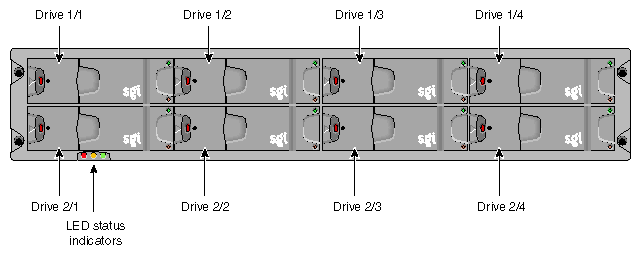
The front of the chassis also contains three LED status indicators. Table 1-4 provides more information about these LEDs.
LED | Status |
|---|---|
System status | Green signifies that power is applied to the enclosure. |
Power status | Green signifies that the power supplies are functioning normally. |
Cooling status | Green signifies that all fans are functioning normally. |
The rear of the TP900 storage module contains six bays that house power supply, cooling, and SCSI I/O modules. Refer to Figure 1-34. The rear of the TP900 storage module is three bays wide by two bays high. The bays are numbered 1 and 2 from top to bottom and 1 to 3 from right to left.
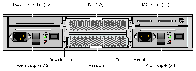
The TP900 rear bays house the following components:
1 or 2 power supply modules (The second power supply is optional.)
Power supply voltage operating ranges are nominally 115 V or 230 V and are selected automatically. The power supply module contains two LEDs that are located on the front panel of the power supply. The green LED indicates power output. The amber LED indicates a power supply failure.
1 or 2 input/output (I/O) modules
Each I/O module contains two VHDCI connectors and a switch to set the SCSI ID range. When only one I/O module is present in the system, the other I/O module location contains a loopback module that has no external connectors.
1 or 2 cooling modules (The second cooling module is optional.)
The cooling module consists of fans that cool the components of the storage module. In addition, the cooling module has two LEDs that are located on the front panel of the cooling module. The green LED indicates that the cooling module is functioning properly. The amber LED indicates a fan failure.
Blank modules
Blank modules are placed in all vacant power supply and cooling module bays to maintain proper airflow through the system.
The SGI Total Performance 9100 (TP9100), shown in Figure 1-35, is an affordable, entry-level RAID storage array that is easily expandable and comes in either a deskside tower or a rackmounted configuration. You can start with a basic JBOD configuration and later add RAID controllers or you can start with a RAID configuration. By purchasing a deskside model, you can start small and scale to a multi-terabyte environment. The drives within the deskside tower can easily slide into a rack to increase storage capacity. The compact design of the TP9100 enables as many as 108 drives to fit in a single cabinet.
This storage system has the following features:
Converts easily from JBOD to RAID.
Supports RAID levels 0, 1, 1+0, 3, and 5.
The base unit comes with one RAID controller and can be upgraded to two controllers, allowing no single point of failure.
Supports the latest in high-performance 18-GB, 36-GB, or 73-GB 10,000 RPM FC-AL (fibre channel-arbitrated loop) drives.
Can be configured with as many as 60 drives per controller.
Support for multi-platform OS-based servers: IRIX, Linux, Microsoft Windows NT, and Microsoft Windows 2000.
Fully tested in SAN and switch environments.
Nine TP9100 arrays can be rackmounted into a single cabinet, for a maximum of 108 drives per cabinet.
Uninterrupted data access with automatic failover capability and hot-swappable, redundant components.
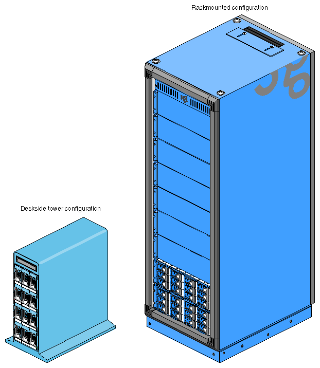
The SGI Total Performance 9400 (TP9400), shown in Figure 1-36, is a highly scalable RAID storage subsystem. It supports more than 8 TB of fast storage in a 19-inch rack enclosure and can grow from as few as 73 GB of storage to whatever size you require without disruption to normal processing activities. The TP9400 has continuous availability; all active components may be configured redundantly and installed “hot” as customer replaceable or expansion units.
This storage system has the following features:
Full RAID support, implemented in hardware with custom ASICs for performance.
Total fibre channel design, including all-fibre dual-ported disk drives.
As many as eight internal optical fibre hubs for online expansion and connectivity.
Four fibre channel loops support I/O reads as fast as 357 MB/s and writes as fast as 239 MB/s.
Direct attachment of up to eight host systems using optical fibre cables.
Full support for all SAN topologies.
Dual active controllers with as much as 1 GB redundant cache and dual battery backup.
User-friendly GUI or command line interface software for installation and management.
In-band and out-of-band management, including e-mail event notification.
As many as 100 drives in each rack (36- or 73-GB 10,000-RPM drives).
Support for system and file clustering.
Host failover software supports logical volume management and load balancing.
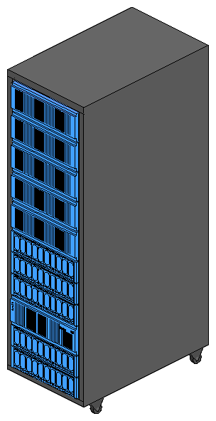
The Onyx 300 graphics system supports the following DAT (digital audio tape) option:
All of the following tape devices have faster transfer rates, can store larger amounts of data, and, in general terms, are more reliable and more scalable than the DAT option. The main differences between these devices is the mode of operation; they are either start/stop devices or streaming devices. Start/stop devices are better suited for HSM (hierarchical storage management) applications where access to the first byte of data is critical and heavy start- and stop-activity takes place. Streaming devices are better suited for backup and restore applications where massive amounts of data are being written and read in one operation.
The start/stop devices are:
9840. Offers SCSI and native fibre channel connectivity, storage capacity of 20 GB (native), and a data transfer rate of 10 MB/s.
9840B. Offers SCSI and native fibre channel connectivity, storage capacity of 20 GB (native), and a data transfer rate of 20 MB/s.
9940. Offers SCSI and native fibre channel connectivity, storage capacity of 60 GB (native), and a data transfer rate of 10 MB/s.
The streaming devices are:
DLT (digital linear tape) 8000 (7000 emulation). Offers SCSI connectivity, storage capacity of 35 GB, and a data transfer rate of 5.0 MB/s.
DLT 8000 (native mode). Offers SCSI connectivity, storage capacity of 40 GB, and a data transfer rate of 6.0 MB/s.
ULTRIUM LTO. Offers SCSI connectivity, storage capacity of 100 GB (native), and a data transfer rate of 15 MB/s.
SDLT. Offers SCSI connectivity, storage capacity of 110 GB, and a data transfer rate of 11 MB/s. The SDLT is backward read compatible (BRC) with DLT 4000, DLT 7000, and DLT 8000 drives; however, SDLT performance is affected when reading legacy media.
The 4mm DAT can be mounted in the Onyx 300 rack or placed on a table. All other supported tape devices are housed within one of the following libraries: L20, L40, L80, L180, or L700 (refer to Table 1-5).
| Note: In Table 1-5, device transfer rates are dictated by the profile of the data being transferred and are likely to be less than the rated speed, depending on the size of files and the block size. |
Table 1-5. Tape Drive Libraries
Library | Specifications |
|---|---|
Number of cartridge slots: 10 or 20 Number of drives: 1 or 2 Supported drives: DLT 8000 (native mode), LTO ULTRIUM, and SDLT Cartridge capacity: DLT 8000: 800 GB (20 slots, UNC) - 1.6 TB (20 slots, COM) LTO ULTRIUM: 2.0 TB (20 slots, UNC) - 4.0 TB (20 slots, COM) SDLT: 2.2 TB (20 slots, UNC) - 4.4 TB (20 slots, COM) Drive data rate: DLT 8000: 43.2 GB/hr (2 drives, UNC) - 86.4 GB/hr (2 drives, COM) LTO ULTRIUM: 108 GB/hr (2 drives, UNC) - 216 GB/hr (2 drives, COM) SDLT: 79.2 GB/hr (2 drives, UNC) - 158.4 GB/hr (2 drives, COM) | |
Number of cartridge slots: 20 or 40 Number of drives: 1 to 4 Supported drives: DLT 8000 (native mode), LTO ULTRIUM, and SDLT Cartridge capacity: DLT 8000: 1.6 TB (40 slots, UNC) - 3.2 TB (40 slots, COM) LTO ULTRIUM: 4.0 TB (40 slots, UNC) - 8.0 TB (40 slots, COM) SDLT: 4.4 TB (40 slots, UNC) - 8.8 TB (40 slots, COM) Drive data rate: DLT 8000: 86.4 GB/hr (4 drives, UNC) - 172.8 GB/hr (4 drives, COM) LTO ULTRIUM: 216 GB/hr (4 drives, UNC) - 432 GB/hr (4 drives, COM) SDLT: 158.4 GB/hr (4 drives, UNC) - 316.8 GB/hr (4 drives, COM)
Key: UNC = uncompressed, COM = compressed | |
Number of cartridge slots: 40, 60, or 80 Number of drives: 1 to 8 Supported drives: DLT 8000 (native mode), LTO ULTRIUM, and SDLT Cartridge capacity: DLT 8000: 3.2 TB (80 slots, UNC) - 6.4 TB (80 slots, COM) LTO ULTRIUM: 8.0 TB (80 slots, UNC) - 16.0 TB (80 slots, COM) SDLT: 8.8 TB (80 slots, UNC) - 17.6 TB (80 slots, COM) Drive data rate: DLT 8000: 172.8 GB/hr (8 drives, UNC) - 345.6 GB/hr (8 drives, COM) LTO ULTRIUM: 432 GB/hr (8 drives, UNC) - 864 GB/hr (8 drives, COM) SDLT: 316.8 GB/hr (8 drives, UNC) - 633.6 GB/hr (8 drives, COM)
| |
Number of cartridge slots: 84, 140, or 174 Number of drives: 1 to 10 Supported drives: DLT 8000 (native mode), DLT 8000 (7000 emulation), LTO ULTRIUM, and SDLT or Number of drives: 1 to 6 Supported drives: 9840 and 9840B Cartridge capacity: DLT 8000 (native): 6.96 TB (174 slots, UNC) - 13.92 TB (174 slots, COM) DLT 8000 (7000 em): 6.09 TB (174 slots, UNC) - 12.18 TB (174 slots, COM) LTO ULTRIUM: 17.4 TB (174 slots, UNC) - 34.8 TB (174 slots, COM) SDLT:- 19.14 TB (174 slots, UNC) - 38.28 TB (174 slots, COM) 9840: 3.48 TB (174 slots, UNC) - 6.96 TB (174 slots, COM) Drive data rate: DLT 8000 (native): 216 GB/hr (10 drives, UNC) - 432 GB/hr (10 drives, COM) DLT 8000 (7000 em): 180 GB/hr (10 drives, UNC) - 360 GB/hr (10 drives, COM) LTO ULTRIUM: 540 GB/hr (10 drives, UNC) - 1.08 TB/hr (10 drives, COM) SDLT: 396 GB/hr (10 drives, UNC) - 792 GB/hr (10 drives, COM) 9840: 216 GB/hr (6 drives, UNC) - 432 GB/hr (6 drives, COM) 9840b: 432 GB/hr (6 drives, UNC) - 864 GB/hr (6 drives, COM) |
Table 1-6 lists the supported tape options and their specifications.
Table 1-6. Tape Drive Comparison Chart
Tape Device | Interface | Media Capacity | Transfer Rate | Mount Location |
|---|---|---|---|---|
4mm DAT | SCSI | 20 GB | 2.36 MB/s | Onyx 300 rack or table |
9840 | SCSI and | 20 GB | 10 MB/s | L180 or L700 |
9840B | SCSI and | 20 GB | 20 MB/s | L180 or L700 |
DLT 8000 | SCSI | 35 GB | 5 MB/s | L180 or L700 |
DLT 8000 (native mode) | SCSI | 40 GB | 6 MB/s | All libraries |
9940 | SCSI and | 60 GB | 10 MB/s | L700 |
LTO ULTRIUM | SCSI | 100 GB | 15 MB/s | All libraries |
SDLT | SCSI | 110 GB | 11 MB/s | All libraries |
The USB hub, shown in Figure 1-37, routes information between the L2 controller and the four Onyx 300 compute modules that connect to NUMAlink module ports 1, 6, 7, and 8 (the ports that do not carry USB signals). In multiple-rack systems, USB hubs also route information between the L2 controller and the InfiniteReality graphics modules.
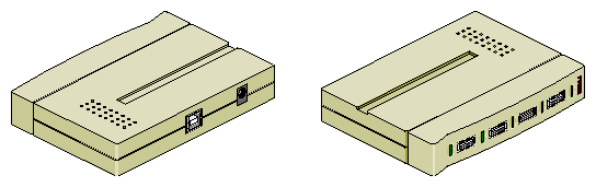
The 40X CD-ROM drive is a half-height, high-capacity (approximately 600 MB, formatted), high-performance device that is packaged in a custom external enclosure designed to match other SGI external peripherals. It is capable of transferring data at up to 6.0 MB/s. It can connect to the Onyx 300 compute module via the SCSI port connector or a SCSI PCI card.
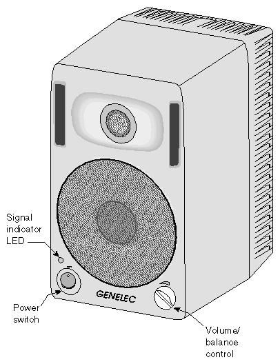
An SGI Onyx 300 graphics system can connect to Genelec digital audio speakers that have the following features:
Radical audio PCI card provides Audio Engineering Society (AES) digital audio input and output. It has eight input/output channels and a BNC AES connector.
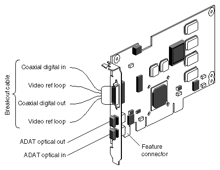
Table 1-7 describes the connectors.
Table 1-7. Audio PCI Card Connectors
Connector | Description |
|---|---|
Coaxial digital audio input | AES-3id 75-ohm BNC connector, breakout cable AES11 synchronization input (for audio clock rates) AES3 professional 2-channel 24-bit digital Compatible with IEC958, S/PDIF consumer 2-channel digital |
Video reference loop | 75-ohm BNC connector, breakout cable |
Coaxial digital audio output | AES-3id 75-ohm BNC connector, breakout cable AES11 synchronization output AES3 professional 2-channel 24-bit digital Compatible with IEC958, S/PDIF consumer 2-channel digital |
ADAT optical in | 12.8-Mb/s SHARP multimode plastic fiber-optic connector, PCI I/O panel 8-channel, 24-bit ADAT optical interface Compatible with IEC958, S/PDIF consumer 2-channel digital |
ADAT optical out | 12.8-Mb/s SHARP multimode plastic fiber-optic connector, PCI I/O panel 8-channel, 24-bit ADAT optical interface Compatible with IEC958, S/PDIF consumer 2-channel digital |