This chapter describes how to remove Dual Head graphics from a Silicon Graphics Octane2, and reinstall the original single head graphics.
Before removing the Dual Head graphics option, you must power off the Octane2 workstation, wait 5 minutes for the heat sinks to cool, and attach a wrist strap. If you have not already done so, see “Preparing the Workstation to Install the Dual Head XIO Module” in Chapter 1 and follow the instructions through attaching the wrist strap. Be sure to also read “Guidelines for Storing and Handling Compression Connectors” in Appendix B before beginning your task. Then return here for instructions on removing the Dual Head graphics option.
 | Caution: Do not touch the gold (front) surface of the XIO compression connector. Touching it could damage the connector. Place a protective cap on the XIO compression connector to prevent damage when the XIO boards are removed from the Octane2 workstation. See Appendix B, “Care and Cleaning of Compression Connectors”. |
The instructions in this section assume that you have completed the instructions in “Preparing the Workstation to Install the Dual Head XIO Module” in Chapter 1, and now have an Octane2 that:
Is powered off and unplugged
Has been sitting for 5 minutes to allow the heatsinks to cool
Has a wrist strap properly attached
If you have not already done so, go to “Preparing the Workstation to Install the Dual Head XIO Module” in Chapter 1 and follow the instructions through attaching the wrist strap. Then return here and follow the directions.
| Caution: When you remove the Dual Head XIO Module, the compression connectors on the back of the XIO boards are accessible and easily damaged. Do not touch or bump the bristled pad (shown in Figure 5-1). All XIO graphics boards have compression connectors, as do most XIO option boards. Before you remove the Dual Head XIO Module, read Appendix B, “Care and Cleaning of Compression Connectors”. |

 | Warning: The heat sinks on the XIO boards become very hot. Wait 5 minutes after powering off the Octane2 workstation before you remove the Dual Head XIO module. Test before touching any of the XIO boards. |
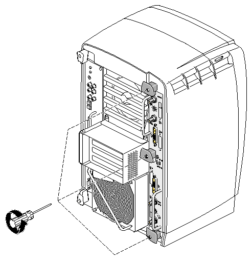
Using the supplied Phillips screwdriver, loosen the three captive screws in the Dual Head XIO module plastic knobs, as shown in Figure 5-2, until the screws are disconnected from the chassis.
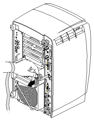
Grasp the center plastic knob and pull until the Dual Head XIO module latch protrudes about an inch (2.5 cm) from the chassis, as shown in Figure 5-3.
The knob moves out about one inch (2.5 cm) before the I/O panel moves.
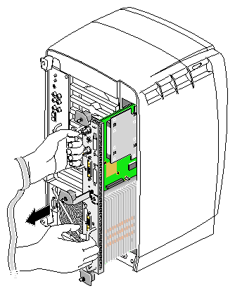
Grasp the handles on the Dual Head XIO module and slide the module out of the chassis, as shown in Figure 5-4. You may also wish to support the bottom of the module while sliding it out.
The center plastic knob protrudes when the Dual Head XIO module is out of the chassis.

Note: Do not push on the knob after you have removed the Dual Head XIO module from the chassis. The module locks to the workstation only if the knob is protruding. Place the Dual Head XIO module on a flat, antistatic surface. An empty antistatic bag on your desk works well.
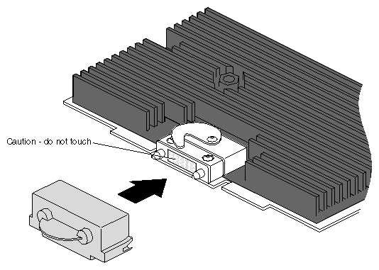
Caution: Do not touch or bump the gold (front) surface of the XIO compression connectors. Touching them could damage the connectors. Place a protective cap on the XIO compression connectors to prevent damage when the XIO boards are removed from the Octane2 workstation. See Appendix B, “Care and Cleaning of Compression Connectors”. Place a cap over each XIO board compression connector. Spare caps are shipped with the Octane2 workstation. See Figure 5-5.
Follow the instructions in this section to reinstall an XIO Tri-Module in an Octane2 workstation.
The instructions in this section assume that you have completed the instructions in “Removing the Dual Head XIO Module”, and now have an Octane2 that:
Is powered off and unplugged
Has an empty XIO module slot
Has a wrist strap properly attached
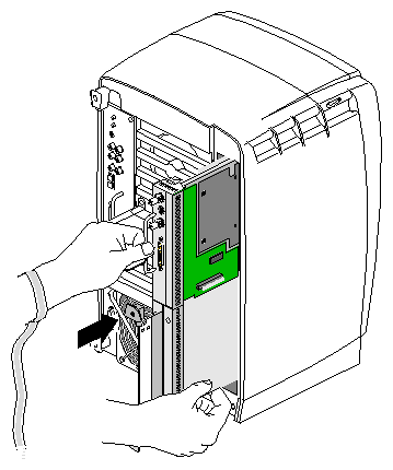
Remove the caps from all compression connectors on the XIO Tri-Module.
Slide the XIO Tri-Module into the guides on the top and bottom of the workstation, as shown in Figure 5-6. Be sure the module is oriented correctly, as shown. There may or may not be other XIO boards in slots C and D (the bottom two slots) but the graphics board set should always be in slots A and B (the top two slots).
Before you insert the XIO Tri-Module, make sure the plastic knob assembly protrudes in a locked position from the I/O panel, as shown in Figure 5-6.
If the plastic knobs are flush with the I/O panel, the XIO Tri-Module will stop during insertion. If this happens, back the entire assembly out of the slot about one inch (2.5 cm), pull out the plastic knobs, and then continue inserting the XIO Tri-Module into the chassis.
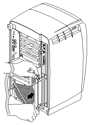
Make sure that the XIO Tri-Module has been inserted fully into the chassis, and that the I/O panels are nearly flush with the chassis (a slight depth variation is normal).
Use the plastic knobs to lock the XIO Tri-Module into position, as shown in Figure 5-7.
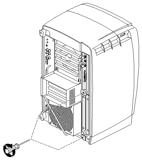
Gently tighten both captive screws in the plastic knobs, as shown in Figure 5-8. Be careful not to cross-thread these screws and do not over-tighten them.
Remove the wrist strap.
You are finished reinstalling the XIO Tri-Module.