This appendix summarizes technical specifications for SGI Graphics Cluster systems, in these sections:
Table A-1 shows the physical specifications for the SGI Graphics Cluster.
Table A-1. Rack Physical Specifications
Specification | Short Rack | Tall Rack |
|---|---|---|
Height | Operating: 96.5 x 61 x 94 cm (38 x 24 x 37 in.); 20 U | Operating:180.3 x 61 x 94 cm (71 x 24 x 37 in.); 36 U |
Weight | Operating maximum: 188 kg (414 lbs) | Operating maximum: 308.4 kg (680 lbs) |
Temperature | Operating: +5 °C (+41 °F) to +35 °C (+95 °F) | Operating: +5 °C (+41 °F) to +35 °C (+95 °F) |
Humidity | 20% - 80% RH, noncondensing | 20% - 80% RH, noncondensing |
Shock | Operating: Two shocks at 68 in/sec (6-in. drop
height), ten at 28 in./sec (1-in. drop) | Operating: Two shocks at 68 in/sec (4-in. drop
height), ten at 28 in./sec (1-in. drop) |
Vibration | Sine sweep 3-200-3 Hz, .50 G input at 1 oct/min. Random vibration: | Sine sweep 3-200-3 Hz, .50 G input at 1 oct/min. Random vibration: |
The tall rack comes with a 220-V power distribution unit (PDU); the short rack comes with either a 120-V PDU or a 240-V PDU. The PDU is rated as shown in Table A-2.
Table A-2. AC Power Specifications for Fully Loaded Systems
Classification | 120-V PDU in Short Rack, | 220-V PDU in Tall Rack, |
|---|---|---|
Voltage | 100-140 V; single-phase autoranging, 60 Hz | 200-240 V; single-phase autoranging, 60 Hz |
Current draw | 7.1 A | 6.01 A |
Maximum power consumption | 790 W | 1305 W |
Each node in the SGI Graphics Cluster has two system fans. Each processor in each node also has its own fan. The SGI Graphics Cluster Series 11 has one processor with a fan; the SGI Graphics Cluster Series 12 has two processors, each with a fan.
A fully configured SGI Graphics Cluster in a tall rack under maximum workload (1,305 W) can produce approximately 4,450 Btu/hour, requiring 0.3708 tons of cooling.
Air temperature measurements around the rack may vary.
Table A-3 shows the physical environment specifications for a node in the SGI Graphics Cluster.
Table A-3. Node Physical Specifications
Specification | Value |
|---|---|
System dimensions | Width: 42.9 cm (16.9 in.) |
Vibration | Operating: 0.38 mm (0.015 in.), 5-16.2 Hz; 0.2 G, 16.2-250 Hz Nonoperating: 0.6 G, 5-27.1 Hz; 0.4 mm (0.016 in.), 27.1-50 Hz; 2 G, 50-500 Hz |
Weight | 14.5 kg (32 lbs) (dual-CPU configuration) |
This section contains port pinout information for the following node ports, in these sections:
An SGI Graphics Cluster node uses a standard PS/2 keyboard port, as shown in Figure A-1.
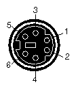
Table A-4 shows the cable pinout assignments for the keyboard port.
Table A-4. Keyboard Port Pinout
Pin | Assignment |
|---|---|
1 | Keyboard Data |
2 | (Reserved) |
3 | Ground |
4 | Keyboard Power (+5V) |
5 | Keyboard Clock |
6 | (Reserved) |
An SGI Graphics Cluster node uses a standard PS/2 mouse port, as shown in Figure A-2.
Table A-5 shows the cable pinout assignments for the mouse port.
The graphics card in the SGI Graphics Cluster node supports a DB15 HD video port and a DVI-D port.
Figure A-3 shows the DB15 HD port.
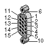
Table A-6 shows the port pinout assignments for the DB15 HD port.
Table A-6. DB15 HD Port Pinout
Pin | Assignment | Pin | Assignment |
|---|---|---|---|
1 | Red | 9 | No Connect |
2 | Green | 10 | Ground |
3 | Blue | 11 | Ground |
4 | Ground | 12 | IIC Data |
5 | Ground | 13 | Horizontal Sync |
6 | Red Return | 14 | Vertical Sync |
7 | Green Return | 15 | IIC Clock |
8 | Blue Return |
|
|
Table A-7 shows the cable pinout assignments for the DVI-D connector.
Pin | Assignment | Pin | Assignment |
|---|---|---|---|
1 | T.M.D.S. Data2- | 13 | T.M.D.S. Data3+ |
2 | T.M.D.S. Data2+ | 14 | +5V Power |
3 | T.M.D.S. Data2/4 Shield | 15 | Ground (for +5V) |
4 | T.M.D.S. Data4- | 16 | Hot Plug Detect |
5 | T.M.D.S. Data4+ | 17 | T.M.D.S. Data0- |
6 | DDC Clock | 18 | T.M.D.S. Data0+ |
7 | DDC Data | 19 | T.M.D.S. Data0/5 Shield |
8 | Not connected | 20 | T.M.D.S. Data5- |
9 | T.M.D.S. Data1- | 21 | T.M.D.S. Data5+ |
10 | T.M.D.S. Data1+ | 22 | T.M.D.S. Clock Shield |
11 | T.M.D.S Data1/3 Shield | 23 | T.M.D.S. Clock+ |
12 | T.M.D.S. Data3- | 24 | T.M.D.S. Clock- |
An SGI Graphics Cluster node serial port uses a standard PC-compatible pinout. The serial port supports data rates from 300 bits per second (bps) to 115.2 Kbps. Figure A-4 shows the serial port.
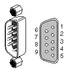
Table A-8 shows cable pinout assignments for the serial ports.
Pin | Assignment | Description |
|---|---|---|
1 | DCD | Data Carrier Detect |
2 | RD | Receive Data |
3 | TD | Transmit Data |
4 | DTR | Data Terminal Ready |
5 | SG | Signal Ground |
6 | DSR | Data Set Ready |
7 | RTS | Request to Send |
8 | CTS | Clear to Send |
9 | RI | Ring Indicator |
An SGI Graphics Cluster node uses a standard DB25 1284 EPC parallel port, as shown in Figure A-5.
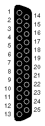
Table A-9 shows the cable pinout assignments for the parallel port.
Table A-9. Parallel Port Pinout
Pin | Assignment | Pin | Assignment | Pin | Assignment |
|---|---|---|---|---|---|
1 | Strobe | 10 | Ack | 19 | Ground |
2 | Data 0 | 11 | Busy | 20 | Ground |
3 | Data 1 | 12 | Error | 21 | Ground |
4 | Data 2 | 13 | Select | 22 | Ground |
5 | Data 3 | 14 | AutoFd | 23 | Ground |
6 | Data 4 | 15 | Fault | 24 | Ground |
7 | Data 5 | 16 | Init | 25 | Ground |
8 | Data 6 | 17 | SelectIn |
|
|
9 | Data 7 | 18 | Ground |
|
|
An SGI Graphics Cluster node has an RJ45 port for 10-Base-T or 100-Base-TX twisted-pair Ethernet. The port autoselects the speed (10 Mbps or 100 Mbps) and type (half-duplex or full-duplex) at bootup, based on what it is connected to. Figure A-6 shows the Ethernet port.
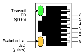
Table A-10 shows the cable pinout assignments for the Ethernet port.
Table A-10. Ethernet Port Pinout
Pin | Assignment |
|---|---|
1 | Transmit+ |
2 | Transmit– |
3 | Receive+ |
4 | (Reserved) |
5 | (Reserved) |
6 | Receive– |
7 | (Reserved) |
8 | (Reserved) |
The audio on the node motherboards is disabled in the SGI Graphics Cluster. The master node of the SGI Graphics Cluster Series 12 has a commercial audio card.
An SGI Graphics Cluster node uses a 3.5 mm mini jack stereo microphone port, an analog line-level audio input port, and an analog line-level audio output port.
For use with the audio card ports on the master node of an SGI Graphics Cluster Series12, SGI supports audio cables no longer than 3 meters. For uses requiring cables longer than 3 m, you can convert to balanced audio using an unbalanced-to-balanced converter such as Balance Buddy from Rane Corporation or FP-UBC2 from Radio Design Labs, or do active conversion to AES digital audio.
For port information for the sound card on the SGI Graphics Cluster Series12 master node, see the manufacturer's manual for the product, which is a SoundBlaster Live! Value sound card. You can download the manual for this card free from the manufacturer's web site, http://www.soundblaster.com.
Table A-11 shows the port pinout information for the mic-in, line-in, and line-out ports.
Table A-11. Mic-in, Line-in, Line-Out Port Pinouts
Connector | Tip | Ring | Sleeve |
|---|---|---|---|
Mic-in | L | R | Ground |
Line-in | L | R | Ground |
Line-out | L | R | Ground |
Figure A-7 shows the mic-in port.
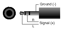
Figure A-8 shows the line level port.