This chapter contains information about hardware and specifications for your system.
This chapter does not contain detailed information on the system board. See the System Board Guide delivered with your system for detailed information on the system board and its components, BIOS, memory, slots and sockets, jumpers and connectors, and ports.
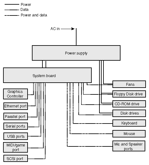
Figure 10-1 shows the power and data signals of the base unit components.
The following sections show EIDE and SCSI cable routings and connections to internal peripheral devices, and depicts standard and optional cables used in the system. For detailed information and location of bus connectors on the system board, see the System Board Guide.
 | Caution: When handling cables, flex them as little as possible. Ensure that cables do not contact sharp metal surfaces or become excessively bent or twisted. In particular, SCSI cables should not have any creased bends. |
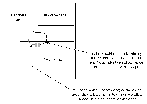
One EIDE cable connects the primary EIDE channel to the CD-ROM drive and (optionally) to another device in the peripheral device cage. Another EIDE cable can connect the secondary EIDE channel to one or two devices in the peripheral device cage.
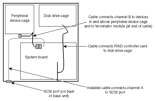
In a RAID system:
A SCSI cable connects Channel A of the on-board SCSI controller to the SCSI port on the back of the base unit.

Warning: For continued protection against fire and energy hazards, do not connect an external SCSI port to SCSI Channel B. Connect an external SCSI port only to SCSI Channel A. On some systems, a SCSI cable connects Channel B of the on-board SCSI controller to SCSI devices in and above the peripheral device cage.
A SCSI cable connects the SCSI connector on the RAID controller card to a SCSI connector on the back of the RAID disk drive cage.
In a JBOD ("just a bunch of disks") system:
A SCSI cable connects Channel A of the on-board SCSI controller to SCSI devices in and above the peripheral device cage and to the SCSI port on the back of the base unit.
Warning: For continued protection against fire and energy hazards, do not connect an external SCSI port to SCSI Channel B. Connect an external SCSI port only to SCSI Channel A. A SCSI cable connects Channel B of the on-board SCSI controller to disk drives in the JBOD disk drive cage.
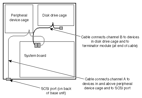
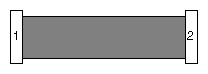
Table 10-1. Floppy Disk Drive Cable
Connector | Connects To |
|---|---|
1 | Floppy disk drive controller on system board |
2 | Floppy disk drive |
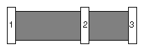
Table 10-2. EIDE Peripheral Device Cage Cables
Connector | Connects To |
|---|---|
1 | EIDE connector on system board |
2 | EIDE CD-ROM drive |
3 | EIDE device (optional)) |
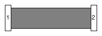
Table 10-3. RAID SCSI External Port Cable
Connector | Connects To |
|---|---|
1 | SCSI Channel A connector on system board |
2 | SCSI port on back of base unit |
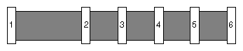
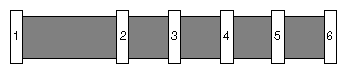
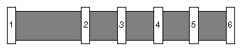
Table 10-4. RAID SCSI Peripheral Device Cage Cable
Connector | Connects To |
|---|---|
1 | SCSI Channel B connector on system board |
2, 3, 4, 5 | SCSI devices in or above peripheral device cage |
6 | SCSI terminator module |
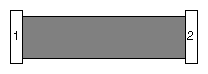
Table 10-5. RAID SCSI Disk Drive Cage Cable
Connector | Connects To |
|---|---|
1 | SCSI connector on RAID controller card |
2 | SCSI connector on back of disk drive cage |
The system has two power supplies for increased power supply reliability. Both must be connected to AC power for the system to operate correctly. However, if one power supply fails, you can replace it without shutting down the other power supply. This hot-swap capability lets you handle a power supply failure without shutting down and powering down the entire system.
Both power supplies provide 350 Watts of power to the system. Each power supply has a manual switch for selecting either 115 V AC (90-132 V AC) range or 230 V AC (180-264 V AC) range for domestic or international locations. The input frequency is 47-63 Hz, single phase. Input current is 6.0 A for the 115 V AC range and 3.5 A for the 230 V AC range. The typical efficiency is 70 percent at maximum output load.
The combined power supplies have the following DC output specifications. .
Table 10-8. Power Supply DC Output Specifications
Outputs → | 1 | 2 | 3 | 4 | 5 | 61 |
|---|---|---|---|---|---|---|
Nominal Output Voltages (VDC) | +5.02 | +3.32 | +12.0 | -12.0 | -5.0 | +5.0 |
Maximum Current Rating (ADC) | 30 | 15 | 12 | 0.5 | 0.5 | 1 |
Standby +5.0 VDC output voltage is always on.
Maximum +5.0 V and +3.3 V combined power is 150W.
The combined power supplies have a single power cable, P1 that connects to an ATX power connector on the system board.
The combined power supplies have four peripheral device power cables and one floppy disk drive power cable. Three of the cables have two peripheral device power connectors (P14 and P15) each. The fourth cable has two peripheral device power connectors (P12 and P13) and a floppy disk drive power connector (P11)..
Table 10-9. P1 Connector Pinout
Pin | Signal | Pin | Signal | Pin | Signal | Pin | Signal |
|---|---|---|---|---|---|---|---|
1 | +3.3V | 6 | +5.0 V | 11 | +3.3 V * | 16 | Ground |
2 | +3.3V | 7 | Ground | 12 | -12.0 V | 17 | Ground |
3 | Ground | 8 | Power Good | 13 | Ground | 18 | -5.0 V |
4 | +5.0V | 9 | 5.0 V Standby | 14 | Remote On | 19 | +5.0 V |
5 | Ground | 10 | +12.0 V | 15 | Ground | 20 | +5.0 V |
* + Sense
.
Table 10-11. P12 through P15 Connector Pinout
Pin | Signal | Pin | Signal |
|---|---|---|---|
1 | +12.0 V | 3 | Ground |
2 | Ground | 4 | +5.0 V |
The system has three 12 V DC cooling fans that are controlled by circuitry on the system board. A 120 mm (77 cfm) fan mounted behind the peripheral device cage and two 120 mm (77 cfm) fans mounted behind the disk drive cage ensure proper airflow to cool system components in the base unit. These fans bring cool air into the base unit to force out warm air. Another, smaller fan cools an area of the system board between the processors.
The cooling fans are field replaceable. See Chapter 9, “Servicing the System”for details on replacing the cooling fans.
| Caution: To maintain proper airflow to cool system components, make sure you install a new fan with the label on the fan motor facing toward the back of the base unit. |
Each power supply contains its own cooling fan. The power supply fans are not field replaceable. If a power supply fan requires replacement, you must replace the power supply. See Chapter 9, “Servicing the System” for details on replacing a power supply.
The system features advanced hardware monitoring and power management capabilities. These features help save energy, prolong system life, and provide for functionality such as remote system wakeup.
When used with Hardware Monitor software, these features enable you to keep track of such things as system voltages, component and chassis temperatures, and fan presence and operation. For more information on the items that can be monitored on your system, see the System Board Guide and Hardware Monitor Help.
See the System Board Guide for detailed information on the system board and its components.
Table 10-12. System Configuration Summary
Feature | Description |
|---|---|
Processors | One or two Intel SC242 (Slot 1) |
Processor Bus | 133 MHz, 64 bits |
Memory Modules | Dual inline memory modules (DIMMs) |
Memory Style | 168-pin DIMMs, 10 ns, 3.3V, registered/buffered, 72-bit (ECC) |
Memory Type | Synchronous Dynamic Random Access Memory (SDRAM) |
Memory Bus | 133 MHz, 128 bits |
Memory Size | 256 MB minimum, 6 GB maximum |
Memory Expansion | 256 MB, 512 MB, or 1,024 MB increments |
Graphics | AGP or PCI expansion card |
Audio | Creative AudioPCI controller, on system board |
SCSI | LSI dual-channel LVD Ultra3 SCSI controller, on system board Mylex RAID controller card for internal SCSI devices (RAID systems) |
Network | Intel 10/100 Mbps Ethernet adapter, on system board |
Disk Drives | LVD Ultra3 SCSI |
CD-ROM drive | 40X or higher EIDE ATAPI-compatible |
Keyboard | Windows 95/98 compatible PS/2 |
Mouse | Two-button wheel mouse |
Expansion Slots | One full-length AGP Pro Two fast-and wide PCI (66 MHz, 64 bits. 3.3 V/Universal) Four wide PCI (33 MHz, 64 bits, 5 V/Universal) One full-length ISA (card space shared with one wide PCI slot) |
Peripheral Device Cage | One 5.25-in x 1.6-in external bay for CD-ROM drive One 3.5-in x 1.0-in external bay for floppy disk drive Two internal/external bays for other peripheral devices; each bay accommodates one 5.25-in x 1.6-in device or one 3.5-in x 1.0-in device One 3.5-inch disk drive bracket above cage (some systems) |
Disk Drive Cage | Four slots for removable SCA LVD SCSI disk drives (RAID system) or four bays for LVD SCSI disk drives (JBOD system) |
I/O Ports | One PS/2 mouse and one PS/2 keyboard – 6-pin mini-DIN One parallel (LPT) – EPP/ECP, 25-pin DB25 Two serial (COM) – 9-pin DB9 Two Universal Serial Bus (USB) – 12 MB/sec One SCSI – Ultra3 Video – SVGA; others vary by controller Audio – Microphone, line in, line out, MIDI/game Network – Ethernet |
Power Supply | 350 Watts, manual-ranging Two supplies per system with hot-swap capability |
Table 10-13. System Specifications
Item | Specifications |
|---|---|
Dimensions | 10.5 in high x 16.7 in wide x 25.1 in deep (26.7 cm wide x 42.5 cm wide x 63.8 cm deep) |
Weight | 55 lb (25 kg) fully configured |
Equipment rack space required | 6U – 10.5 in (26.7 cm) |
Maintenance clearance | 36 inches (91.4 cm) front and back |
AC line voltage (US) | 90 – 132 VAC, 47 – 63 Hz, 1 phase, 15A/125 V receptacle |
AC line voltage (International) | 180 – 264 VAC, 47 – 63 Hz, 1 phase, 15A/250 V receptacle |
Power consumption | 324 W; 2.7 A at 120 VAC maximum configuration |
Recommended room temperature | 50° to 90° F (10° to 32° C); optimum 70° F (21° C) |
Recommended room humidity | 20% to 80% (non-condensing); optimum 50% |
Heat dissipation | 1,195 BTU/hr |