This chapter describes how to replace the major components of your system.
 | Warning: This is a user-serviceable system. Service and upgrade tasks should be performed by users who can follow instructions in a manual to service equipment, and can do so without harm to themselves or damage to the equipment. |
| Warning: The system is always on when connected to AC power. Before opening the system, disconnect the system's power cord from its AC power outlet. |
| Warning: Internal components may be at high temperatures. Allow time for them to cool before handling them. |
| Warning: Internal components can be damaged by static electricity. Use an antistatic wrist strap connected to the bare metal of the system's chassis to protect against electrostatic discharge. |
 | Note: “Right side” and “left side” are as seen from the front of the system. |
See Chapter 7, “Gaining Access to System Components” for details on opening the system and protecting against electrostatic discharge.
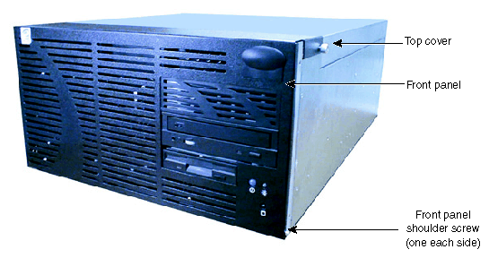
Remove the top cover. See Chapter 7, “Gaining Access to System Components”.
Install the new top cover.
Open the front panel. See Chapter 7, “Gaining Access to System Components” .
Remove the two shoulder screws at the bottom left and right corners of the front panel, and remove the front panel.
Align the bottom of the new front panel with the front of the unit, and reattach the two shoulder screws removed previously.
Close the front panel. See Chapter 7, “Gaining Access to System Components”.
The system disk drive is located in the uppermost part of the peripheral device bay, above the CD-ROM and floppy disk drives.
To replace the system disk drive:
| Warning: The system is always on when connected to AC power. Before performing this task, disconnect the system's power cord from its AC power outlet. |
| Warning: Mishandling a removed disk drive can cause the heads to crash! Subsequent failures may not be noticeable for three to six months. Handle disk drives carefully to avoid damage. |
Remove the top cover. See Chapter 7, “Gaining Access to System Components”.
Disconnect the power cable and SCSI cable from the disk drive.
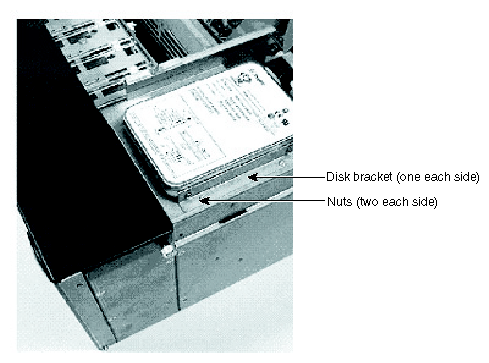
Remove the four nuts (two on each side) from the vertical screws on each side of the disk drive, and lift the disk drive out of the base unit.
Remove the two disk brackets from the disk drive and secure them to the new disk drive.
Replace the new disk drive in the base unit and secure it with the four nuts removed previously.
Connect the power cable and SCSI cable to the disk drive.
Replace the top cover. See Chapter 7, “Gaining Access to System Components”.
The CD-ROM drive, the floppy disk drive, and (optionally) another EIDE or SCSI device are located in the peripheral device bay, below the system disk drive. You can remove and replace any of these devices, and add a device if a bay is open, in the same way.
To add or replace a device in the peripheral device bay:
| Warning: The system is always on when connected to AC power. Before performing this task, disconnect the system's power cord from its AC power outlet. |
| Warning: The CD-ROM drive contains a laser and is classified as a Class 1 Laser Product. To prevent direct exposure to the laser beam and to avoid hazardous radiation exposure, do not try to open the CD-ROM drive enclosure. Return the drive to the manufacturer for repair. |
| Warning: Mishandling a disk drive can cause the heads to crash! Subsequent failures may not be noticeable for three to six months. Handle disk drives carefully to avoid damage. |
Remove the top cover and open the front panel. See Chapter 7, “Gaining Access to System Components”.
For ease of access, remove the rear fan. See “ Getting Support” in this chapter.
If removing or replacing the floppy disk drive, remove the CD-ROM drive first.
Disconnect the power cable and data cables from the device.
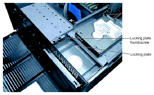
Loosen the thumbscrew on the locking plate.
Lift and hold the locking plate.
If adding a device to the open bay, pull the empty device tray out the front of the base unit.
If removing or replacing a device, pull the device out the front of the base unit.
If adding a device to the open bay, do one of the following:
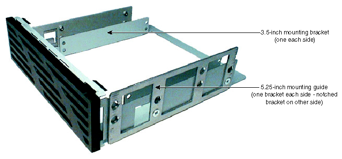
For a 3.5-inch x 1.0 inch device, secure it to the mounting brackets in the tray with screws on each side. Make sure the device's power and data connections face the open side of the tray.
For a 5.25-inch x 1.6-inch device or the floppy disk drive, remove the two mounting guides from the sides of the tray and secure them to the device with screws on each side. Make sure the guide with the notched side is on the left side of the device (as seen from the front).
If removing or replacing a device, remove the mounting guides from the old device and secure them to the new device with the same screws. Make sure the guide with the notched side is on the left side of the device (as seen from the front).
Set device ID and other settings as needed on the new device. See the label on the device for more information.
Lift and hold the locking plate.
Slide the device (in its tray or in its mounting guides) into the base unit.
Align the front slot in the left mounting guide with the tab on the locking plate.
Lower the locking plate.
Tighten the locking plate thumbscrew.
Connect the power and data cables to the device.
If removing or replacing the floppy disk drive, replace the CD-ROM drive.
Replace the rear fan. See “ Getting Support” in this chapter.
Replace the top cover and close the front panel. See Chapter 7, “Gaining Access to System Components”.
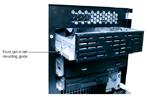
Up to four 3.5-inch x 1.0-inch SCSI disk drives may be installed in the disk drive cage at the front of the base unit. To add, remove, or replace disk drives, you must first remove the disk drive cage.
To add, remove, or replace a disk drive in the disk drive cage:
| Warning: The system is always on when connected to AC power. Before performing this task, disconnect the system's power cord from its AC power outlet. |
| Warning: Mishandling a disk drive can cause the heads to crash! Subsequent failures may not be noticeable for three to six months. Handle disk drives carefully to avoid damage. |
Remove the top cover and open the front panel. See Chapter 7, “Gaining Access to System Components”.
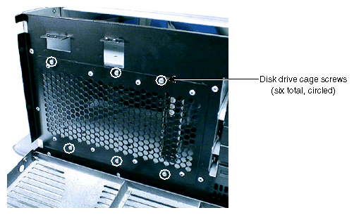
Remove the screws securing the disk drive cage to the base unit. See the following figure.
Pull the cage halfway out the front of the base unit.
Remove the power cables and data cables from any installed disk drives. Note the location of each set of cables so you can replace them later.
Pull the cage completely out the front of the base unit.
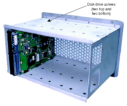
If removing or replacing a disk drive, remove the screws securing the drive to the cage, and then remove the drive from the cage.
If adding or replacing a disk drive, insert the drive in the cage and secure it with screws on both top and bottom. Make sure the drive's power and data connections face the open side of the cage.
Set device IDs and other settings as needed on the new drive. See the label on the drive for more information.
Replace the cage halfway into the base unit.
Connect the power cables and data cables to any installed disk drives.
Replace the cage completely in the base unit.
Secure the cage to the base unit with the screws removed previously.
Replace the top cover and close the front panel. See Chapter 7, “Gaining Access to System Components”.
The system board contains sockets in which expansion cards (such as the graphics controller card) are installed. See Chapter 8, “Upgrading the System” and the System Board Guide for more information on expansion cards and their sockets.
To avoid damaging an expansion card and voiding its warranty, take the following precautions:
Handle the expansion card only by the edges. Do not touch the metallic finger contacts.
Do not bend, twist, drop, or otherwise handle the expansion card carelessly.
Do not expose the expansion card to moisture or extreme temperatures.
Do not remove the expansion card from its antistatic package until you are ready to install it.
To replace an expansion card:
| Warning: The system is always on when connected to AC power. Before performing this task, disconnect the system's power cord from its AC power outlet. |
Remove the top cover. See Chapter 7, “Gaining Access to System Components”.
Disconnect any external and internal cables from the expansion card.
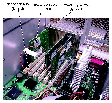
Remove and retain the retaining screw that secures the card to the card guide.
Pull the card straight out of its socket, and place the card on an antistatic surface.
Remove the new card from its antistatic package and slide it into the socket from which you removed the old card. Push the new card into the socket until it is firmly seated.
Secure the new card to the card guide with the retaining screw (6-32 x 0.25 hex head) removed previously.
Connect any internal and external cables to the new card.
Replace the top cover. See Chapter 7, “Gaining Access to System Components”.
The system board contains sockets for eight dual inline memory modules (DIMMs).
To avoid damaging a DIMM and voiding its warranty, take the following precautions:
Do not touch the metallic finger contacts.
Do not bend, twist, drop, or otherwise handle the DIMM carelessly.
Do not expose the DIMM to moisture or extreme temperatures.
Do not remove the DIMM from its antistatic package until you are ready to install it.
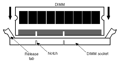
| Warning: The system is always on when connected to AC power. Before performing this task, disconnect the system's power cord from its AC power outlet. |
If replacing a DIMM, press the DIMM socket release tabs outward, away from each other; then grasp the top edge of the DIMM and pull it out of the socket.
Remove the new DIMM from its antistatic package. Verify the DIMM has gold-plated fingers that match the gold-plated socket contacts, and the slot keys on the DIMM match the slot keys in the DIMM socket.
Orient the DIMM so that the notches match the keys in the socket.
Push gently straight down until the release tabs snap into place.
Restart the system for the BIOS to detect the new memory.
For more information on DIMMs, DIMM sockets, and system memory configurations, see the System Board Guide.
On a system with only one processor, a processor bus terminator occupies the other processor slot on the system board. This module ensures proper termination for the processor bus; without it, the system will not function. When you add a second processor, you must remove this module and replace it with the new processor.
| Warning: The system is always on when connected to AC power. Before performing this task, disconnect the system's power cord from its AC power outlet. |
To remove the processor bus terminator:
Remove the top cover. See Chapter 7, “Gaining Access to System Components”.
Carefully pull the terminator card out of the processor slot.
Replace the top cover. See Chapter 7, “Gaining Access to System Components”.
For more information on the processor bus terminator, see the System Board Guide.
The system board contains sockets for two processor modules. Each processor module is secured to the system board with retention clips.
To replace a processor module:
| Warning: The system is always on when connected to AC power and the power supplies are switched on. Before opening the system, switch off both power supplies. |
Pull the locking tabs on the retention clips outward, and slide the processor module out of the retention clips and its slot.
Remove the new processor from its antistatic package, and align the processor module over the retention clips and the slot. The processor module is keyed and fits only one way.
Press the processor module down until it seats in the slot and the locking tabs on the retention clips click into place.
For more information on processors and processor socket locations, see the System Board Guide.
| Warning: There are no user-serviceable parts in the power supply. Return the power supply to the manufacturer for repair. |
The power supply is located in the upper section of, and is secured to the back of, the base unit chassis. See Chapter 10, “System Hardware and Specifications” for technical information on the power supply.
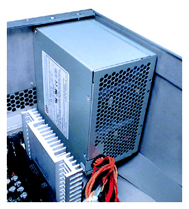
To replace the power supply:
| Warning: The system is always on when connected to AC power. Before performing this task, disconnect the system's power cord from its AC power outlet. |
Remove the top cover. See Chapter 7, “Gaining Access to System Components”.
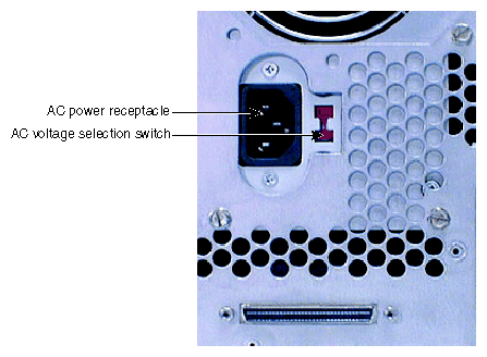
Disconnect the AC power cord from the AC power receptacle at the back of the base unit chassis.
Disconnect all power cables from all internal peripheral devices and the system board. Note the locations to which the power cables are connected:
Table 9-1. Power Cable Connections
Cable
Connects to
P1 and P2
ATX power connectors on the system board
P3 through P8
CD-ROM drive, disk drives, and other peripheral devices
P9
Floppy disk drive
Remove and retain the screws securing the power supply to the back of the base unit chassis.

Caution: Support the power supply as you remove the screws. Do not let the power supply fall or damage to equipment may result. Remove the power supply from its shelf and the base unit chassis.
Remove and retain the screws securing the mounting plate to the power supply.
Using the same screws, attach the mounting plate to the new power supply.
Place the new power supply and mounting plate into the base unit, and secure it with the screws removed previously.
Caution: Support the power supply as you replace the mounting plate screws. Do not let the power supply fall or damage to equipment may result. Make sure the AC voltage selection switch on the power supply (on the back of the base unit) is set to the proper line voltage for your location.
If your location uses 90 to 135 volts, the number 115 must be visible.
If your location uses 180 to 264 volts, the number 230 must be visible.
Warning: If you do not set the AC voltage selection switch on the power supply correctly, equipment damage may occur when you connect the system to AC power.
Connect the power cables to the system board and internal devices.
Connect the AC power cable to the AC power receptacle at the back of the base unit chassis.
Replace the top cover. See Chapter 7, “Gaining Access to System Components”.
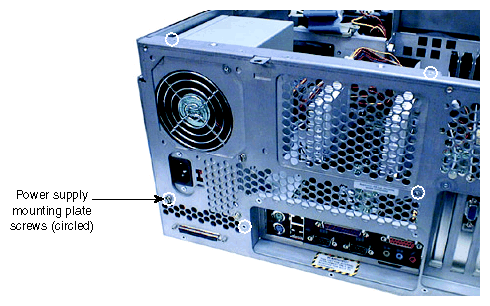
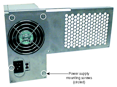
For more information:
On controlling system power, see Chapter 4, “Operating the System”.
On the power supply, see Chapter 10, “System Hardware and Specifications”.
A rear fan mounted behind the peripheral device bay and two front fans mounted behind the disk drive cage ensure proper airflow to cool system components in the base unit.
| Caution: To maintain proper airflow to cool system components, make sure you install a new fan with the label on the fan motor facing toward the back of the base unit. |
To replace the rear fan:
| Warning: The system is always on when connected to AC power. Before performing this task, disconnect the system's power cord from its AC power outlet. |
Remove the top cover. See Chapter 7, “Gaining Access to System Components”.
Disconnect the fan's cable from its connector on the system board.
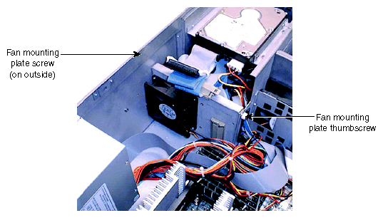
Remove and retain the screw securing the mounting plate to the base unit. See the following figure.
Loosen the fan mounting plate thumbscrew.
Note the airflow direction of the fan and the position of the fan on the mounting plate (the side closest to the processors), and gently pull upward on the mounting plate until the mounting plate and fan clear the base unit.
Remove and retain the screws attaching the fan to the mounting plate.
Ensure the airflow direction arrow on the new fan is pointing in the correct direction, then attach the new fan to the mounting plate using the screws removed previously.
Reinsert the mounting plate into the base unit, aligning the tabs on the bottom of the mounting plate with the slots in the base unit.
Tighten the fan mounting plate thumbscrew.
Tighten the screw attaching the mounting plate to the base unit.
Connect the new fan's cable to its connector on the system board.
Replace the top cover. See Chapter 7, “Gaining Access to System Components”.
To replace a front fan:
| Warning: The system is always on when connected to AC power. Before performing this task, disconnect the system's power cord from its AC power outlet. |
Remove the top cover. See Chapter 7, “Gaining Access to System Components”.
Disconnect the fan's cable from its connector on the system board.
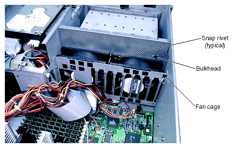
Remove the snap rivets holding the fan to the bulkhead.
Pull the fan up out of the fan cage, carefully guiding the power cable and connector out from under the bottom of the cage.
Route the power cable and connector of the new fan through the bottom of the fan cage, and lower the new fan into the cage.
Replace the snap rivets removed previously to secure the new fan to the bulkhead.
Connect the fan's cable to its connector on the system board.
Replace the top cover. See Chapter 7, “Gaining Access to System Components”.
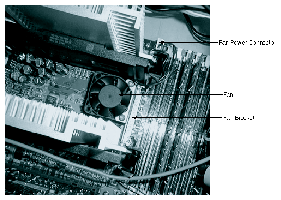
A small fan mounted between the two processors provides additional cooling for components on this area of the system board.
To replace the processor area cooling fan:
Disconnect the fan's cable from its connector on the system board.
Remove the screws securing the fan to the fan bracket, and remove the fan.
Secure the new fan to the fan bracket using the screws removed previously.
Connect the fan's cable to its connector on the system board.
Caution: The fan bracket is secured to the two processor retention clips with the nuts used to secure the retention clips to the system board. If you remove the fan bracket, make sure to remount it between the retention clips and the nuts, not between the retention clips and the system board.
See previous procedures in this chapter when necessary. See the System Board Guide for connector and socket locations.
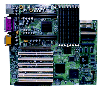
To remove the existing system board:
| Warning: The system is always on when connected to AC power. Before performing this task, disconnect the system's power cord from its AC power outlet. |
Remove the top cover. See Chapter 7, “Gaining Access to System Components”.
Note where all cables are connected to the system board, and then disconnect them from the system board.
Note where expansion cards are installed, and then remove them, placing them on an antistatic surface.
Remove the DIMMs, the processor modules, and the processor bus terminator (if installed), and place them on an antistatic surface.
Remove the nuts from the processor retention clips, and then remove the clips from the system board.
Remove the 13 screws from the system board.
Lift the system board out of the base unit and place it on an antistatic surface.
To install a new system board:
| Warning: The system is always on when connected to AC power. Before performing this task, disconnect the system's power cord from its AC power outlet. |
Connect the power switch/LED cable to connector J24 before installing the new system board.
Place the new system board into the base unit front edge first, and then lower the back edge into the base unit. Slide the system board toward the back of the base unit until all mounting holes are aligned with their standoffs.
Secure the new system board to the base unit using the 13 screws removed previously.
Secure the processor retention clips to the system board with the nuts removed previously.
Replace the DIMMs, the processors, and the processor bus terminator (if needed) in the appropriate sockets.
Replace the expansion cards in the appropriate expansion card sockets.
Reconnect the remaining cables to the system board.
Replace the top cover. See Chapter 7, “Gaining Access to System Components”.
The CMOS/clock lithium battery is located at the bottom of the system board, next to the lowest expansion card slots. The battery may be hidden under installed expansion cards.
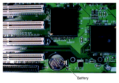
If you must replace the battery, the system will lose its operating parameters stored in CMOS memory. As a result, the system BIOS parameter settings are lost. After you replace the battery, you must reset the date and time and reconfigure the BIOS.
See the System Board Guide for detailed information on replacing the battery and on using BIOS Setup to configure the BIOS.
The power switch and the LEDs are mounted to the base unit behind the front panel. See the System Board Guide for connector and socket locations.
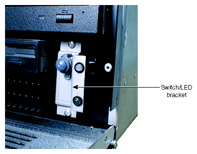
To replace the power switch or LEDs:
| Warning: The system is always on when connected to AC power. Before performing this task, disconnect the system's power cord from its AC power outlet. |
Open the front panel. See Chapter 7, “Gaining Access to System Components”.
Disconnect the power switch or LED cable (as appropriate) from the system board.
Remove the two screws attaching the switch/LED bracket to the base unit.
Gently pull the bracket away from the base unit. Do not rub the cables against the base unit edges.
If replacing the power switch, remove the screw securing the switch to the bracket, and then turn the switch until you can remove it from the bracket.
If replacing an LED, gently spread the clip and push the LED out of the bracket.
If replacing the power switch, insert the new switch into the bracket, and then turn it until you can secure it to the bracket with the screw removed previously.
If replacing an LED, push the new LED into its clip in the bracket.
Guide the cable beneath the peripheral bay and through the opening in the rear fan mounting bracket to the system board.
Connect the cable to the system board.
Replace the bracket on the base unit, securing it with the screws removed previously. Do not rub the cables against the base unit edges.
Close the front panel. See Chapter 7, “Gaining Access to System Components”.