This chapter describes how to set up the hardware for your system.
 | Warning: The base unit is heavy! To avoid personal injury or damage to equipment, use two persons to move the base unit. |
 | Caution: Remove and move items carefully. Do not drop items on a hard surface, or damage to internal components may result. You may need help to move heavy items. |
Remove everything from the shipping cartons and verify you have (at a minimum) these items:
System base unit and power cord
Rack-mounting hardware
Keyboard and mouse
Operating system software CD, diskettes, and documentation
Driver software CD
Monitor, power cord, and video cable (if purchased)
System documentation, including an Owner's Guide, a System Board Guide, and Release Notes (if provided)
Save the packaging materials. If you need to return equipment for repair, it must be in its original packaging for you to get warranty service.
When placing system components, keep these guidelines in mind:
Place the base unit in an area where air can circulate freely around it.
Do not expose the system to high levels of dust, smoke, or moisture.
Maintain a temperature range of 50 °F to 90 °F (10 °C to 32 °C); the optimum operating temperature is 70 °F (21 °C).
Maintain a humidity range of 20 percent to 80 percent non-condensing; the optimum humidity is 50 percent non-condensing.
Before mounting the base unit in an equipment rack in use at your site, prevent the rack from moving by engaging its stabilizers. If the rack is not equipped with stabilizers, refer to the rack documentation for stabilizing instructions.
Observe the following safety precautions when mounting the base unit in a rack in use at your site or when using the rackmount system:
Extend only one slide rail set at a time. Push an extended slide rail set back into the rack before extending another.
Warning: Extending more than one slide rail set could cause the rack to fall forward, causing damage to equipment and injury to anyone in front of the rack. Do not push on or lean against the rack. Always engage the stabilizers. The adjustable feet should be lowered securely against the floor.
If the rack contains an AC distribution box or an uninterruptible power supply (UPS), do not connect its the power cord to the wall outlet until instructed to do.
Set up the system completely before you start it.
Warning: Do not move the rack with equipment mounted or powered on, or damage to internal components may occur. Shut down the system, unplug the system power cords from their AC power outlets, remove all equipment, and then move the rack.
A vertical unit (U) is an industry-standard measurement for rackmount equipment. Small markers on the rack mounting rails usually indicate each vertical unit. For more information, see the documentation for the racks in use at your site.
You should determine the vertical mounting space within a rack enclosure taken up by each device you want to install. For example, an AC distribution box may require 1U or 2U of mounting space, while the system's base unit requires 5U of mounting space.
Note the following about vertical units:
A vertical unit (U) equals 1.75 in (4.45 cm) and consists of three mounting holes.
The mounting hole diameter is 7.1 mm (industry standard).
Mounting holes are counted upward after locating the first mounting hole within the range of vertical units required to install the equipment.
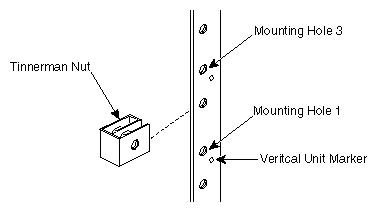
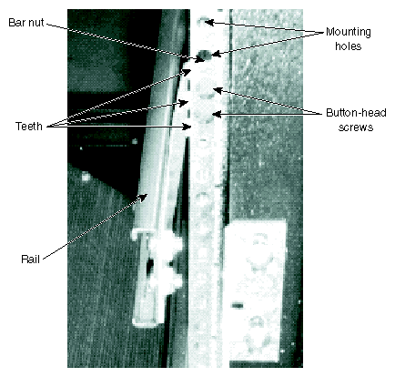
The following figure shows the typical installation of a tinnerman nut to mounting hole 3 of a vertical unit.
The following procedure describes how to mount the system's base unit in a typical 19-inch equipment rack. For detailed information on mounting equipment in a rack, see the documentation for the equipment racks in use at your site.
| Warning: The base unit is heavy! To avoid personal injury or damage to equipment, use two persons to mount the base unit in an equipment rack. |
To mount the base unit in an equipment rack:
Install the two handle brackets on the front of the base unit, using the screws provided.
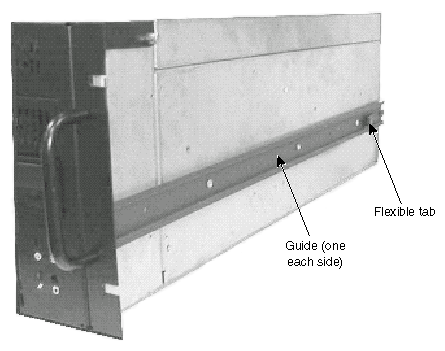
Remove the guide from each of the two rails. The guide is the innermost-sliding piece of the rails, and has a flexible tab at one end.
Attach a guide to each side of the base unit using the flat-head screws provided, making sure the flexible tab on the guide is toward the back of the base unit.
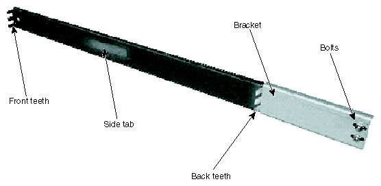
Use the button-head screws and bolts provided to loosely secure a bracket to each rail. The bracket has the teeth needed to secure the rail to the equipment rack. Install the button-head screws and bolts loosely so you can adjust the back teeth positions later.
The rackmount base unit requires 5U (10.5 in or 26.7 cm) of mounting space. Choose the five vertical units you need and, on the equipment rack mounting rails, mark the fifth and sixth mounting holes from the bottom of this 5U space.
Use the flat-head screws and bar nuts to secure the front teeth on both rails to the front mounting rails of the equipment rack.
With the flat side of each bar nut facing the screws, loosely install two flat-head screws to each bar nut, through the fifth and sixth mounting holes from the bottom of the 5U space. Slide the front teeth over the screws and tighten. Ensure the front teeth are between the bar nuts and the mounting holes.
On the front mounting rails on the equipment rack, slide tinnerman nuts over the third and thirteenth mounting holes from the bottom of the 5U space. The tinnerman nuts will be used when you secure the handle brackets on the front of the base unit to the front mounting rails of the equipment rack.
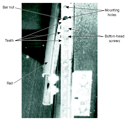
Use the button-head screws and bar nuts provided to secure the back rail teeth to the back mounting rails of the equipment rack.
With the flat side of each bar nut facing the screws, loosely install two button-head screws to the bar nut, through the fifth and sixth mounting holes from the bottom of the 5U space. Slide the back teeth over the screws and tighten. Ensure the back teeth are between the bar nuts and the mounting holes.
At the back of the equipment rack, tighten the screws and bolts on the brackets of each rail.
Extend the rails from the equipment rack until they lock.
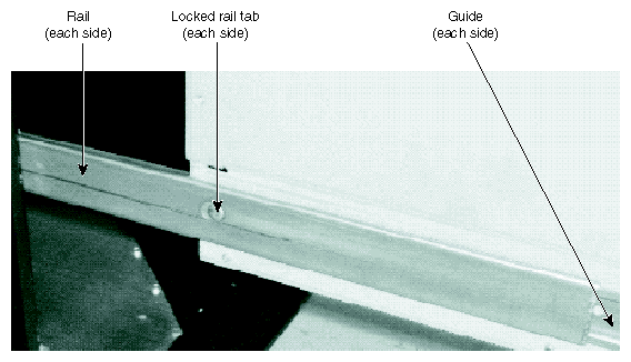
With a person on each side, lift the base unit and align the rails with the guides attached to the sides of the base unit. Slide the base unit into the rails until you hear a click. See the following figure.
Press the locked rail tabs and slide the base unit completely back into the equipment rack. After the base unit slides back a few inches, the base unit and rails slide together as a unit into the equipment rack. See the following figure.
Install the black screws through the handle brackets and the tinnerman nuts you installed previously to secure the base unit to the front mounting rails of the equipment rack.


| Caution: If you do not use the cables delivered with the system, use shielded cables to prevent excessive electromagnetic interference (EMI). The cables delivered with the system reduce the amount of EMI produced by the system. |
 | Note: You should disconnect the cables from the base unit before extending it from the rack, but if needed, you can extend the base unit without disconnecting the cables. Be sure there is enough cable to allow the base unit to fully extend from the rack. Use caution not to pinch the cables while extending or retracting the base unit. |
After placing the system components and mounting them in a rack in use at your site, connect them together using the included cables. The base unit and other system components have keyed and labeled ports, to make it easier to connect them together with the right cables. If you cannot connect a cable easily, ensure that you are aligning the cable connector correctly with the port.
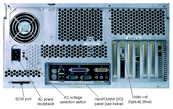
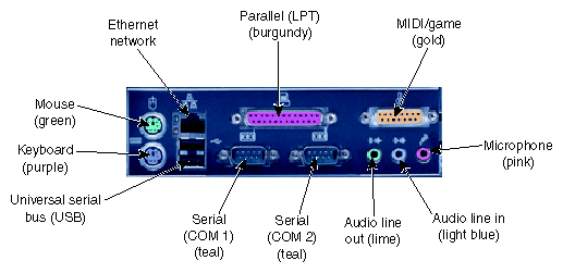
The following figures illustrate the back of the base unit. Most ports on the back of the base unit are colored and labeled with icons for easy reference. Locations of expansion cards and their ports may differ from those shown.
To connect the system components:
Connect a video cable from the monitor to the video out port on the graphics controller card. See the graphics controller documentation for more information.
Connect cables from the keyboard and the mouse to their ports.
Connect a cable from your site's Ethernet network to the Ethernet port.
Connect a cable from a parallel peripheral device to the parallel port.
Connect cables from any serial peripheral devices to the serial ports.
Connect cables from any USB peripheral devices to the USB ports.
Connect the cable from any external SCSI peripheral devices, or a SCSI terminator module, to the SCSI port. See “Connecting External SCSI Devices” in this chapter.
Caution: If you do not connect an external SCSI peripheral device to the SCSI port, connect a terminator module to the port. Connect cables to ports on any other installed expansion cards as required. See the expansion card documentation for more information.
Caution: Do not connect the system power cord to the base unit or to an AC power outlet at this time. See “Connecting to AC Power” later in this chapter for more information.
Expansion cards are installed as needed in the Accelerated Graphics Port (AGP), Peripheral Component Interconnect (PCI), and Industry Standard Architecture (ISA) expansion slots.
The following table describes the expansion slots and any typically installed expansion cards. Note that Slot 7 is a shared PCI/ISA slot; you can install a PCI expansion card or an ISA expansion card in this slot, but not both.
Table 1-1. Expansion Slots and Cards
Slot | Type | Typical Expansion Cards Installed |
|---|---|---|
1 (Left) | AGP | Graphics controller |
2 | PCI (64-bit/33 MHz) | Varies by system |
3 | PCI (64-bit/33 MHz) | Varies by system |
4 | PCI (64-bit/33 MHz) | Varies by system |
5 | PCI (64-bit/66 MHz) | Varies by system |
6 | PCI (64-bit/66 MHz) | Varies by system |
7 (Right) | PCI (64-bit/33 MHz) or ISA | Varies by system |
| Caution: If a modem card used in the system receives ground from the system, ensure the system is connected to an earth-grounded AC power outlet. |
For information on installing or connecting to expansion cards, see Chapter 8, “Upgrading the System” and the expansion card documentation delivered with the system.
The system has a dual-channel low-voltage differential (LVD) SCSI controller integrated on the system board. You can connect external Ultra, Ultra2, or Ultra3 SCSI devices to this controller through the SCSI port on the back of the base unit.
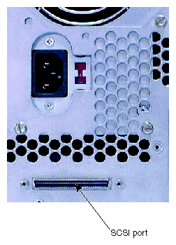
| Caution: If you do not connect an external SCSI peripheral device to the SCSI port, connect a terminator module to the port. |
To ensure data integrity and promote optimum performance:
Use the shortest cables possible to connect SCSI peripheral devices.
Use high-quality SCSI cables to ensure adequate shielding (impedance of 110 to 135 ohms).
To connect external SCSI devices:
If the system is connected to AC power and operating, shut down the system and unplug the system power cord from its AC power outlet.
If a terminator module is connected to the SCSI port on the system, remove it.
Connect one end of a SCSI cable to the SCSI port on the system.
Connect the other end of the SCSI cable to a SCSI peripheral device.
Connect a SCSI cable between SCSI ports on any additional SCSI peripheral devices.
Set the SCSI ID of each peripheral device to a unique SCSI ID number. Do not use any SCSI ID numbers already used by the system.
For each SCSI peripheral device connected to the port, if the device is:
The last or only device on the SCSI chain, install or enable SCSI termination
Not the last or only device on the SCSI chain, disable or remove SCSI termination
Ensure that the power switch on each peripheral device is in the off position; then connect the power cord from each peripheral device to an AC power outlet.
Turn on power to all connected SCSI peripheral devices, and then start the system.
If necessary, install software drivers and configure the peripheral devices according to the vendor's instructions.
See Chapter 8, “Upgrading the System” for additional details on installing external SCSI peripheral devices.
| Caution: The AC power cord for this unit is the service disconnect. To remove AC power from the system, you must unplug the system power cord from its AC power outlet. |
| Caution: Ensure the AC power outlet to which the system's power cord connects is close to the system and is easily accessible |
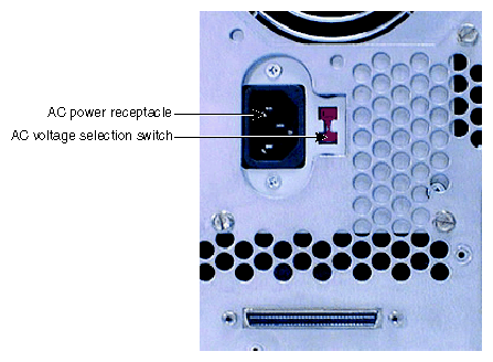
When you connect the system's base unit to AC power, auxiliary power is applied to the system. Auxiliary power ensures that system components power up quickly when needed. See Chapter 4, “Operating the System” for more information on controlling system power.
To connect the system to AC power:
Make sure the AC voltage selection switch on the power supply (on the back of the base unit) is set to the proper line voltage for your location.
If your location uses 90 to 135 volts, the number 115 must be visible.
If your location uses 180 to 264 volts, the number 230 must be visible.
Warning: If you do not set the AC voltage selection switch on the power supply correctly, equipment damage may occur when you connect the system to AC power.
Connect the system's power cord to the AC power receptacle on the base unit.
Connect the power cords from the monitor, base unit, and any external peripheral devices to properly grounded three-prong AC power outlets.
| Caution: If you start the system, and then turn it off before completing the instructions in Chapter 2, “Setting Up the Software” you will have to reinstall the operating system and associated system software. See “ Getting Support” for more information. |
| Caution: Before starting the system for the first time, you may want to learn more about system power, startup, and shutdown. See Chapter 4, “Operating the System” for more information. |
To start (apply full power to) the system, press the Power button on the front of the base unit.
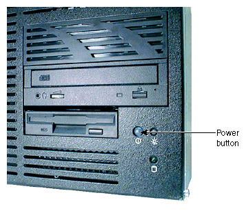
You can do the following to prepare your system for use:
If you want to get going with the default setup, go to Chapter 2, “Setting Up the Software” to start the system and go through operating system Setup. If you start the system and then turn it off before completing operating system Setup, you will have to reinstall the operating system and associated system software.
The operating system is already installed through the first phase of the Setup process. If you want to reload the operating system and associated system software instead of completing Setup, see Chapter 6, “Reinstalling the Operating System”.