The SGI Graphics Cluster provides low-cost semi-immersive graphics capabilities for visual simulation and virtual reality applications. The product is available in two models, the SGI Graphics Cluster Series 11 and the SGI Graphics Cluster Series 12. Each model consists of a single master node, multiple visual channel nodes (each with a commercial graphics card), and full Ethernet backbone, including a network switch, and can be ordered with multiple options. The SGI Graphics Cluster uses either the Linux or Windows NT operating system and incorporates proprietary hardware and software from SGI.
Each model of the SGI Graphics Cluster is available in a short rack format with one master node, a network switch, with a minimum of two channel nodes and a maximum of three channel nodes, or in a tall rack format with one master node, a network switch, with a minimum of two channel nodes and a maximum of seven channel nodes.
This guide provides basic system setup information, in these sections:
-

Caution: For information on adding nodes or replacing system components, follow instructions and safety procedures in SGI Graphics Cluster Hardware User's Guide.
Manuals for the SGI Graphics Cluster are available on the SGI Graphics Cluster Documentation CD included with the system. To obtain SGI documentation using the World Wide Web, see the SGI Technical Publications Library at http://techpubs.sgi.com. Enter a keyword search, or search by title to find the information or manual you need.
Table 1-1 shows the physical specifications for the SGI Graphics Cluster.
Table 1-1. Physical Specifications for SGI Graphics Cluster
Specification | Short Rack | Tall Rack |
|---|---|---|
Height | Operating:180.3 cm x 61 cm x 94 cm | Operating: 96.5 cm x 61 cm x 94 cm |
Weight | Operating maximum: 188 kg (414 lbs) | Operating maximum: 308.4 kg (680 lbs) |
Temperature | Operating: +5 °C (41 °F) to +35 °C (95 °F) | Operating: +5 °C (41 °F) to 35 °C (95 °F) |
Humidity | 20% to 80% RH, noncondensing | 20% to 80% RH, noncondensing |
Shock | Operating: Two shocks at 68 in/sec (6-in. drop height),
ten at 28 in/sec (1-in. drop) | Operating: Two shocks at 68 in/sec (4-in. drop height),
ten at 28 in/sec (1-in. drop) |
Vibration | Sine sweep 3-200-3 Hz, .50 G input @ 1 oct/min. Random vibration: | Sine sweep 3-200-3 Hz, .50 G input @ 1 oct/min. Random vibration: |
The tall rack comes with a 220-V power distribution unit (PDU); the short rack comes with either a 120-V PDU or a 220-V PDU. The PDU is rated as shown in Table 1-2.
Table 1-2. AC Power Specifications for Fully Loaded Systems
Classification | 120-V PDU in Short Rack | 220-V PDU in Tall Rack |
|---|---|---|
Voltage | 100-140 V | 200-240 V |
Current draw | 7.1 A | 6.01 A |
Maximum power consumption | 790 W | 1305 W |
 | Note: Fully loaded systems are defined as having a master node, the full complement of channel nodes (three for the short rack, seven for the tall rack), the system standard Ethernet switch, an optional gigabit Ethernet switch, and all necessary cabling. |
After the rack is set up, start the system by following these steps:
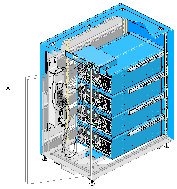
Open the rear door of the rack. Check that the power cord of each node is plugged into the rack's power distribution unit (PDU). See Figure 1-1.
Find the bag of keys that is attached to the inside of the rack frame inside the rear door. (The bag contains two keys for each node; all keys are identical.)
If the monitor, keyboard, and mouse included with the SGI Graphics Cluster are not already cabled to the master node, cable them; see Figure 1-2 for connectors.
Note: Audio ports on the SGI Graphics Cluster motherboard are disabled. For more information on system audio, see SGI Graphics Cluster User's Guide. Connect the monitor cabled to the master node to a power source.
Cable other monitors and other peripherals and options to which the system is to be connected; see Figure 1-2 for connectors on the node rear panel.
On the master node of an SGI Graphics Cluster Series 12 running Linux, the following applies:
If an optional network interface PCI card (NIC) is present, it is eth0 and the onboard NIC is eth1.
If an optional gigabit Ethernet card is present, it is the last NIC (eth1 or eth2).
Power on the rack PDU with its circuit breaker; see Figure 1-1.
On each node, unlock the node bezel.
Pull the bezel out and away from the node, and swing the bezel down, as shown in Figure 1-3.
Power on the monitor connected to the master node. Power on other peripherals as desired.
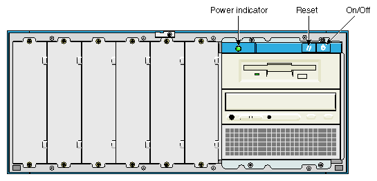
Turn on the master node, which is the lowest node in the rack. The green power indicator LED on the front panel illuminates. Figure 1-4 shows the front controls and the power status LED.
The Num Lock, Scroll Lock, and Caps Lock LEDs on the master node's keyboard flash briefly. The system starts and displays a boot message on the monitor connected to the master node.
Note: If the power indicator LED illuminates but the SGI splash screen and boot information do not appear on the master node monitor, press the reset button. If the system does not turn on or boot after you press the power button, see the next section for the possible causes of the boot failure. Turn on each channel node. Close the bezel for each node. Close the rack rear door.


SGI has set up a cluster administration account, gcadmin, for your use. The password is sgisgi. Each channel is set to autologin to the gcadmin account, and displays a desktop when the system is fully booted.
SGI provides the command-line tool pconsole, which enables the administrator to execute commands on all channels in unison. Documentation for pconsole is in /usr/share/doc/pconsole.
SGI also preloads several tools that you may find useful:
. pcp: Performance Co-Pilot
. rsync: remote file transfer tool
. autologin: allows automatic login upon boot
. wu-ftpd: FTP daemon
. ntp: network time protocol
Documentation for these tools and others on the system disk are on the system disk in /usr/share/doc. The license for SGI Performer is included in a packet.
For further Linux configuration information, see Linux in a Nutshell, by Ellen Siever, Stephen Spainhour, Jessica P. Hekman, and Stephen Figgins, third edition, O'Reilly & Associates, 2000; ISBN 0-596-00025-1.
You must install Windows NT to meet the acceptance requirements of Microsoft EULA. All drivers, and Service Pack 6a are installed during the this procedure. The Windows NT license is included with the operating system packet.
SGI suggests following accepted Windows NT administration procedures for setting up networking and domain controllers. Subnetworks that meet RFC specifications are available for 10.0.2.xxx and 192.168.1.xxx.
For further Windows NT configuration information, see Windows NT in a Nutshell, by Eric Pearce, O'Reilly & Associates, 1997; ISBN 1-56592-251-4, or Essential Windows NT System Administration, second edition, AEleen Frisch, O'Reilly & Associates, 1998; ISBN 1-56592-274-3.
SGI recommends that you use the address xxx.xxx.xxx.1 for the master channel, and start the IP addresses at xxx.xxx.xxx.10 for channel0, the first channel node. This scheme provides an easy-to-remember correlation between channel host names and the internal IP addresses on the network. For example:
Master channel (master-channel): 192.168.1.1
channel0: 192.168.1.10
channel1: 192.168.1.11
channelx: 192.168.1.1x
Official channel names are as follows:
master-channel
channel0
channel1
channel2
channel3
channel4
channel5
channel6
If the system does not boot after you have applied power, check the following factors that might have caused the boot failure.
The rack's external power cable may be loosely connected.
Check the power cable connection from the power source to the rack PDU. Make sure that each cable is properly connected to each power supply.
The node's power cable may be loosely connected.
Check the node power cable connection from the node to the rack PDU.
No power comes from the grounded power outlet.
Ask an electrician to check your power outlet.
Note: If you have performed the preceding actions and the system still fails to boot, ask your service provider or a qualified technician for assistance.
Observe the following safety guidelines:
Before you add equipment to a rack, be sure to power off the rack, disconnect the power cord, and pull out the anti-tip tray at the bottom of the rack.
When adding or servicing equipment in the rack, do not pull out more than two nodes at a time.
Follow electrostatic discharge (ESD) precautions when you handle components or do work inside a node. Electronic equipment can be irreparably damaged by ESD. Always follow these preventative measures when handling a system component:
Remove a component from its antistatic bag only when you are about to install it.
If you must handle a component before installation, do not place it on surfaces that produce ESD (carpeting, for example), or near devices that create static electricity.
Attach a wrist grounding strap before handling electronic components. Wrist grounding straps are available at most electronic component stores.
Note: Carefully follow all instructions in the SGI Graphics Cluster User's Guide for adding or replacing nodes or system components.