This section provides a general, technical description of the SGI Origin 3000 server series hardware architecture, especially as it relates to configuration issues.
The SGI Origin 3000 series systems are distributed shared memory (DSM) computer systems that scale from 2 to 512 processors. In a DSM system, each processor contains memory that it shares with the other processors in the system. The modularity of the DSM systems combine the advantages of low entry-level cost with global scalability in processors, memory, and I/O. Table 2-1 lists the system configuration ranges for the SGI Origin 3000 series system.
Initial SGI Origin 3000 series systems use the MIPS R12000 processor that is a 64-bit RISC, superscalar processor with speculative branching, out-of-order execution, and a 400-MHz operating clock speed.
Four processors, each with 8 Mbytes of private secondary cache, are connected at a Bedrock (refer to Figure 3-1). This Bedrock ASIC acts as a crossbar between the processor interface, local memory interface, the network interface, and the I/O interface.
Four Bedrocks, each supporting four processors, connect to an eight-port router that can connect up to 32 routers in a maximum 4 x 4 x 32 extended hypercube topology.


The SGI Origin 3000 series tall rack can house the following standard 19-inch rackmounted subassemblies: C-brick, D-brick, G-brick, I-brick, P-brick, R-brick, X-brick, and power bay. The tall rack is used by SGI Origin 3200C, SGI Origin 3400 and SGI Origin 3800 systems. The outer dimensions of the tall rack with casters, side panels, and decorative doors does not exceed 74 in. high × 30 in. wide × 50 in. deep.

Main features of the tall rack:
19-inch EIA standard mounting rails
39 U of space (1U = 1.75 inch)
Mounted on casters
All subracks must provide self cooling with airflow from front to rear
Power distribution strip (PDS), 200-250 Vac, 10 A, single-phase power for D-bricks and third-party equipment
The SGI Origin 3000 series short rack can house the following standard 19-inch rack mounted subassemblies: C-brick, D-brick, I-brick, P-brick, X-brick, and power bay. The short rack is used by SGI Origin 3200 systems. The outer dimensions of the short rack with casters, side panels, and decorative doors does not exceed 36 in. high × 26 in. wide × 41.5 in. deep.
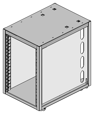
Main Features of the short rack:
19-inch EIA standard mounting rails
17 U of space (1 U = 1.75 inch)
Mounted on casters
All subracks must provide self-cooling with airflow from front to rear
One power distribution strip (PDS), 200-250 Vac, single-phase, 10 A, power for the power bay, D-bricks, and third-party equipment
The power bay houses from two to six hot-swap, distributed power supplies (DPSs). It supplies AC power to the DPSs and provides power control and monitoring. A minimum of two DPSs must be present at all times to provide standby 48-Vdc power. The outputs of the DPSs are bused together to provide 4750 watts of available power in an N+1 redundant configuration. DPSs are added when additional subracks are added to the configuration.


Main Features of a power bay:
Height: 3 U
Dimensions in inches: 5.1 H × 17.5 W × 24.5 D
Weight: 72 lbs (fully loaded with 6 power supplies)
Provides 4.75 KW continuous N+1 power
Provides eight 48-Vdc power output connections that use 21-pin Foxconn connectors
Main Features of a Distributed Power Supply:
Installs from the front of the rack
Dimension in inches: 5.0 H × 2.8 W × 13 D
Approximate weight of 7.5 lbs
Rated at 950 W maximum output power
The SGI Origin 3400 and SGI Origin 3800 systems support five types of PDUs (refer to Table 3-1). The PDUs protect against over-current conditions and provide an on/off switch to remove power from the rack.
 | Note: The SGI Origin 3200 systems do not use PDUs; instead they use a power distribution strip. |
Customer sites that use single-phase power require one single-phase PDU for each power bay. Customer sites that use three-phase power require one three-phase PDU for each rack.
The physical dimensions of the PDU enclosure are 4 × 5 × 10 inches. It mounts in the lower cable management area in the rear of the tall racks.
Marketing Code | Destination Location | Power Cord | Input Power Connector |
|---|---|---|---|
DK-N1P-003 | Domestic, Mexico, Canada, and Japan | UL Listed Cord | NEMA L6-30 1Ph 30A Plug 208/240 VAC |
DK-N1P-001 | Domestic, Mexico, Canada, and Japan | UL Listed Cord | IEC 60309 1Ph 30A Plug 208/240 VAC |
DK-1P-002 | Europe and other | 32A Harmonized Cord | IEC 60309 1Ph 32A Plug 208 / 240 VAC |
DK-N3P-001 | Domestic, Mexico, Canada, and Japan | UL Listed Cord | IEC 60309 3Ph 60A Plug 200/240 VAC |
DK-N3P-002 | Europe and other | 5 Wire Harmonized Cord | IEC 60309 32A 3Ph Plug 400 VAC |

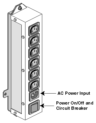
All SGI Origin 3000 series systems use power distribution strips. In the SGI Origin 3200 short rack the PDS provides:
AC power distribution to the power bay
AC power to a D-brick
AC power to third party equipment
Over-current protection for all equipment in the short rack
An on/off switch to remove power from the short rack
In SGI Origin 3400 and SGI Origin 3800 tall racks the PDS provides:
AC power to a D-brick
AC power for third party equipment
Over-current protection for a D-brick and third party equipment
An on/off switch to remove power from D-bricks and third party equipment
In both the short rack and tall rack, the PDS is located on the inside rear wall. Its dimensions are 12 × 2.5× 3.5 inches. In a short rack, a three-meter power cord connects the PDS to either the AC wall or underfloor outlet. In a tall rack, a 1.5-meter power cord connects the PDS to the PDU.
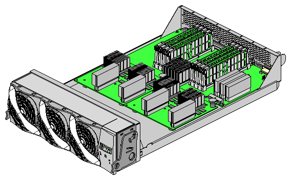
The C-brick is a 3-U-high 19-inch rackmountable enclosure that contains:
Either two or four 64-bit RISC processors with an 8-MB secondary cache
Eight DIMM slots; each DIMM pair has two banks of memory
Node electronics
One L1 controller
The node electronics, L1 controller, and power regulators are contained on a single printed circuit board (PCB). The processors and cache are housed on separate PIMM boards. Each PIMM contains two processors and secondary cache. Figure 3-9 shows the block diagram of a C-brick.

The C-brick has the following electrical features:
Configurable as either a 2-processor or 4-processor node
Configurable from 512 Mbytes to 8 Gbytes of main memory
Contains one 8-Mbyte secondary cache per processor
Contains one 1.6-GB/s (each direction) NUMAlink channel
Contains one 1.2-GB/s (each direction) Xtown2 channel
Contains one USB port that connects to the L2 controller (optional in SGI Origin 3200 systems)
Contains one console port with DB9 connector
Figure 3-10 shows a front view of the C-brick logic carrier (the assembly that holds the C-brick components).
The C-brick has the following mechanical features:
Two 400-MHz MIPS R12000 processors and 8-MB of secondary cache are mounted on a PCB. This assembly is called the processor-integrated memory module ( PIMM).
The MIPS R12000 processor has the following features:
64-bit RISC design, 0.25-micron CMOS process
Single-chip superscalar RISC dataflow architecture
8-MB secondary cache
32-KB 2-way set-associative data cache
32-KB 2-way set-associative instruction cache
2,048-entry branch prediction table
48-entry active list
32-entry two-way set-associative branch target address cache (BTAC)
Doubled secondary cache prediction table for improved hit rate
Improved branch prediction by using global history mechanism
Maintains code and instruction set compatibility with the MIPS R10000
Main memory consists of up to eight banks per node; each bank is split between two DIMMs of a DIMM pair with each DIMM pair supporting two banks. Memory must be increased or decreased in two-DIMM increments. The reason for this is that a single bank of memory is contained on two DIMMs and the memory size must be increased or decreased in whole banks. The DIMMs that make up a single bank must be the same memory size; however, each DIMM pair within a brick can be a different memory size. Refer to Table 3-2 for the main memory size matrix. This table does not include systems that have multiple-size memory banks. Refer to Table 8-1 for memory sizes that use mixed size memory DIMMs.
The clock speed of the memory parts is 100-MHz address and 200-MHz data, which produces a memory bandwidth of 3200 MB/s.
Table 3-2. Main-memory DIMM Sizes
DRAM Technology | Single | Minimum
Increment | 1 DIMM Pair Installed | 2 DIMM Pairs Installed | 3 DIMM Pairs Installed | 4 DIMM Pairs Installed |
|---|---|---|---|---|---|---|
128 Mbits | 256 Mbytes | 512 Mbytes | 512 Mbytes | 1 Gbytes | 1.5 Gbytes | 2 Gbytes |
128 Mbits | 512 Mbytesa | 1 Gbytes | 1 Gbytes | 2 Gbytes | 3 Gbytes | 4 Gbytes |
256 Mbits | 1 Gbytesa | 2 Gbytes | 2 Gbytes | 4 Gbytes | 6 Gbytes | 8 Gbytes |
[1]
There are two DIMM types used:
Standard memory DIMM - for systems with a maximum of 128 processors
Meta memory DIMM - Contains one additional memory chip per DIMM to provide additional directory memory for building configurations larger than 128 processors. Customers who plan to upgrade their systems beyond 128 processors should order the meta memory DIMMs. The cost to remove the existing standard memory and replace it with meta memory is high.
Note: SGI Origin 3000 series DIMMs are not compatible with the DIMMs used in SGI Origin 200, SGI Origin 2000, or SGI Octane systems.
The D-brick is a 4-U high disk enclosure that supports JBOD (just a bunch of disks) and RAID within an SGI Origin 3000 series rack.
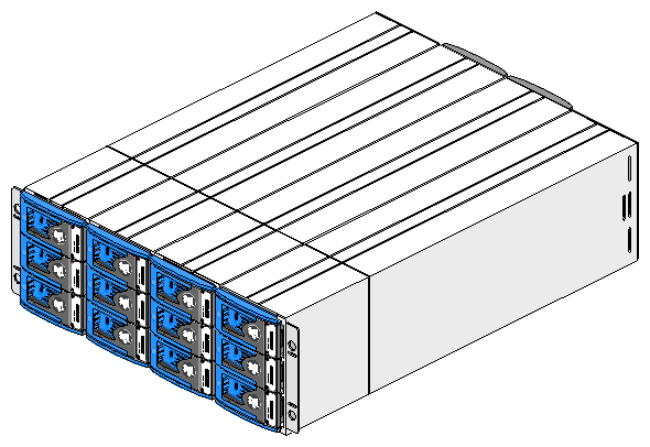
The SGI TP-9100 storage system is another storage solution for SGI Origin 3000 series systems. For more information about the SGI TP-9100 storage system, refer to the SGI Total Performance 9100 Storage System Owner's Guide, publication number 007-4068-xxx.
The D-brick has the following features:
Height: 4 U
Weight: 94 lbs (fully loaded)
Dimensions in inches: 6.95 H × 17.50 W × 23.00 D
Maximum number of disk drives: 12
Requires a minimum of two disk drives
Mounts in a standard 19-inch rack
Occupies a fixed position; does not slide out
Input power is 200 to 230 Vac single-phase, 50/60 Hz
Typical power consumption is 400 VA or less
The I-brick provides the boot I/O functions for all SGI Origin 3000 series systems. It supports five hot-pluggable PCI cards, two sled-mounted 3.5 inch Fibre Channel disk drives, and a specialized slot for a CD-ROM. The five hot-pluggable PCI slots support full-length cards with 64-bit data/addressing. Refer to Figure 3-12 for the I-brick block diagram.
The five PCI slots are configured on two buses: bus 1 supports three 33-MHz PCI slots and bus 2 supports two 66-MHz PCI slots. Separate buses enable the I-brick to run 33-MHz and 66-MHz devices in the same brick. Various types of PCI cards can be used in the I-brick, such as SCSI, Fibre Channel, ATM, Gigabit Ethernet, etc. Refer to Table 4-7 for a list of supported PCI cards.
The I-brick also provides access to a network via a 10/100BaseT Ethernet port, and access to peripherals via one 1394 channel and two USB channels. Refer to Chapter 7, “Configuration Guidelines” for configuration guidelines.
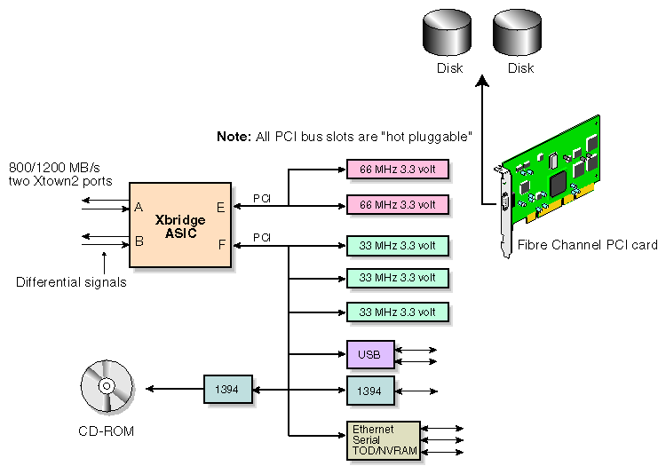
Figure 3-13 shows a rear view of the I-brick with the cover removed.

The I-brick has the following electrical features:
The I-brick has the following mechanical features:
Height: 4 U
Weight: 69 lbs (fully loaded)
Dimensions in inches: 6.64 H × 17.50 W × 27.74 D
Hard mounts in a standard 19-inch rack (does not slide out of the rack)
Supports a CD-ROM
Supports five 3.3-Vdc PCI cards (3 PCI cards at 33 MHz and two PCI cards at 66 MHz)
Note: One of the five PCI slots is reserved for a Fibre Channel disk controller. Supports two 3.5-inch sled-mounted Fibre Channel disk drives
Input power is +48 Vdc (~190 watts)
The P-brick is a Crosstalk-to-PCI based I/O expansion subsystem that supports a maximum of 12 hot-pluggable PCI cards. It has two Xtown2 ports (1.2 GB/s each direction); each Xtown2 port can connect to an Xtown2 port on a C-brick. The 12 PCI slots are configured on six buses; each bus supports two 33- or 66-MHz slots.
Refer to Table 4-7 for a list of supported PCI cards and to Chapter 7, “Configuration Guidelines” for configuration guidelines.
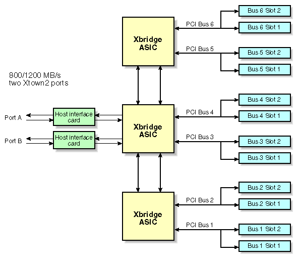
Figure 3-15 shows a rear view of a P-brick with the cover removed.

The P-brick has the following electrical feature:
Two Xtown2 ports (1.2 GB/s each direction)
The P-brick has the following mechanical features:
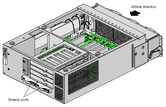
The X-brick is an I/O expansion brick; it contains four XIO slots that support many XIO cards when used with SGI Origin 3000 servers. This enables existing Origin customers to migrate their XIO cards to the SGI Origin 3000 series systems. Not all SGI XIO adapters will be supported in the X-brick, so please refer to Table 4-6 for a list of supported XIO adapters.
The X-brick has two Xtown2 ports (800 MB/s each direction); each Xtown2 port can connect to an Xtown2 port on a C-brick.
Refer to Figure 3-16 for the X-brick block diagram.

Figure 3-17 shows a rear view of the X-brick with the cover removed.
The X-brick has the following electrical feature:
Two Xtown2 ports (800 MB/s each direction)
The X-brick has the following mechanical features:
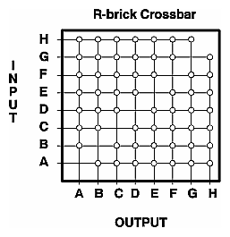
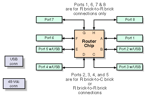
The R-brick is an eight-port crossbar that connects any input-link channel to any of seven possible output-Link channels. It contains a router ASIC that is mounted on a PCB with its associated power circuitry, L1 controller, and a USB hub. The hub fans out USB signals from the L2 controller to the L1 controller inside the R-brick and to the four nodes (C bricks) that may be connected to the router.
The R-brick has a total of eight 100-pin link connectors located on its rear panel. Four of these connect to C-bricks and carry USB signals as well as link signals. The others are only for connection to other routers and do not carry USB signals. Refer to Figure 3-19. Metarouters and repeat routers use all eight ports to connect to other R-bricks.
When an R-brick-to-R-brick connection is made through ports that carry USB signals, the USB signals are ignored. USB signals to the C-bricks are distributed over the network cables. Because an R-brick can have a maximum of four C-bricks attached to it, only four of the R-brick's 100-pin network connectors have USB signals routed to them. Ports 2, 3, 4, and 5 carry USB signals. Therefore, a C-brick must connect to an R-brick via port 2, 3, 4, or 5.
Each R-brick has a dedicated USB connection to the L2 controller through a 4-pin USB connector on its rear panel. Therefore, it is not necessary for an R-brick to distribute USB signals to other R bricks. R-brick-to-R-brick network connections are normally made through the four port connectors that do not carry USB signals; however, they are not restricted to these four ports.
The R-brick has the following electrical features:
The R-brick has the following mechanical features:
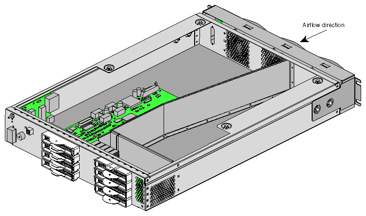
Figure 3-20 shows a rear view of the R-brick enclosure with the cover removed.
The G-brick is a graphics subsystem that can be scaled from 1 to 8 pipes (eight G-bricks in a system). The G-brick is 18 U high and is rackmounted in a SGI Origin 3000 series rack. Each G-brick has one 2RM port and one 4RM port. The higher the number of RMs (Raster Managers) per port the higher the performance of the pipe. The G-brick is the base graphics used in the SGI Onyx 3000 family of visualization systems.
Each tall rack can hold from one to two G-bricks. Each pipe of a G-brick connects to a Xtown2 channel of an I- or X-brick via a NUMAlink cable. The G-brick's input power cord plugs into the AC wall outlet and the L1 controller is connected to a L2 controller via a USB cable. If a G-brick is in a rack that does not have an L2 controller, a USB hub can be used to pass the system controller information to an L2 in an adjacent rack.

An SGI Origin 3000 series system supports a wide range of peripherals to deliver unmatched performance for large supercomputing workloads. Refer to Table 4-6 and Table 4-7 for a list of the supported XIO and PCI cards.
The I-brick and P-brick are the subsystems that provide PCI support for the SGI Origin 3000 series systems. The I-brick provides five PCI slots: four slots for customer-defined PCI cards and one slot for a Fibre Channel disk controller PCI card. When additional PCI slots are required, a P-brick is configured into the system. The P-brick supports 12 PCI slots. Table 3-3 describes the maximum number of PCI slots that are available in SGI 3200, SGI Origin 3400, and SGI Origin 3800 systems.
Table 3-3. Number of Available PCI Slots
System | I/O Bricks | Maximum Number of PCI Slots Available |
|---|---|---|
one I-brick and one P-brick | 17 | |
one I-brick and seven P-bricks | 102 | |
one I-brick and 63 P-bricks | 761 |
The purpose of the SGI Origin 3000 series control system is to:
Manage power control and sequencing
Provide environmental control and monitoring
Initiate system resets
Provide storage for identification and configuration information
Provide a console/diagnostic and scan interface
The SGI Origin 3000 series control system is composed of three levels:
L1 controller - brick-level system controller
L2 controller - rack-level system controller
L3 controller - system-level controller
The L1 controller is not configurable; it is designed into all bricks except the D-brick.
The L2 controller is optional in SGI Origin 3200 systems, however, it is standard on all SGI 3400 and SGI Origin 3800 systems. The L2 controller is a 5.5 in. × 11.1 in. PCB assembly that is mounted in the top of the rack. The L2 controller does not use configurable rack space. It receives 48-Vdc power (~30 watts) from the power bay.
The L2 provides the following communication ports (refer to Figure 3-22):

The L3 controller is a system-level controller. The L3 controller is software that runs on a stand-alone workstation or laptop computer. The L3 connects to the L2 controllers via a 10BaseT Ethernet hub. In an SGI Origin 3200 system, the L3 can connect directly to an L1 controller in a C-brick via a USB port. The L3 controller is optional in all system sizes.
The system control network configuration depends on the class of the SGI Origin 3000 series system. Figure 3-23 shows a typical SGI Origin 3800 system control configurations.

Systems that have multiple compute racks require an Ethernet hub. The Ethernet hub is used to interconnect L2 controllers. One Ethernet hub supports a maximum of seven compute racks and an L3 controller. The Ethernet hub is located on a 2-U utility shelf in the top two locations of a compute rack.

The Ethernet hub has the following features:
Eight RJ-45 ports (port 8 is controlled by Uplink/Normal switch)
One RJ-45 MDI cascade port
Maximum 100 meter cable length
Weight: 1.1 lbs
Dimensions in inches: 1.4 H × 9.0 W × 5.3 D
Input power: requires an adapter which converts AC wall power to 8-9 Vac, 50-60 Hz, 1000 mA maximum. The standard power adapter for the Ethernet hub plugs into a power strip located on the inside rear wall of the rack.
Figure 3-25 illustrates how Ethernet hubs are cabled to the L2 controllers.
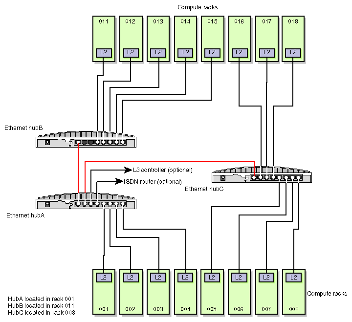
An optional ISDN router can be added to the Ethernet hub network to allow a secure remote connection. The ISDN router is located on the utility shelf in rack 001 and is connected to the Ethernet hub via an Ethernet cable.
