This guide provides basic system setup information, from unpacking to booting your SGI 1450 Server, as follows:
See the SGI 1450 Server Mounting Instructions for a description of how to mount the system into a rack. (Consult the SGI 1450 Server Documentation CD for SGI 1450 Server manuals available in ten languages.)
See the SGI 1450 Server User's Guide for more detailed information, including additional configuration information and the installation of customer-replaceable components.
To obtain SGI documentation using the World Wide Web, go to the SGI Technical Publications Library at http://techpubs.sgi.com. Enter a keyword search, or search by title to find the information or manual you need.
 | Warning: To avoid personal injury when unpacking the server, use only a mechanical assist unit to lift it off the shipping pallet. The minimum server configuration weighs 26 kg (57 lbs); the maximum configuration weighs 40 kg (88 lbs). Do not attempt to lift or move the server by the handles on the power supplies. Use only a hand-truck or other mechanical assist unit to move the server from one location to another. |
Remove the server from the packaging container and check that all accessories are included. Inspect the packaging container for evidence of mishandling during transit. If the packaging container is damaged, photograph it for reference. After removing the contents, keep the damaged container and the packing materials.
Inspect the server and accessories for damage. If the contents appear damaged, file a damage claim with the carrier immediately.
The SGI 1450 Server is designed to be either mounted in a standard 19-inch rack (rack mode) or standing upright (pedestal mode).
For instructions on mounting the SGI 1450 Server, see the SGI 1450 Server Mounting Instructions.
The following table specifies the space requirements for the SGI 1450 Server system.
Table 1-1. SGI 1450 Server Physical Specification
Specification | Rack Mode |
|---|---|
Height | 4u (7 inches) |
Width | 17.5-inch rack |
Depth | 26.5 inches |
Weight | 57 lbs. (26 kg), minimum configuration 88 lbs. (40 kg), maximum configuration |
Required front clearance | 3 inches (inlet air temperature <35 ˚C / 95 ˚F) |
Required rear clearance | 6 inches (no airflow restriction allowed) |
Required side clearance | 1 inch |
The server operates reliably within normal office environments. Select a site that meets these criteria:
Near a properly earthed, grounded, three-pronged power outlet, as follows:
In the United States and Canada: a NEMA 5-15R outlet for 100-120 V and a NEMA 6-15R outlet for 200-240 V.
In other geographic areas: a properly earthed, grounded outlet in accordance with the local electrical authorities and electrical code of the region.
Clean and relatively free of excess dust.
Well ventilated and away from sources of heat, with the ventilating openings on the server kept free of obstructions.
Away from sources of vibration or physical shock.
Isolated from strong electromagnetic fields and line noise caused by electrical devices such as elevators, copy machines, air conditioners, large fans, large electric motors, radio and TV transmitters, and high-frequency security devices.
Access space provided so the server power cords can be unplugged from the power supply or the wall outlet; this is the only way to remove AC power from the server.
Clearance provided for cooling and airflow.

Caution: In regions that are susceptible to electrical storms, it is recommended that you plug your system into a surge suppressor and disconnect telecommunication lines to your modem during electrical storms.
| Warning: Never modify a supplied AC power cord. Do not use a supplied AC power cord if it is not the exact type required in the region where the server will be installed and used. Replace the cord with the correct type. Refer to the cord requirements described below. Do not plug in the server power cord yet if you will be adding internal parts (boards, DIMMs, removable media drives). |
| Caution: The power supply in this product contains no user-serviceable parts. There may be more than one supply in this product. Obtain servicing only from qualified personnel. The DC power on/off button on the system does not turn off system AC power. To remove AC power from the system, you must unplug each AC power cord from the wall outlet or power supply. |
The power cords must meet these requirements:
Rating: Cords must be rated for available AC voltage and have a current rating at least 125% of the current rating of the server.
Connector, wall outlet end: Cords must be terminated in a grounding-type male plug designed for use in your region. It must have certification marks showing certification by an agency acceptable in your region.
Connector, server end: The connector that plugs into the AC receptacle on the server must be an IEC 320, sheet C13, type female connector.
Cord length and flexibility: Cords must be less than 4.5 meters (14.76 feet) long, and must be flexible (harmonized) or VDE-certified to comply with the server's safety certifications.
Connect the monitor, keyboard, mouse, and other external devices to their appropriate ports.
| Caution: Before connecting external devices, make sure the server is not plugged in, or equipment could be damaged. |

Rear panel I/O ports and features are indicated in Figure 1-1, as follows:
A. AC input power connector
B. Optional external SCSI connector ports
C. Hot-plug 64-bit, 33 MHz PCI add-in board slots
D. Hot-plug 64-bit, 66/33 MHz PCI add-in board slots
E. Non-hot-plug 32-bit, 33 MHz PCI add-in board slots
These slots can also accept an optional Intelligent Chassis Management Bus (ICMB) SEMCONN 6-pin connector in/out, port 1
F. Video connector
G. USB ports 0 (upper) and 1 (lower), 4-pin connectors
H. NIC RJ45 connector
I. Serial port 2 (COM1), 9-pin RS-232 connector
J. IEEE 1284 compliant, 25-pin bi-directional parallel connector
K. Serial port 1 (COM1), 9-pin RS-232 connector
L. PS/2-compatible keyboard connector
M. PS/2-compatible mouse connector
N. HW push button
O. PCI green and amber LEDs on the inside of the chassis
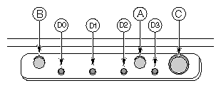
The following front controls and indicators are shown in Figure 1-2.
A. Power on/off button: If you press this button when the system is off, you turn on the power subsystem. If you press this button when the system is in sleep state, you activate it. If you hold down the button for more than 4 seconds, you override the ACPI mode and the power is turned off.
B. Reset button: If you press this button, you reset the system. If you hold down this button for 4 seconds or more the CMOS will be cleared if the power button is pushed, and then both the reset and power buttons are released within one second of each other.
C. Sleep button: If the operating system supports ACPI and you press this button, the operating system goes into sleep state (S1). If you press this button during sleep state, the operating system becomes active. This system does not have a service mode.
D. Front panel LEDs from left to right:
D0. General System Fault LED: Yellow indicates a system failure.
D1. NIC activity LED: Green indicates NIC activity.
D2. HDD activity LED: Green indicates any system hard drive activity.
D3. Main Power LED: Solid green indicates the presence of DC power in the server. Flashing green indicates that the system is in ACPI sleep mode.
Make sure all external devices, such as monitor, keyboard, and mouse, have been connected.
If present, remove the drive protection card from the diskette drive.
Turn on the video monitor.
Plug the female end of the server AC power cord into the input receptacle on the back of the chassis.
Plug the male end of the server AC power cord into a wall outlet. Choose a grounded, three-pronged AC power outlet; see “Choosing a Site” for outlet information.

Note: When you plug the AC power cord into a wall outlet, the server may turn on and boot automatically. In this case, you do not need to press the power on/off power button on the front panel. If the server does not turn on when you plug it into the AC outlet, press the power on/off button on the front panel. (See Figure 1-2.)
Verify that the main power LED on the front panel is lit (see Figure 1-2 ). After a few seconds, the power-on self test (POST) begins.
Each time you turn on the system, the BIOS begins executing the power-on self test (POST). POST discovers, configures, and tests the processors, memory, keyboard, and most installed peripheral devices. The length of time needed to test the memory depends on the amount of memory installed. POST is stored in flash memory.
Turn on your video monitor and system. After a few seconds, POST begins to run and a splash screen is displayed.
While the splash screen is displayed, you can either:
Press F2 to enter the BIOS setup.
OR
Press Esc to change the boot device priority for this boot only. See “Changing the Boot Device Priority Temporarily”.
After pressing F2 or Esc during POST, you can press Ctrl+A to run the SCSISelect utility.
If you do not press F2 or Esc and do NOT have a device with an operating system loaded, the boot process continues and the system beeps once. The following message is displayed:
Operating System not found
At this time, pressing any key causes the system to attempt a reboot. The system searches all removable devices in the order defined by the boot priority.
If you want to boot from a hard drive loaded with an operating system, make sure that the hard drive is installed and push the reset button on the front panel. (see Figure 1-2.)
Note: The SGI 1450 Server is shipped with the diskette drive set as the first boot device. Therefore, the server tries to boot from a diskette rather than from the CD-ROM, of whether or not a CD is in the CD-ROM. If you want to set the CD-ROM as the first boot device for this boot only, press Esc. If you want to permanently set the CD-ROM as the first boot device, press F2 to change the boot device priority in the BIOS setup. After POST completes, the system beeps once. If an operating system is loaded, the operating system takes control of the server system.
During POST, you can change the boot device priority for the current boot process. The changes described below are not retained for the next boot process.
Boot the server. The CD must be in the drive.
At any time during POST, press Esc. When POST completes, a pop-up Boot menu appears.
Use the arrow keys to highlight the device from which you want the server system to boot first. For example, if you want the server system to boot from the CD-ROM first, you select CD-ROM Drive.
Note: One of the selections on the pop-up Boot menu is Enter Setup. Selecting this option brings you into the BIOS setup. Press Enter.
The bootup process continues. When the process is finished, a system prompt is displayed.